1
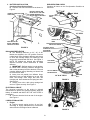
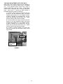
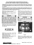
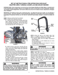
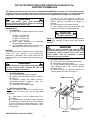
SET-UP INSTRUCTIONS & PRE-OPERATION CHECKLIST for
SNAPPER SCRAMBLERS
The following instructions cover the set-up of SNAPPER SCRAMBLERs. Complete each of the following steps
carefully. Review and complete each item as instructed on the Pre-Operation checklist. The Snapper Product
Registration card must be filled out and sent to Customer Service department at Snapper when completed.
C. With all cell caps removed, connect an
automotive type battery charger to battery terminals;
RED to positive (+) and BLACK to negative (-)
terminal.
D. Slow charge at 1 to 2 amps for 2 hours.
E. After charging, check level of electrolyte, add
electrolyte if necessary, and tighten cell caps.
WARNING
Wear heavy leather gloves when handling or
working around cutting blades. Blades are extremely
sharp and can cause severe injury.
MOWING DECK
1. Cutting Blade
A. Check torque of blade mounting bolts. Torque
to:
33” Deck - 30 to 40 ft. lbs.
38” Deck - 80 to 90 ft. lbs.
42” Deck - 30 to 40 ft. lbs.
48” Deck - 60 to 70 ft. lbs.
B. Check blade straightness per operator’s
manual supplied with machine.
C. After completing blade check, carefully lower
SCRAMBLER to floor to continue set-up.
WARNING
DO NOT OVERFILL!
NOTE: 3/16” above cell plates is the recommended level.
Never place anything in battery other than specified
electrolyte.
WARNING
Shield the positive terminal with terminal cover
located on battery harness. This prevents metal from
touching the positive terminal, which could cause
sparks. Cables must be connected to battery
terminals in the proper position.
BATTERY
Electrolyte required for dry batteries must be purchased
locally. Pay close attention to the precautionary
statements on the battery and in these instructions. All
batteries require a slow charge before being placed into
service.
3. BATTERY INSTALLATION
A. Tilt seat up to gain access to battery cradle.
B. Slide battery into battery cradle.
C. Connect cables to battery terminals. Connect
RED (Positive) cable first. Connect BLACK
(Negative) cable.
D. Place the positive (+) terminal insulator over
positive terminal and cable. See Figure 1.
WARNING
DO NOT attempt to charge battery while installed on
the Zero Turning Radius machine. DO NOT use
“BOOST” chargers on the battery.
1. BATTERY REMOVAL
A. Tilt seat up to gain access to battery.
B. Observe and note cable positions on battery.
See Figure 1.
C. Disconnect cables from battery terminals,
disconnecting BLACK (Negative) cable first.
Retain mounting bolts and nuts.
D. Slide battery from battery cradle.
TERMINAL INSULATOR
POSITIVE
CABLE
NEGATIVE
CABLE
2. BATTERY ACTIVATION
NOTE: The electrolyte (acid) for the battery is not
supplied with the mower and must be purchased
separately.
POSITIVE
TERMINAL
A. Place battery in a well ventilated area on a
level surface.
B. Remove battery cell caps. Fill cells as required
with electrolyte to between minimum and maximum
fill line as viewed from outside battery case. Filling
battery with electrolyte will bring the battery to 80%
charged state.
NEGATIVE
TERMINAL
(Installation Continued
on Next Page)
FIGURE 1
INSTRUCTION No. 5-0410 (I.R. 9/29/03)
1
PRE-OPERATION CHECK
Complete all items on the Pre-Operation Checklist as
instructed.
3. BATTERY INSTALLATION
(Continued from Previous Page)
E. Connect over flow tube and route as shown in
Figure 2.
CONNECT OVER FLOW TUBE
TO BATTERY
BATTERY CABLES ARE
INSTALLED AT THIS TIME
SHOWN REMOVED FOR
BETTER VIEW OF BATTERY
42” DECK
INSTALL NUTS
HERE
33” DECK
INSERT TUBE INTO HOLE
IN SEAT PEDESTAL
INSTALL NUTS
HERE
ONCE INSTALLED
ROUTE TUBE AWAY
FROM TOP OF DECK
DEFLECTOR SPRING
FIGURE 2
DISCHARGE DEFLECTOR
A. The discharge deflector on 33”, 42” & 48”
Models are shipped in the “UP” position. Remove
rubber band, lower discharge deflector and secure
to deck with carriage bolt(s), flat washer(s) and
wing nut(s) furnished with the deck. See Figure 3.
NOTE: 38” Models are shipped with discharge
deflector removed. Follow instructions to install
deflector.
1. IMPORTANT: Deflector spring is under tension,
be careful when removing. Remove carriage bolt
and nut that secures pivot rod to the deck. Pivot rod
contains deflector spring. Mounting rod should not
be removed from deck.
2. Insert pivot rod partially into deflector hinge,
slide spring onto rod with straight leg on top, then
insert rod through other hinge and then into
mounting rod. Insert hooked end of spring into deck.
See Figure 3.
3. Secure pivot rod to deck using carriage bolt
and nut. Tighten securely. See Figure 3.
STRAIGHT LEG OF
SPRING ON TOP OF
DISCHARGE
DEFLECTOR
PIVOT
ROD
LOCKNUT
DISCHARGE
DEFLECTOR
SPRING
SLOT IN
DO NOT REMOVE
MOUNTING ROD
38” & 48” DECK
FIGURE 3
ELECTRICAL CIRCUIT
The electrical connection at the engine is shipped
disconnected to protect the electrical system when the
battery is installed and MUST BE THE LAST STEP in
preparation.
A. Connect electrical circuit at rear of the engine.
See Figure 4.
LUBRICATION and FUEL
1. Engine
A. Perform normal engine service, oil and fuel,
according to engine manufacturer’s recommendations found in the Engine Owner’s Manual.
FIGURE 4
2
CARRIAGE
BOLT
TRACKING ADJUSTMENTS (SZT UNITS ONLY)
When both motion control levers are fully engaged in
forward drive, the machine should move in a straight
line. If the machine tracks (veers) left or right, a
tracking adjustment must be made. Each motion
control lever is equipped with a tracking adjustment
plate. See Figure 5. Moving the plate forward or
backward adjusts the machine’s tracking:
1. If mower tracks to the left, loosen the two torx
screws on the left adjustment plate, slide plate
forward approximately 1/8”, and retighten screws.
(If plate is already as far forward as it can go,
loosen the right plate and slide back 1/8”.) Check
machine tracking and repeat as needed.
2. If mower tracks to the right, loosen the two torx
screws on the right adjustment plate, slide plate
forward approximately 1/8”, and retighten screws.
(If plate is already as far forward as it can go,
loosen the left plate and slide back 1/8”.) Check
machine tracking and repeat as needed.
3. In cases of severe tracking, one plate may
need to be moved fully back and the other moved
fully forward.
ADJUST
TRACKING
ADJUSTMENT
PLATE
FIGURE 5
3
PRE-OPERATION CHECKLIST
Snapper has completed initial adjustments and performed operational tests prior to shipping the machine. Due
to the possible effects of shipping, handling and storage, Snapper intends for all of the following items to be
verified and necessary final adjustments made at time of setup. It remains good practice and is strongly
recommended that all the items also be checked prior to placing the machine into service. It is very important
that setup is verified and all operational tests completed and results are acceptable. After completing this form,
sign and retain for future reference.
CUTTING BLADE & MOWER
__ BLADE RETAINING hardware checked for proper tightness. Check alignment.
__ BLADE TIP CLEARANCE inside lower edge of mower checked and corrected as needed.
__ MOWER CUTTING HEIGHT settings checked and adjusted as needed (with tires properly inflated).
__ MOWER SIDE TO SIDE level checked and adjusted as needed (with tires properly inflated).
__ MOWER FRONT TO REAR setting checked and adjusted as needed (with tires properly inflated).
__ DISCHARGE DEFLECTOR positioned, secured and tightened into place.
PRE-START CHECKS & SERVICES
__ TIRES checked and inflated to correct pressures. Both Front and Rear are 12 psi.
__ ENGINE OIL level checked. Refer to Engine Owner’s Manual for proper oil specifications
__ FUEL added to tank and system checked for leaks. Refer to Engine Owner’s Manual for fuel specifications.
__ BATTERY (Not overfilled!) activated and charged per battery instructions
__ BATTERY reinstalled and properly connected with red boot over positive terminal.
__ LUBRICATION of entire unit completed.
OPERATIONAL TESTS
__ CHECK SEAT SWITCH for proper function
__ INTERLOCK SYSTEMS checked to insure proper functioning.
__ ENGINE STARTED and throttle control settings checked.
__ ALL OPERATIONS as listed on console checked.
__ IGNITION SWITCH checked to insure engine stops when turned to OFF position.
__ PARKING BRAKE tested to insure proper operation.
__ PARKING BRAKE SWITCH checked to insure proper operation and function.
__ BLADE ENGAGEMENT SWITCH tested for operation and function for engagement and disengagement of blade.
__ BLADE BRAKE function verified. Blade rotation stops in 5 seconds or less.
__ TRACKING adjustments made to insure mower drives in a straight line.
CONSUMER INFORMATION
SALE DATE
MODEL
Retailer's Name
SERIAL NO.
Signature
Address _____________________________ City
MACHINE WILL BE USED COMMERCIALLY? YES ______________
State
Zip
State
Zip
NO
Signature
Purchaser's Name
Address _____________________________ City
IMPORTANT: This form is to be retained for future reference regarding Warranty, proof of purchase, traceability
for product recall or service, etc. Complete the SNAPPER Product Registration Card immediately and mail to:
Customer Service Department at SNAPPER, P.O. BOX 1379, McDonough, Georgia, 30253.
INSTRUCTION No. 5-0410 (I.R. 9/29/03)
4