1
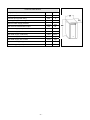
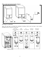
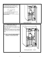
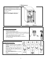
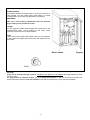
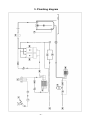
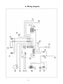
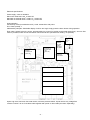
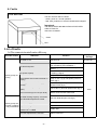
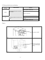
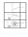
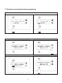
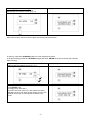
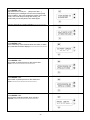
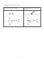
INSTALLATION,
USER AND MAINTENANCE MANUAL
FOR WATER OSMOSIS UNIT
WO-01
EQUIPMENT FOR POTABLE WATER TREATMENT
CONTENTS:
Paragraph
GENERAL WARNINGS.................................................................................................................
TECHNICAL CHARACTERISTICS ...............................................................................................
POSITIONING AND INSTALLATION ............................................................................................
MAINTENANCE ............................................................................................................................
PLUMBING DIAGRAM ..................................................................................................................
WIRING DIAGRAM .......................................................................................................................
FAULTS ........................................................................................................................................
ELECTRONIC CIRCUIT BOARD AND PROGRAMMING .............................................................
EXPLODED VIEWS ......................................................................................................................
LIST...............................................................................................................................................
TECHNICAL INSTRUCTIONS:
These are intended for the qualified staff who are to install, commission and test the appliance
and carry out any servicing and repairs.
USER INSTRUCTIONS:
These provide recommendations for use, a description of the controls and the correct
procedures for cleaning and maintaining the Osmosis Treatment Unit.
WARNINGS:
Warnings regarding operations which are prohibited inasmuch as they can result in injury or
damage.
THIS MANUAL IS AN INTEGRAL PART OF THE OSMOSIS TREATMENT UNIT; KEEP IT
CAREFULLY IN THE VICINITY OF THE MACHINE AND READ THE INSTALLATION AND USER
INSTRUCTIONS CONTAINED IN IT.
- 29 -
1. General warnings
STORAGE:
THE PACKED APPLIANCE MUST BE STORED IN A DRY, CONDENSATION-FREE AREA,
UNDER COVER. THE ADMITTED STORAGE TEMPERATURE IS 4-50°C.
ALWAYS DISCONNECT ELECTRICAL POWER BEFORE WORKING ON THE APPLIANCE OR
DISASSEMBLING IT.
POSITIONING, HOOKUP, COMMISSIONING, TROUBLESHOOTING AND REPLACING POWER
CABLES MUST ALWAYS BE DONE BY QUALIFIED PERSONS.
CHANGES IN THE POWER VOLTAGE OF MORE THAN 10% OF THE RATED VALUE CAN
DAMAGE THE ELECTRICAL CIRCUITS; MONITOR THE MAINS VOLTAGE CONSTANTLY.
THE APPLIANCE MUST BE GROUNDED AS REQUIRED BY ELECTRICAL EQUIPMENT
SAFETY STANDARDS.
THIS UNIT IS INTENDED ONLY FOR THE INTENDED PURPOSE OF TREATING WATER FOR
TECHNICAL PURPOSES.
SHIPPING/DELIVERY:
THERE ARE NO SPECIAL PRECAUTIONS FOR UNPACKING THE APPLIANCE, EXCEPT FOR
THE NORMAL CARE REQUIRED IN HANDLING FRAGILE MATERIALS. BEFORE DISPOSING
OF THE PACKAGING, MAKE SURE IT DOES NOT CONTAIN ANY PARTS, INSTRUCTION
BOOKLET OR OTHER DOCUMENTATION.
THE PACKAGING (CARDBOARD, EXPANDED POLYSTYRENE, PALLET, ETC.) MUST NOT BE
LEFT WITHIN THE REACH OF CHILDREN, SINCE THEY ARE HAZARDOUS MATERIALS.
THE OSMOSIS TREATMENT UNIT MAY BE REMOVED FROM ITS ORIGINAL POSITION ONLY
BY SPECIALISED PERSONS.
WHEN CLEANING THE APPLIANCE DO NOT USE CORROSIVE PRODUCTS, ACIDS, STEEL
PADS OR BRUSHES.
DO NOT WASH THE APPLIANCE WITH DIRECT OR HIGH PRESSURE JETS OF WATER.
THE MANUFACTURER DECLINES ALL LIABILITY FOR INJURY/DAMAGE TO PERSONS OR
PROPERTY CAUSED BY NON-OBSERVANCE OF THE INSTRUCTIONS GIVEN IN THIS
MANUAL, INCORRECT USE, TAMPERING BY UNQUALIFIED PERSONS, TAMPERING WITH
EVEN ONE PART OF THE APPLIANCE, OR THE USE OF NON-ORIGINAL SPARE PARTS, OR
MODIFICATIONS, ACCESSORIES OR DEVICES OF ANY KIND APPLIED TO THE APPLIANCE
UNLESS EXPRESSLY SPECIFIED IN THIS MANUAL.
- 30 -
THIS APPLIANCE IS MARKED AS REQUIRED BY EU DIRECTIVE 2002/96/EC, WASTE
ELECTRICAL AND ELECTRONIC EQUIPMENT (WEE).
BY MAKING SURE THAT THIS PRODUCT IS DISPOSED OF CORRECTLY THE USER
HELPS TO PREVENT POTENTIAL DETRIMENTAL EFFECTS ON HEALTH AND THE
ENVIRONMENT.
THE SYMBOL
ON THE PRODUCT OR IN THE TECHNICAL DOCUMENTATION
INDICATES THAT THIS PRODUCT MUST NOT BE TREATED AS ORDINARY DOMESTIC
WASTE BUT MUST BE CONSIGNED TO THE SPECIAL COLLECTION POINT FOR THE
RECYCLING OF ELECTRICAL AND ELECTRONIC EQUIPMENT.
WHEN DECOMMISSIONING THE APPLIANCE COMPLY WITH THE LOCAL WASTE DISPOSAL
REGULATIONS.
FOR FURTHER INFORMATION ON THE TREATMENT, RECOVERY AND RECYCLING OF THIS
PRODUCT, CONTACT THE COMPETENT LOCAL OFFICE, THE DOMESTIC WASTE
COLLECTION SERVICE, OR THE SHOP WHERE THE PRODUCT WAS PURCHASED.
FOR ANY TECHNICAL OR OPERATIONAL INFORMATON, PLEASE CONTACT OUR
TECHNICAL SERVICE DEPARTMENT.
IMPORTANT:
DURING THE WARRANTY PERIOD THE MACHINE MAY NOT BE WORKED ON WITHOUT
ADVANCE AUTHORISATION FROM OUR TECHNBICAL SERVICE DEPARTMENT. FAILURE
TO ABIDE BY THIS RULE VOIDS THE WARRANTY.
2. Technical characteristics
GENERAL DESCRIPTION:
THE APPLIANCE PRODUCES OSMOSIS- TREATED WATER, WITHOUT DISSOLVED SALTS,
WITH A RESIDUAL CONDUCTIVITY IN THE RANGE 20 TO 100 MICROSIEMENS, INTENDED
EXCLUSIVELY FOR TECHNOLOGICAL APPLICATIONS. THE UNIT CONSISTS OF AN ARRAY
OF FILTER CARTRIDGES. THE INVERSE OSMOSIS MEMBRANES ARE LODGED IN
POLYPROPYLENE HOUSINGS. THE OSMOSIS PUMP IS CONSTRUCTED IN BRASS
Dimensions
Height
814
mm
Empty weight
60
kg
Width
376
mm
Empty weight including packaging
67
kg
Depth
600
mm
Installation characteristics
Power cable
3x1 length 1.5 m
Plug
Schuko
Length of filler pipe
1.5
m
Filler pipe collar
¾
inches
Diameter of waste discharge pipe
4
mm
Length of waste discharge pipe
1.5
m
Delivery fitting
3/4
inches
- 31 -
Technical characteristics
Single phase power voltage
230
v
Frequency
50
Hz
Osmosis pump power rating
450
w
Delivery pump power rating
300
w
150-600
(1.5-6)
kPa
(bar)
Max osmosis-treated water output
150
l/h
Max water supply temperature
30
°C
Max water supply hardness
40
°F
Max water supply conductivity
2.000
µS/cm
Max water supply chlorine content
<0.1
mg/l
Max water supply iron content
<0.02
mg/l
Min/max delivery pump pressure
0.5-1.8
Bar
20
l/h
Min/max water supply pressure
Max delivery pump output
- 32 -
3. Positioning and installation
THE APPLIANCE MUST BE CONSIDERED AND HANDLED AS FRAGILE MATERIAL.
THE CIRCUIT DOWNSTREAM OF THE UNIT MUST BE CONSTRUCTED IN PLASTIC AND
STAINLESS STEEL TO PREVENT CORROSION.
IF THE WATER SUPPLY CONTAINS PARTICLES IN SUSPENSION, AN EXTERNAL FILTER
MUST BE INSTALLED TO PROVIDE SUFFICIENT DOWNSTREAM FLOW AND PRESSURE ;
THIS FILTER MUST BE KEPT IN PERFECT CONDITION AT ALL TIMES .
Positioning:
Before installing the appliance, check that there is sufficient clearance for easy extraction of consumables and
for servicing the unit. Check that there is a power socket in the vicinity of the unit. The appliance is designed for
installation in clean area, protected from freezing temperatures.
Before installation, check:
- that there is sufficient space for the plumbing
- that there is good access for equipment, inspections and maintenance
Electrical hookup:
Make sure the power supply is adequate to the unit’s draw.
Caution: the power voltage rating is given on the unit’s dataplate.
WARNING: Do not open the unit’s electrical panel ; only qualified persons may do this.
Plumbing hookup:
Hook the machine up as indicated on the unit itself, “IN” indicates the water supply inlet, “OUT” indicates the
osmosi-treated water outlet, RJ indicates the discharge outlet. Remove the red cap “T” from the RJ fitting and
insert the water drain pipe supplied with the unit.
Apply the supplied pipe to the OUT fitting and equip its free end with a corrosion-proof cock if it is not hooked up
directly to the service.
The water supply pressure may not exceed 6 bar nor be less than 1.5 bar.
WHEN FIRST RUNNING THE UNIT AND AFTER ANY SERVICE, RUN THE WATER DELIVERY
TO A DRAIN FOR AT LEAST 20 MINUTES SO AS TO ELIMINATE ANY IMPURITIES
RESULTING FROM THE WORK JUST DONE
All quick fittings are of the type
- 33 -
Water circuit and electrical hookup diagram
Installing the membranes
Open the front door to access the membrane housings, which must be kept in their original
packaging until the machine is started up
Disconnect
the quick coupling
hoses
Undo
the base
Membrane mount
- 34 -
Fit
the membrane
Screw on
the base
Reconnect
the hoses
Pressurizing and starting up the unit:
After all pipes have been connected, pressurise
the system gradually and check for leaks.
Turn the “Osmosis pump” switch to “I”. Check
that the following message displays:
In normal operation the value Rj varies during
osmosis-treated water production.
Wait 5-10 minutes, then continue by starting up
the delivery pump.
Osmosis pump switch
I M P O R T A N T !!!
Delivery pump startup (first startup)
Remove the red bleeder cap P (“Sfiato innesco”)
on the front (close to the pressure gauge,
labelled as such) .
To remove the cap, press the John Guest clip
and allow a bit of water to run into a container;
refit the cap P, and actuate the “Delivery pump”
switch.
FAILURE TO FOLLOW THIS PROCEDURE TO
THE LETTER CAN CAUSE SERIOUS
DAMAGE TO THE DELIVERY PUMP.
Delivery pump switch
- 35 -
Cap “P”
4. Maintenance
The osmosis treatment unit runs completely
automatically and maintenance is minimal. The
only essential operation is periodic replacement
of the filter cartridges.
IMPORTANT
Replace the pre-filter every 3000 hours of
operation and AT LEAST 1 time a year.
Pre-filter
Replacing the pre-filter:
Filter cartridge replacement procedure
- Shut off power;
- Close the side cocks (RL);
- Vent the circuit from the top cap (S);
- Unscrew the filter housing (use the special wrench supplied in the
accessories bag). Place a container to drain the water in the filter
into;
- Fit the new cartridge and check it is correctly seated;
- Close vent S and open the side cocks RL;
- Check for leaks and water in the bottom of the appliance;
- Dry it off thoroughly.
Replacing the membranes:
Cartridge replacement procedure.
- Shut off power;
- Disconnect all hoses from the membrane
housings, unscrew the base, and place a
container to catch the water contained in the
cartridges;
- Refit the membrane, check the seating of the
o-ring and screw the housing fully in;
reconnect the hoses and make sure they are
correctly seated;
- Do not apply excessive force;
- Fit the new cartridge and check it is correctly
seated;
- Start the unit up and check for leaks.
- 36 -
Membrane
Special adjustments:
RECIRCULATION
Recirculation retreats the waste water to reduce the amount of
water rejected. Turn the needle valve “Recirculation” to retreat
the waste water, thus reducing overall water consumption.
Important!
Make sure, when making adjustments, that the pressure
gauge reading never exceeds 10-11 bar.
BYPASS
Turn the “Bypass” needle valve to adjust the conductivity of the
osmosis-treated water, at the expense of the hourly water
production and the amount of water rejected.
NOTE:
In both cases, before setting the needle valves you must slacken
off their collars and tighten them down after the adjustment has
been made.
Recirculation
Bypass
Collar
Inactivity:
There are no special warnings regarding maintaining the appliance’s operability when kept inactive for short
periods of time.
For long periods of inactivity contact your local Authorised Reseller so that he can remove and store the
inverse osmosis membranes and also restart the unit after recommissioning as for the first installation.
- 37 -
5. Plumbing diagram
- 38 -
LEGEND HYDRAULIC DIAGRAM
IN
E1
P1
FIL
M1
SR
VR
MP
SM
MO
CO
Water inlet
Filler solenoid valve
Filler pressure switch
Filter - CARBONLOK 5 micron
Osmosis pump
“Re-treatment” needle valve
Non-return valve
Pump pressure gauge
Mixer needle valve
Osmosis membrane
Conductivity meter
F1
P2
R
M2
F2
E2
SS
VE
P3
SC
PR
Product flow meter
Delivery minimum pressure switch
Vat cock
Delivery pump
Waste flow meter
Discharge solenoid valve
Discharge choke
Espansion tank
Delivery pressure switch
Water discarded
Produced water
LEGEND ELECTRIC DIAGRAM
SA
CO
LR
LV
SE
M2
P3
P2
SS
IR
Anti flooding sensor
Conductivity meter
Red led
Green led
Electronic board
Delivery pump
Delivery pressure switch
Delivery minimum pressure switch
Shuko plug
Delivery switch
IO
E1
E2
M1
LB
LA
PB
F2
SE
F1
- 39 -
Osmosis switch
Filler solenoid valve
Discharge solenoid valve
Osmosis pump
Low level switch
High level switch
Low pressure switch
Waste flow meter
Selector
Product flow meter
6. Wiring diagram
- 40 -
Electrical specifications:
Power supply: 230v AC 50/60Hz
Max motor outlet load: 16A_ at 230V AC
Max load on solenoid valve 1 outlet: 1A_ at 230v AC
Max load on solenoid valve 2 outlet: 1A_ at 230V AC
Instrumentation:
Conductivity meter (normalised at 20°C ) scale: 0-200uS/cm with probe
K=5. Class (overall): 1
Calibrated by samples. Switchable display of uS/cm and mg/l; simply press the down button during operation.
Flow meter: pulses/l given by sensor: programmable (to account for laminar and lamellar water flow). Just one flow
meter is provided, which can be switched to read a second flow (simultaneous reading: not possible).
HOOK UP J4
RED ALARM
LED
(RES 390)
+
-
HOOK UP J2
GREEN
POWER LED
(RES 390)
+
-
MAX
PRESS.
ALARM
TRIPS
WHEN IT
CLOSES
CONDUCTI
VITY
METER
CELL
INPUT, FLOODING
AND MAX
PRESSURE
Minimum pressure switch
High level
Low level
Flow meter switch
Flow meter
Inputs: high level, low level, flow meter switch, minimum pressure switch: inputs receive only voltage-free
contacts. Caution: do not route these cable together with power or other loads (duct them separately).
- 41 -
6- Faults
Front door leds
The door has two leds to indicate:
- Green: power on, normal operation;
- Red: fault, production of osmosis-treated water stopped
Important:
THE DOOR GIVES NO INDICATION OF DELIVERY
CIRCUIT FAULTS
See below for details.
Green
Red
List of faults
A) No osmosis-treated water delivery
Possible causes
Subcause
Solution
No water in vat
See point "B"
see point "B"
Check power supply and power switch ON
(see “Positioning and installation”)
Power plug not inserted in electrical panel
(insert)
Check connections and whether board
is sending a signal
Pump condenser faulty (replace)
No electrical power
No power to pump
Delivery pump not
running
Display alarm
message
Vat pressure switch faulty (jammed on
empty)
Empty vat (manually with jumper on delivery
pump or cock –fig.4) and replace pressure
switch (fig.1)
Delivery pressure switch faulty (jammed Replace, or adjust the pressure with the
on full)
adjuster screw (fig.2)
Non-return valve jammed (does not
open)
Check valve, if jammed replace/clean (fig.3)
Vat not full enough for use (min level)
Wait for a few minutes while it fills
No water arriving at pump: vat suction
pipe blocked/crimped/cock closed
Remove obstacle/open cock (fig.4)
Air in delivery pipe
Delivery pump runs
but does not deliver Impeller damaged/broken
or only insufficiently
The user requires minimum intake
pressure of >1.8 BAR
The user requires flow > 20 l/min
- 42 -
Shake pipe and see if air rises into the vat
Replace
System limit
Reduce user load
none
B) Osmosis-treated water not produced
Possible
causes
Subcause
Solution
Check power supply and power switch ON
(see “Positioning and installation”)
No electrical power
No power to pump
Intake pressure switch faulty (jammed on full)
Power plug not inserted in electrical panel
(insert)
Check connections and whether board is
sending a signal
Pump condenser faulty (replace)
Replace, or adjust the pressure with the
adjuster screw (fig.5)
Vat level switch (low) faulty (jammed on full)
Max level switch faulty, does not send
production enable signal (replace/clean)
(see wiring diagram)
No water supply or supply pressure/flow
inadequate
- Supply cock closed OPEN;
- Supply filter blocked CLEAN
- Supply pressure should be > 1.5 bar
- Pre-filter up/downstream cocks closed
OPEN (see maintenance section)
- Filter blocked – REPLACE (fig.5)
- Filler solenoid valve faulty or no power –
REPLACE IF FAULTY (fig.5)
- Intake pressure switch faulty (jammed on
empty) – REPLACE (fig.5)
Osmosis pump
not running
Water in vat
Osmosis pump
running but
production low
Display
alarm
message
Vat level switch (high) faulty, does not
switch to full: continues producing with
overflow. REPLACE (see wiring diagram)
Water supply too cold (<10°)
Increase supply temperature
Pre-filter blocked
Replace pre-filter (see maintenance
section)
Membranes blocked
Replace membranes (see maintenance
section)
Impeller damaged/broken
Check pressure gauge reading
if > 8, replace pump or impeller as
required
Bypass valves need adjustment
See special adjustments section
Discharge pipe crimped
Route pipe properly
Pressure drop in vat supply hoses
Shut off power, dry thoroughly and repair
leak
- 43 -
none
Low pressure
Flooding
alarm
C) Water production not conforming
Display alarm
message
Cause of alarm
Solution
Adjust "bypass" needle valve
The treated water does not conform
with settings
HHHH
Replace membranes
Replace pre-filter (see maintenance section)
LLLL
The water production is below the set
value
Replace membranes (see maintenance
section)
Adjust "bypass" needle valve
Figures
Pressure switch
Fig.1
Delivery pressure
switch with adjust
screw
Fig.2
- 44 -
Non-return valve
Fig.3
Vat cock
Fig.4
Pressure switch
Solenoid valve
Filter
Fig.5
- 45 -
7. Electronic circuit board and programming
Hold down F1 and press ENTER to enter conductivity programming.
We can now read the calibrated value.
Press UP/DOWN to set the value.
Press ENTER to save and quit.
Press F1 to abort without saving.
- 46 -
Display:
In standby (system not running) :
Pressing F1 runs a water flushing cycle.
X.X indicates the software version (e.g. 2.1)
After a few minutes, switch off and on again with the osmosis pump switch.
In stand by: hold down UP/DOWN together to enter programming mode:
(in all the following procedures: UP/DOWN changes the value, ENTER saves and continues, F1 continues
without saving).
Programming procedures: >>>>>>>>>>>>>>>>>>>>>>>>
X.X indicates the software version (e.g. 2.1)
Press ENTER or F1:
Flussaggio auto (auto flush):
This is an auto flush cycle run by the system to prevent
stagnation in the circuit. After the set number of hours, the
solenoid valves open to flush/refresh the water in the
circuit.
- 47 -
Display: Program filtration hours
Press ENTER or F1:
Stop motore se in moto per … (Stop motor after …)
The following two messages concern the osmosis pump
motor condition. Set = 0 to exclude this mode; if the value
is not 0, the motor stops running after having run
continuously for the set period, then starts again.
After two seconds, the system displays:>>>>>>>>>>>>>>
Press ENTER or F1:
If the conductivity value remains below set value, no alarm
trips, otherwise an alarm displays.>>>>>>>>>>>>>>>>>>>
Press ENTER or F1:
Set number of pulses per litre for the product flow
meter.>>>>>>>>>>>>>>>>>>>>>>>>>>
Press ENTER or F1:
Set number of pulses per litre for the waste flow
meter.>>>>>>>>>>>>>>>>>>>>>>>>>>>>
Press ENTER or F1:
Set minimum production below which a fault is
reported.>>>>>>>>>>>>>>>>>>>>>>>>>>>>
- 48 -
Press ENTER or F1; the system returns to standby.
The switch at the top of the display, if pressed to the right,
switches from the waste water flow display
- 49 -
to the osmosis-treated water flow display. When it
is released, the display returns to waste water
flow mode.