1
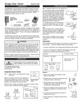
INSTALLATION
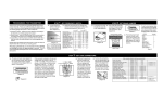
PROGRAMMING THE RECEIVER
The Universal receiver works with Skylink remote transmitters
model #66, #66C, #36, #36C, #68, #68C, #68B, #68G, #68R,
#88, #88C, #88P. Use a paper clip to set the receiver DIP
switches to match your Skylink transmitter. Each switch of the
receiver has 2 positions (“ON” or “OFF”).
DIP
SWITCHES
WARNING: Unplug the
receiver before changing code setting.
Refer to the chart below. If any of the DIP switches in the Universal Receiver
are set to “ON” position, set the switches in the Skylink transmitter to the “+”
position. If DIP switches on the Universal Receiver are set to “OFF” position,
set the switches in the Skylink transmitter to the “0” or central or blank position.
1. Disconnect the power from
your existing garage door
opener to avoid triggering
the door accidentally during installation.
DIP switch setting to match with Skylink Universal Receiver and Skylink Transmitter
UNIVERSAL RECEIVER #UR100
DIP SWITCH POSITION SETTING
1
ON / OFF
2
ON / OFF
3
ON / OFF
4
ON / OFF
5
ON / OFF
6
ON / OFF
7
ON / OFF
8
ON / OFF
9
ON / OFF
2. Open your existing wall
mounted garage door
opener button.
SKYLINK TRANSMITTER
DIP SWITCH POSITION SETTING
1
+ OR 0
2
+ OR 0
3
+ OR 0
4
+ OR 0
5
+ OR 0
6
+ OR 0
7
+ OR 0
8
+ OR 0
9
+ OR 0
from the garage door
opener is connected to.
proper operation.
Existing wall
mounted button
DO NOT REMOVE ANY
WIRES.
Replace button casing.
4. Plug in the wires to the
receiver as shown. Then,
plug in the receiver to an
electrical outlet.
ANTENNA
RECEIVER
3. Connect the wires to the
terminals and tighten as
5. Re-connect the power to
shown. If your opener has
your garage door operator.
more than two terminals,
attach the wire to the same 6. Press the wall button to
test and check wiring for
two terminals that the wire
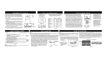
PROGRAMMING THE SKYLINK MODEL #36, 36C
PROGRAMMING THE SKYLINK MODEL #66, 66C
1. Locate frequency switch 2. To program the model 3. Use a pen or paper clip
the transmitter at “0” or
on the top of the trans#66, #66C, open the
to set the corresponding
the center position. (See
mitter and set to position
case with a coin. (See
DIP switches numbered
diagram C)
A. (See diagram A)
diagram B)
1 through 9 so that the
DIP Switch Location
switches on the transmitter match those on
the receiver. Each switch
of the transmitter has 3
positions (“ + ”, “ 0 ”,
“ - ”). To operate with
Skylink #UR-100, only
set the switches to “ + ”
Diagram C
Diagram B
or “ 0 ”. Do not use “ - ”
Diagram A
position. Leave the re- 4. Test the transmitter with
the Universal receiver.
maining DIP switches in
1. Locate frequency switch
on the top of the transmitter to position A.
(See diagram D)
2. To program the model
#36, #36C, open the
case with a coin. (See
diagram E)
Diagram E
Diagram D
3. Use a pen or paper clip
to set the corresponding
DIP switches numbered
1 through 9 so that the
switches on the transmitter match those on
the receiver. Each switch
of the transmitter has 3
positions (“ + ”, “ 0 ”,
“ - ”). To operate with
Skylink #UR-100, only
set the switches to “ + ”
or “ 0 ”. Do not use “ - ”
position. Leave the remaining DIP switches in
the transmitter at “0” or
the center position. (See
diagram F)
DIP Switch Location
Diagram F
4. Test the transmitter with
the Universal receiver.
PROGRAMMING THE SKYLINK MODEL #38, #38C
1. Locate frequency switch
on the top of the transmitter and set to position
A. (See diagram G)
2. To program the model
#38, #38C, open the
case with a coin. (See
diagram H)
3. The transmitter contains 8
brand jumpers (see diagram I) and 12 code connectors. (See diagram J).
Code connector Location
row contains one connector (see diagram K) for a
total of 12 connectors.
Diagram I
4. The brand jumper has 8 rows
of posts, each row has 2 posts.
(see diagram I). The connector, (see diagram K), must be
placed to the position ‘ 7 ’.
Diagram H
Diagram G
1 2 3 4 5 6 7 8
Brand Jumper
5. The code connector (see diagram J) has 12 rows of posts,
each rows has 3 posts. Each
Diagram J
Diagram K
If the connector is placed on the top and middle posts, that
row is set on “ + ” or “ON”. If the connector is removed completely, (not placed on any posts), it is set to “ 0 ” or the neutral position. (see diagram L for examples of how to set a row
to the three different positions).
To operate with Skylink #UR100,
‘+’ OR ‘ON’ ‘0’ = BLANK
only set to “ + ”or “ 0 ” position.
Do not place the connector to
the middle & bottom posts “ - ”
position.
When removing a connector to
set a row to the neutral position,
save the connector in case you
change the code at a later date.
Diagram L
PROGRAMMING THE SKYLINK MODEL #38, #38C
6. To move the connectors, slide an
opened paper clip into the side of
a connector and lift. (see diagram
M) When repositioning connectors, place a connector on the two
chosen posts, then push down on
the connector with your finger.
Paper
Clip
PROGRAMMING THE SKYLINK MODEL #68, #68C, #68B, #68G, #68R
7. Set the connectors numbered 1 through 9 so that
the switches on the transmitter match those on the
receiver. Leave the remaining posts at “ 0 ”,or
the blank position (remove
the connectors). See the
diagram J for details.
1. Locate frequency switch
on the top of the transmitter and set to position
A. (See diagram N)
2. To program the model
#68, #68C, #68B, #68G,
#68R, open the case
with a coin. (See diagram O)
3. The transmitter has 12 rows
of posts, each row has 3
posts. (see diagram P)
4. Use an opened paper clip to set the connectors numbered
1 through 9 so that the switches on the transmitter match
those on the receiver. To operate with Skylink #UR100, only
set to “ + ” or “ 0 ” position. Do not place the connector to
the middle & bottom posts “ - ” position. Leave the remaining
posts at “ 0 ”, or the blank position (remove the connectors).
See the Diagram J for details.
5. Test the transmitter with the Universal receiver.
8. Test the transmitter with
the Universal receiver.
Diagram O
Diagram N
Diagram M
Diagram P
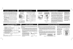
PROGRAMMING THE SKYLINK MODEL #88p
PROGRAMMING THE SKYLINK MODEL #88, #88C
CLOSE
OPEN
2. Set brand jumper by moving the red plastic
tab to the number 7 jumper. Slide an opened
paper clip into the
Frequency
Switch
top of the red plastic
tab, then lift and reposition.
3. Set the frequency
switch located above
to “ D ” position (slide
the switch as far
right as possible).
(See diagram R)
DIP Switch Location
Diagram Q
1 2
3
4
5
6
7
8
Brand Jumper
Diagram R
PROGRAMMING THE SKYLINK MODEL #88p
4. The connector (See diagram V) has 12 rows of posts, each row
has 3 posts. Each row contains one connector (See diagram
W). Set the code connectors from number 1 through 9 so that
the switches on the transmitter match those on the receiver.
To operate with #UR100, only set the connectors to “ + ” or “0”
(blank position). Do not set the connectors to “ - ” position. Leave
the remaining posts at “ 0 ”, or the blank position (remove the
connectors). See the diagram L for details.
4. Use a pen or paper clip
to set the corresponding
DIP switches numbered
1 through 9 so that the
switches on the transmitter match those on
the receiver. Each switch
of the transmitter has 3
positions (“ + ”, “ 0 ”,
“ - ”). To operate with
Skylink #UR-100, only
set the switches to “ + ”
or “ 0 ”. Do not use “ - ”
position. Leave the remaining DIP switches in
WARNING
DO NOT let children
use any garage door
transmitter without
adult supervision.
Children can injure
themselves or others
by the garage door.
1. To Program Your Keypad 2. Set brand jumper by moving the red plastic
- Open the cover on the
tab to the number 7 jumper. Slide an opened
Frequency
back. (See diagram T)
paper clip into the
Switch
top of the red plastic
tab, then lift and reCLOSE
position.
DIP Switch
Location
OPEN
Diagram S
5. Refer to the keypad manual
to test the transmitter with
the Universal receiver.
WARRANTY
If, within one year from date
of purchase, this product
should become defective
(except battery), due to
faulty workmanship or
materials, it will be repaired
or replaced, without charge.
Proof of purchase is
required.
5. Refer to the keypad manual to test the transmitter with the Universal
receiver.
Code connector Location
1 2
The Universal Garage Door
Remote Control is approved
by the FCC and it complies
with Part 15 of the FCC
Rules. Its operation is
subject to the following two
conditions :
1. This device may not
cause harmful interference.
2. This device must accept
any interference that
may cause undesired
operation.
3
4
5
6
7 8
Brand Jumper
Diagram U
Skylink will not be held liable
®
or responsible for
WARNING:
any misuse or application
GARAGE DOOR/
Changes or modifications of this product other than
GATE OPENER
to this unit not expressly
for its intended use.
UNIVERSAL RECEIVER
approved by the party resSKYLINK
USER'S INSTRUCTIONS
ponsible of compliance
TECHNOLOGIES INC.
(Model UR-100)
could void the user’s
2213 Dunwin Drive,
authority to operate the
Mississauga, Ontario
L5L 1X1, CANADA
equipment.
FCC
Diagram V
Diagram W
Diagram T
3. Set the frequency
switch located above
to “ D ” position
(slide the switch
as far right as
possible). (See
diagram U)
(905)608-9223
(905)608-8744 FAX
Email:[email protected]
(Reply within 24 hrs)
Customer Service : (800)304-1187
http://www.skylinkhome.com
P/N. 101A111-003 Rev.3
Patent no. 382251
Patents Pending
©1999 SKYLINK TECHNOLOGIES INC.
® are registered trademarks of their respective corporations
1. To Program Your Keypad
- Open the cover on the
back. (See diagram Q)
the transmitter at “0” or
the center position. (See
diagram S)