1
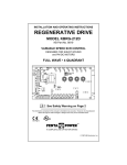
INSTALLATION AND OPERATION MANUAL
KBMG MULTI-SPEED BOARD
KB Part No. 8833 — Multi-Speed Board for KBMG Series Regenerative Drive
Pending
!
See Safety Warning on Page 1
The information contained in this manual is intended to be accurate. However, the
manufacturer retains the right to make changes in design which may not be included herein.
TM
A COMPLETE LINE OF MOTOR DRIVES
© 2002 KB Electronics, Inc.
TABLE OF CONTENTS
Section
Page
i.
Safety Warning . . . . . . . . . . . . . . . . . . . . . . . . . . . . . . . . . . . . . . . . . . . . . . . . . . . . . . . . . . . . . 1
I.
Introduction . . . . . . . . . . . . . . . . . . . . . . . . . . . . . . . . . . . . . . . . . . . . . . . . . . . . . . . . . . . . . . . . 2
II.
Setting Selectable Jumpers (Each Preset) . . . . . . . . . . . . . . . . . . . . . . . . . . . . . . . . . . . . . . . . . 3
III. Mounting Instructions . . . . . . . . . . . . . . . . . . . . . . . . . . . . . . . . . . . . . . . . . . . . . . . . . . . . . . . . 7
IV. Wiring Instructions . . . . . . . . . . . . . . . . . . . . . . . . . . . . . . . . . . . . . . . . . . . . . . . . . . . . . . . . . . 10
V.
Operation . . . . . . . . . . . . . . . . . . . . . . . . . . . . . . . . . . . . . . . . . . . . . . . . . . . . . . . . . . . . . . . . 11
VI. Trimpot Adjustments (Each Preset) . . . . . . . . . . . . . . . . . . . . . . . . . . . . . . . . . . . . . . . . . . . . . 12
VII. Limited Warranty . . . . . . . . . . . . . . . . . . . . . . . . . . . . . . . . . . . . . . . . . . . . . . . . . . . . . . . . . . . 14
Tables
1.
General Specifications . . . . . . . . . . . . . . . . . . . . . . . . . . . . . . . . . . . . . . . . . . . . . . . . . . . . . . . . 3
2.
Terminal Block TB1 Wiring Information . . . . . . . . . . . . . . . . . . . . . . . . . . . . . . . . . . . . . . . . . . 10
Figures
1.
Control Layout . . . . . . . . . . . . . . . . . . . . . . . . . . . . . . . . . . . . . . . . . . . . . . . . . . . . . . . . . . . . . 1
2.
Presets 1 thru 4 . . . . . . . . . . . . . . . . . . . . . . . . . . . . . . . . . . . . . . . . . . . . . . . . . . . . . . . . . . . . 3
3.
Direction Selection (R/F) . . . . . . . . . . . . . . . . . . . . . . . . . . . . . . . . . . . . . . . . . . . . . . . . . . . . . . 4
4.
Speed Range Selection (HI/LO) . . . . . . . . . . . . . . . . . . . . . . . . . . . . . . . . . . . . . . . . . . . . . . . . . 4
5.
Enable Selection (J1) . . . . . . . . . . . . . . . . . . . . . . . . . . . . . . . . . . . . . . . . . . . . . . . . . . . . . . . . . 4
6.
Control Layout and Mechanical Specifications . . . . . . . . . . . . . . . . . . . . . . . . . . . . . . . . . . . . . 5
7.
KBMG Multi-Speed Board and KBMG Assembly Diagram . . . . . . . . . . . . . . . . . . . . . . . . . . . . 6
8.
Removing the KBMG Finger-Safe Cover . . . . . . . . . . . . . . . . . . . . . . . . . . . . . . . . . . . . . . . . . . 7
9.
Removing Terminal Block TB1 from the KBMG . . . . . . . . . . . . . . . . . . . . . . . . . . . . . . . . . . . . . 8
10. Removing the KBMG Finger-Safe Cover Panel . . . . . . . . . . . . . . . . . . . . . . . . . . . . . . . . . . . . . 9
11. Preset Speed Connection . . . . . . . . . . . . . . . . . . . . . . . . . . . . . . . . . . . . . . . . . . . . . . . . . . . . 10
12. Enable Contact Connection . . . . . . . . . . . . . . . . . . . . . . . . . . . . . . . . . . . . . . . . . . . . . . . . . . 10
13. Tach-Generator Connection . . . . . . . . . . . . . . . . . . . . . . . . . . . . . . . . . . . . . . . . . . . . . . . . . . 11
14. Preset Trimpot Range (Each Preset) . . . . . . . . . . . . . . . . . . . . . . . . . . . . . . . . . . . . . . . . . . . . 12
ii
i.
SAFETY WARNING
Definition of Safety Warning Symbols
Electrical Hazard Warning Symbol – Failure to observe this warning could result in
electrical shock or electrocution.
Operational Hazard Warning Symbol – Failure to observe this warning could result
in serious injury or death.
!
This product should be installed and serviced by a qualified technician, electrician, or
electrical maintenance person familiar with its operation and the hazards involved.
Proper installation, which includes wiring, mounting in proper enclosure, fusing or other over current protection, and grounding can reduce the chance of electrical shocks, fires, or explosion in this
product or products used with this product, such as electric motors, switches, coils, solenoids,
and/or relays. Eye protection must be worn and insulated adjustment tools must be used when
working with control under power. This product is constructed of materials (plastics, metals, carbon, silicon, etc.) which may be a potential hazard. Proper shielding, grounding, and filtering of this
product can reduce the emission of radio frequency interference (RFI) which may adversely affect
sensitive electronic equipment. If further information is required on this product, contact the Sales
Department. It is the responsibility of the equipment manufacturer and individual installer to supply
this Safety Warning to the ultimate end user of this product. (SW effective 11/1992).
!
This product complies with all CE directives pertinent at the time of manufacture.
Contact the Sales Department for Declaration of Conformity.
1
INSTALLATION AND OPERATION INSTRUCTIONS
IMPORTANT – You must read these installation and operation instructions before
attempting to operate this control.
FIGURE 1 – CONTROL LAYOUT
ENABLE
PRESET 1
COM
R/F
LO
PRESET 2
PS 1
HI
PS 2
R/F
HI
LO
PRESET 3
The KBMG Multi-Speed Board proR/F
vides four (4) user adjustable preset
speeds to control a motor connectHI
ed to the KBMG Series
PRESET 4
LO
Regenerative Drive. A preset
R/F
(Preset 1, Preset 2, Preset 3,
HI
Preset 4) is selected with a contact
closure or open collector. Motor
direction is set by the position of
Jumper R/F (reverse/forward) which is provided for each preset.
2
EN
J1
TB1
LO
PS 3
INTRODUCTION
Thank you for purchasing the
KBMG Multi-Speed Board (Part
No. 8833). KB Electronics, Inc. is
committed to providing total customer satisfaction by producing
quality products that are easy to
install and operate. The KBMG
Multi-Speed Board is manufactured
with surface mount components
incorporating advanced circuitry
and technology.
PS 4
I.
Speed range selection jumpers (HI, LO) and Enable jumper (ENABLE) are also provided.
Other features include a barrier terminal block (TB1) to facilitate wiring and a connector
(CON2) to connect a tach-generator (TACH) for the KBMG.
STANDARD FEATURES
• Multi-Speed Operation – Four (4) user Preset Speeds.
• Forward and Reverse – Each preset provides a selection of forward and reverse direction.
• Speed Range Settings – Each preset provides expanded trimpot adjustments for
motor speed range (0-100, 50-100, 0-50, 33-66 % base speed).
• Enable – Provides electronic Run/Stop function.
TABLE 1 – GENERAL SPECIFICATIONS
PARAMETER
SPECIFICATION
Preset or Enable Switch Types
Dry Contact* or Open Collector
Maximum Operating Current per Preset (milliamps DC)
1.5
Operating Temperature Range (ºC)
0 – 50
*Note: Contacts must be isolated from the AC line.
HI
PRESET 4
LO
R/F
HI
PRESET 3
R/F
LO
HI
R/F
LO
PRESET 2
PRESET 1
HI
Note: Disconnect the AC line before changing
position of jumpers.
FIGURE 2 – PRESETS 1 THRU 4
R/F
SETTING SELECTABLE
JUMPERS (each preset)
The KBMG Multi-Speed Board has customer
selectable jumpers which can be set for a
specific application. See Figure 2.
LO
II.
3
A. Direction Selection (R/F) – All R/F Jumpers are factory set to the “F” position for forward operation.
For reverse operation, set the desired preset speed
Jumper to the “R” position. See Figure 3.
FIGURE 3 – DIRECTION
SELECTION (R/F)
R/F Set for
Forward Direction R/F Set for
(Factory Setting) Reverse Direction
B. Speed Range Selection (HI, LO) – All HI and LO
Jumpers are factory installed for full motor speed
range. For more precise adjustment over a narrower speed range (high, medium, or low) set the
HI and LO jumpers as shown in Figure 4.
HI/LO Set for Full Speed Range
(Factory Setting)
HI/LO Set for High
Speed Setting
HI/LO Set for Low
Speed Setting
HI/LO Set for Med.
Speed Setting
% Base Speed
0 - 100
50 - 100
C. Enable Selection (J1) – Jumper J1 is factory installed to enable the control. To connect an Enable Switch to Terminal Block
TB1, remove Jumper J1. See Figure 5 and
Figure 12, on page 10.
4
0 - 50
HI
R/F
LO
HI
R/F
LO
HI
R/F
LO
HI
R/F
LO
FIGURE 4
SPEED RANGE
SELECTION
(HI/LO)
33 - 66
FIGURE 5 – ENABLE SELECTION (J1)
J1 Set for
Enabling of Control
(Factory Setting)
J1 Removed for
Enable Switch
FIGURE 6 – MECHANICAL SPECIFICATIONS (Inches/[mm])
3.80
[97]
L2
L1
PS 3
PS 2
PS 1
COM
EN
T1 (-)
TACH
T2 (+)
HI
PRESET 4
LO
R/F
HI
PRESET 3
R/F
LO
HI
R/F
LO
HI
R/F
PRESET 1
LO
4.68
[119]
PRESET 2
TB1
ENABLE
J1
PS 4
3.80
[97]
Maximum
Height
2.67
[68]
CON2
DB
M1
RESP
IR
RCL
FCL
MAX
FACC RACC
M2
5
FIGURE 7 – KBMG MULTI-SPEED BOARD & KBMG ASSEMBLY DIAGRAM
ACCESSORIES
FINGER-SAFE COVER
2X #6-32 UNC X 1-3/4"
4X SNAPS
ON COVER
KBMG MULTI SPEED
BOARD
2X #5-40
UNC X 1/4"
6
KBMG
FINGER-SAFE
KBMG
III. MOUNTING INSTRUCTIONS
See Figure 7 on page 6. Note:
Figure 7 is also supplied as a separate drawing.
FIGURE 8 – REMOVING THE KBMG FINGER-SAFE COVER
5-40 x 1/4"
Screws
WARNING! Make
sure all power is
disconnected from the KBMG
before proceeding.
!
A. Removing the KBMG FingerSafe Cover – If a finger-safe
cover is not installed on the
KBMG, proceed to Section III
B. If a finger-safe cover is
installed on the KBMG,
remove the two (2) socket
head 5-40 X 1/4” screws
located at the rear of the
KBMG using the supplied
3/32” hex key. Also, remove
the two (2) 6-32 X 13⁄4” screws
located on either side of
Terminal Block TB1 of the
KBMG. See Figure 8.
6-32 x 1-3/4"
KBMG
Finger-Safe
Cover
KBMG
7
B. Removing Terminal
Block TB1 from the
KBMG – Remove Terminal
Block TB1 from the KBMG
by rocking it back and forth
or using a flat blade screwdriver to gently pry it off. The
removed terminal block will
not be used and may be discarded. See Figure 9.
FIGURE 9 – REMOVING
TERMINAL BLOCK TB1 FROM THE KBMG
Terminal Block
TB1
C. Modifying the KBMG
Finger-Safe Cover – Once
the KBMG finger-safe cover
is removed, it has to be modified to accommodate the
KBMG Multi-Speed Board.
Cut out the finger-safe cover
panel at seven (7) places as
shown in Figure 10, on page
9. Note: Some finger-safe covers may already have the cover removed.
KBMG
D. Installing the KBMG Finger-Safe Cover – Once the KBMG finger-safe cover has
been modified, it can be installed onto the KBMG. Initially, use only the two (2) 5-40 X
1/4” socket head screws, using the supplied 3/32” hex key. Do not over tighten these
screws or damage may result to the KBMG finger-safe cover. See Figure 6 on page 6.
8
Note: All jumpers on
the KBMG must be set
before installing the KBMG
finger-safe cover.
FIGURE 10 – REMOVING KBMG FINGER-SAFE
COVER PANEL
E. Installing the KBMG Multispeed Board onto the
KBMG – The terminal block
located on the bottom of
the KBMG Multi-Speed
Board plugs onto the six (6)
header pins where TB1 was
removed from the KBMG.
The two (2) holes on the
back of the KBMG MultiSpeed Board snap onto the
finger-safe cover. Use the
two (2) 6-32 X 13⁄4” screws,
that were previously
removed, to secure the
KBMG Finger-Safe Cover. Remove Panel
KBMG Multi-Speed Board
(cut 7 places) to Install KBMG Multi-Speed Board.
to the KBMG. Do not over
tighten these screws or
damage may result to the
KBMG Multi-Speed Board and the KBMG. See Figure 7, on page 6.
Installation is now complete.
9
TABLE 2 – TERMINAL BLOCK TB1 WIRING INFORMATION
Connection Designation
Logic Connections
IV. WIRING INSTRUCTIONS
Maximum
Recommended Tightening Torque
(in-lbs)
24
14
3.5
FIGURE 12 – ENABLE
CONTACT CONNECTION
!
FIGURE 11 – PRESET
SPEED CONNECTION
Jumper Removed
TB1
ENABLE
J1
Close to Run
Open to Stop
EN
EN
COM
COM
WARNING!
Read Safety
Warning, on page 1,
before using this control.
Make sure all power is
disconnected from the
KBMG before proceeding.
Supply Wire Size (AWG – Cu)
Minimum
Close to Run
Open to Stop
COM
PS 1
Safety Warning! Do
not use the PRESET
TB1
or ENABLE contacts as a
safety disconnect since they
are not fail-safe. Use only the AC line for this purpose.
!
PS 2
PS 3
PS 4
A. Preset Speed Connection – Preset speed range,
direction, and speed are selected by making a contact
closure between Terminals COM and either PS 1, PS 2, PS 3, or PS 4 of Terminal
Block TB1. See Figure 11.
10
FIGURE 13 – TACH-GENERATOR CONNECTION
B. Enable Switch Connection – If a
Run/Stop function is required, remove
the KBMG Multi-Speed Board Jumper
DC TACH-GENERATOR
J1 and wire a switch to Terminals EN
+
T1 (-)
G
and COM of Terminal Block TB1.
TACH
When the switch is closed, the control
T2 (+)
will operate. When the switch is
opened, the control will stop. Note:
KBMG Multi-Speed Board Jumper J1
must be installed or a connection must be made between Terminals EN and COM of
Terminal Block TB1 in order for the KBMG Multi-Speed Board to operate. See Figure
12, on page 10.
C. Tach-Generator Connection – If a tach-generator is to be used, wire a 7 Volt (or 50
Volt) DC per 1000 RPM tach-generator to the KBMG Multi- Speed Board, connect the
positive (+) side of the tach-generator to Terminal T2 of CON2 and the negative (-) side
of the tach-generator to Terminal T1 of CON2. Note: If the positive (+) and negative (-)
tach-generator connections are not as described above, the motor will run at full speed
only. See Figure 13. (Note: Refer to the KBMG instruction manual for tach-generator
feedback operation.)
V.
OPERATION
After the KBMG Multi-Speed Board has been properly setup (jumpers and trimpots set to
desired positions and wiring completed), the startup procedure can begin. If AC power has
been properly brought to the control, the power on (PWR) LED, on the KBMG, will illuminate.
Select a preset, as described in Section IV A, on page 10. The motor will begin to run at the
preset speed selected.
11
VI. TRIMPOT ADJUSTMENTS (Each Preset)
The KBMG Multi-Speed Board contains trimpots which are factory set for approx. 50% of
base motor speed. Readjustment of the trimpots will be required in order to tailor the control for a specific application. If the HI and LO jumpers have been changed in accordance
with Figure 4, on page 4, the trimpot ranges will also change. Readjust trimpots as shown
in Figure 14.
WARNING! If adjustments are made with main power applied, an insulated
adjustment tool must be used and safety glasses must be worn. High voltage
exists in this control. Fire and/or electrocution can result if caution is not exercised.
Safety Warning, on page 1, must be read before proceeding.
!
Preset 1, Preset 2, Preset 3, Preset 4 – Sets the speed of the motor (within the speed
range selected with both Jumpers HI and LO, as described in Section II B, on page 4). For
a higher speed setting, rotate the selected preset trimpot clockwise. For a lower speed setting, rotate the selected preset trimpot counterclockwise. See Figure 14.
FIGURE 14 – PRESET TRIMPOT vs HI/LO JUMPER SETTING (EACH PRESET)
66
HI
Percent of Range Setting
R/F
Percent of Range Setting
33
LO
50
HI
Percent of Range Setting
50
0
LO
100
HI
HI
R/F
LO
Percent of Range Setting
(Shown Factory Set to 50%)
50
R/F
100
LO
0
12
25
75
R/F
50
– NOTES –
13
VII. LIMITED WARRANTY
For a period of 18 months from the date of original purchase, KB Electronics, Inc. will repair
or replace, without charge, devices which our examination proves to be defective in material or workmanship. This warranty is valid if the unit has not been tampered with by unauthorized persons, misused, abused, or improperly installed and has been used in accordance with the instructions and/or ratings supplied. The foregoing is in lieu of any other warranty or guarantee, expressed or implied. KB Electronics, Inc. is not responsible for any
expense, including installation and removal, inconvenience, or consequential damage,
including injury to any person, caused by items of our manufacture or sale. Some states do
not allow certain exclusions or limitations found in this warranty and therefore they may not
apply to you. In any event, the total liability of KB Electronics, Inc., under any circumstance,
shall not exceed the full purchase price of this product.
(Rev 2/2000)
KB Electronics, Inc.
12095 NW 39th Street, Coral Springs, FL 33065-2516 • (954) 346-4900 • Fax (954) 346-3377
Outside Florida Call TOLL FREE (800) 221-6570 • E-mail – [email protected]
www.kbelectronics.com
(A40401) – Rev. A – 7/2002