1
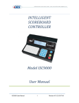
1551 E 11th Street, Loveland, CO 80537 • 970-667-1000 • Fax: 970-667-1032 • www.coloradotime.com
INSTRUCTIONS
Introduction
Congratulations on the purchase of your new electronic scoreboard. Your scoreboard is state of the art and designed
along with detailed information regarding your particular model. If further information is required please contact
your CDS sales representative at 970-667-1000.
Service and Customer Information
In the event service is required for your scoreboard or if you wish to order replacement parts please contact your
CDS sales representative at 970-667-1000.
To aid in your discussions, we suggest that you record the following information for reference:
MODEL NUMBER:
___________________________________________________________
INSTALLATION DATE:
_______________________________________________________
CDS SALES
REPRESENTATIVE: ___________________________________________________________
CONTACT
INFORMATION: _______________________________________________________________
CONTACT
PRODUCT
SERIAL NUMBERS: ____________________________________________________________
____________________________________________________________
____________________________________________________________
____________________________________________________________
____________________________________________________________
____________________________________________________________
1551 E 11th Street, Loveland, CO 80537 • 970-667-1000 • Fax: 970-667-1032 • www.coloradotime.com
INSTRUCTIONS
Indoor Scoreboards
Your scoreboard will require a 120 VAC, 60 Hz, grounded receptacle located within 5 feet of the top-centre of the scoreboard. Optional 230VAC, 60Hz, is also available. Typically the outlet will be a dedicated
15 Amp circuit. Refer to the model specific information provided in this package for the exact current load
for your scoreboard. FIGURE 1 illustrates a generic installation including a controller. Seek the service of
a qualified electrician to ensure the electrical installation meets all local electrical codes. CDS assumes no
responsibilities for installations done by others.
NOTE: On scoreboards with the cULus mark, the scoreboard does not come equipped with a power
cord as these units must be permanently wired in.
Data cabling for the scoreboard is available in standard lengths (connectors factory installed), or as a kit
for custom lengths (connectors installed on site). See the DATA CABLING section for more information.
Wall mounting is the preferred method of installation. When determining the installation location, ensure
shipping. Remove and re-install the brackets so that the mounting holes are exposed past the edge of the
scoreboard. Lifting eyebolts are provided on the top of the scoreboard to facilitate lifting of the unit to its
type of fasteners selected should be suitable for the type of wall construction and have sufficient capacity
to support the scoreboard. CDS recommends using 3/8” fasteners. Detailed information regarding mounting locations and fasteners recommendations for your scoreboard model is provided in the documentation
attached.
1551 E 11th Street, Loveland, CO 80537 • 970-667-1000 • Fax: 970-667-1032 • www.coloradotime.com
A
B
C
D
SCOREBOARD
PIN G - SHIELD
PIN 4 - BLACK (RS -)
PIN 3 - WHITE (RS +)
3
PIN 2 - COM (DC CONTROLLER ONLY)
SEEK THE SERVICE OF A QUALIFIED ELECTRICIAN TO ENSURE ALL
WIRING MEETS APPLICABLE ELECTRICAL CODES.
4
NC4MX
CN137D
3
PIN 1 - V+ (DC CONTROLLER ONLY)
->ELECTRICAL: 15A, 120VAC/230VAC, 60Hz, GROUNDED RECEPTACLE
LOCATED WITHIN 5 FEET OF SCOREBOARD'S TOP EDGE.
REFER TO MODEL SPECIFIC DOCUMENTION FOR EXACT CURRENT LOAD
->CONTROLLER DATA: SHIELDED, 2 TWISTED PAIR, 24 GUAGE DATA WIRE
AVAILABLE PRE-ASSEMBLED IN STANDARD LENGTHS OR IN KIT FORM
FOR CUSTOM LENGTHS
ALL WIRING LOCATED ON TOP CENTRE OF SCOREBOARD.
SCOREBOARD WIRING:
APPROX. LENGTH - 5 FEET
GROUNDED ELECTRICAL CORD
OES BIN#
NEUTRIK PART#
4 POS. MALE CONNECTOR
GENERIC INDOOR INSTALLATION
4
SOLDER CUP VIEW
PIN 3
PIN 4
PIN G
PIN 2
PIN 1
2
2
7
4
1
CLEAR
8
5
2
0
ENTER
9
6
3
1
THIRD ANGLE PROJECTIONS
APPROVED BY:
CHECKED BY:
OES, INC. CLAIMS PROPERTY RIGHTS TO THE MATERIAL
DISCLOSED HEREIN. THIS DRAWING INCLUDES
UNPUBLISHED PROPRIETARY MATERIAL DEVELOPED BY
OES, INC. AND AS SUCH IS NOT TO BE COPIED,
REPRODUCED OR USED IN ANY WAY WITHOUT PRIOR
WRITTEN AUTHORIZATION FROM OES, INC.
NC4FX
CN137C
PIN G - NO CONNECTION
PIN 4 - BLACK (RS -)
PIN 3 - WHITE (RS +)
PIN 2 - COM (DC CONTROLLER ONLY)
PIN 1 - V+ (DC CONTROLLER ONLY)
OES BIN#
NEUTRIK PART#
SCALE
B
SIZE
05/20/03
DATE
N/A
1
DRAWN BY
INFORMATION ONLY
USAGE
800-INSTALL-002
FILENAME
JPG
PAGE
05/20/2003
INIT DRAWING DATE
OES ELECTRONIC SCOREBOARDS
GENERIC OUTDOOR INSTALLATION
DESCRIPTION
Fax. (519) 652-3795
Email [email protected]
Tel. (519) 652-5833
4056 Blakie Road, London, ON N6L 1P7
OES, Inc.
DC CONTROLLER RECEIVES POWER FROM SCOREBOARD
AC AND RF CONTROLLERS WILL REQUIRE AN 120VAC
RECEPTACLE NEAR CONTROLLER LOCATION.
NOTICE TO PERSON RECEIVING THIS DRAWING AND
TECHNICAL INFORMATION:
AUTH.
4 POS. FEMALE CONNECTOR
CONNECT CONTROLLER DATA WIRE AS PER
PIN OUTS DETAILED ABOVE.
CONTROLLER WIRING:
ISC85X CONTROLLER
PIN 3
PIN 4
INITIAL DESIGN
SOLDER CUP VIEW
PIN 2
PIN 1
PIN G
DESCRIPTION
REVISION
A
1 OF 1
APVD
A
REV
A
B
C
D
INSTRUCTIONS
1551 E 11th Street, Loveland, CO 80537 • 970-667-1000 • Fax: 970-667-1032 • www.coloradotime.com
INSTRUCTIONS
Installation
Outdoor Scoreboards
Your scoreboard will require a 120 VAC, 60 Hz, grounded electrical feed. Typically the feed will be a dedicated 20
Amp circuit. Optional 230VAC, 60Hz, is also available. Refer to the model specific information provided in this
package for the exact current load for your scoreboard. FIGURE 2 illustrates a generic installation including a controller. CDS recommends using ONLY grounded metal conduit. Seek the service of a qualified electrician to ensure
the electrical installation meets all local electrical codes. CDS assumes no responsibilities for installations done by
others. Data cabling for the scoreboard is available as a kit for installation with the grounded conduit (connectors
installed on site). See the DATA CABLING for more information.
Pole mounting is the preferred method of installation. Seek the service of a qualified contractor to ensure the strucCD
scoreboard is shipped with mounting brackets which will require installation prior to mounting the scoreboard. All
necessary hardware required to mount the brackets to the scoreboard is provided with your new scoreboard. Lifting eyebolts are provided on the top of the scoreboard to facilitate lifting of the unit to its final installation location.
suitable for the type of construction and have sufficient capacity to support the scoreboard. CDS recommends using
½”, grade 8 fasteners. Detailed information regarding mounting locations and fastener recommendations for your
scoreboard model is provided in the documentation attached.
1551 E 11th Street, Loveland, CO 80537 • 970-667-1000 • Fax: 970-667-1032 • www.coloradotime.com
A
B
C
D
3
CABLING ROUTED
THROUGH GROUNDED
METAL CONDUIT
4
SEEK THE SERVICE OF A QUALIFIED ELECTRICIAN TO ENSURE ALL
WIRING MEETS APPLICABLE ELECTRICAL CODES.
RECOMMEND GROUNDED METAL CONDUIT FOR ALL WIRING.
->ELECTRICAL: 120VAC/230VAC, 60Hz, DEDICATED CIRCUIT
REFER TO MODEL SPECIFIC DOCUMENTATION FOR
EXACT CURRENT LOAD
->CONTROLLER DATA: SHIELDED, 2 TWISTED PAIR, 24 GUAGE DATA WIRE
ALL WIRING LOCATED WITHIN WEATHERPROOF ALUMINUM JUNCTION BOX
LOCATED ON REAR OF SCOREBOARD.
SCOREBOARD WIRING:
3
AC AND DATA CABLING MAY BE SEPARATED INTO INDIVIDUAL JUNCTION BOXES DEPENDING ON MODEL
BLACK - COM (DC CONTROLLER ONLY)
SHIELD - EARTH
BLACK - RSRED - V+ (DC CONTROLLER ONLY)
WHITE - RS +
SCOREBOARD DATA CABLE
GREEN - EARTH
BLACK - LINE (120VAC)
WHITE - NEUTRAL (120VAC)
SCOREBOARD AC CABLE
REAR OF SCOREBOARD
GENERIC OUTDOOR INSTALLATION
4
2
2
PIN 3
PIN 4
CLEAR
7
4
1
8
5
2
0
9
6
3
ENTER
NC4FX
CN137C
PIN G - NO CONNECTION
PIN 4 - BLACK (RS -)
PIN 3 - WHITE (RS +)
OES, INC. CLAIMS PROPERTY RIGHTS TO THE MATERIAL
DISCLOSED HEREIN. THIS DRAWING INCLUDES
UNPUBLISHED PROPRIETARY MATERIAL DEVELOPED BY
OES, INC. AND AS SUCH IS NOT TO BE COPIED,
REPRODUCED OR USED IN ANY WAY WITHOUT PRIOR
WRITTEN AUTHORIZATION FROM OES, INC.
NOTICE TO PERSON RECEIVING THIS DRAWING AND
TECHNICAL INFORMATION:
THIRD ANGLE PROJECTIONS
SCALE
B
SIZE
05/20/03
DATE
N/A
1
DRAWN BY
INFORMATION ONLY
USAGE
800-INSTALL-001
FILENAME
JPG
PAGE
05/20/2003
INIT DRAWING DATE
OES ELECTRONIC SCOREBOARDS
GENERIC OUTDOOR INSTALLATION
DESCRIPTION
Fax. (519) 652-3795
Email [email protected]
Tel. (519) 652-5833
4056 Blakie Road, London, ON N6L 1P7
OES, Inc.
DC CONTOLLER RECIEVES POWER FROM SCOREBOARD
AC AND RF CONTROLLERS WILL REQUIRE A 120VAC
RECEPTACLE NEAR CONTROLLER LOCATION.
APPROVED BY:
CHECKED BY:
AUTH.
PIN 2 - COM (DC CONTROLLER ONLY)
PIN 1 - V+ (DC CONTROLLER ONLY)
OES BIN#
NEUTRIK PART#
CONNECT CONTROLLER DATA WIRE AS PER
PINOUTS DETAILED ABOVE.
CONTROLLER WIRING:
ISC85X CONTROLLER
SOLDER CUP VIEW
PIN 2
PIN 1
PIN G
1
4 POS. FEMALE CONNECTOR
DESCRIPTION
INITIAL DESIGN
REVISION
A
1 OF 1
APVD
A
REV
A
B
C
D
INSTRUCTIONS
1551 E 11th Street, Loveland, CO 80537 • 970-667-1000 • Fax: 970-667-1032 • www.coloradotime.com
A
B
C
D
4
NOTE:
8001005-XXX
4
PIN 1
PIN G
PIN 4
2
PIN 1 - RED
SHIELD - PIN G
BLACK - PIN 4
PIN 4
PIN 2
PIN 1
PIN 2
3
INDICATES WIRE LENGTH IN FEET
PIN 3
PIN 3
PIN G - N/C
PIN 4 - BLACK
PIN 3 - WHITE
PIN G
2
PIN 2 - BLACK
RED - PIN 1
4
WHITE - PIN 3
3
8001005-XXX
2
BLACK - PIN 2
1
8001005-XXX
3
INITIAL DESIGN
4 POS. FEMALE CONNECTOR
4 POS. MALE CONNECTOR
DESCRIPTION
AS REQ'D
1
1
QTY
2
1
ITEM
OES, Inc.
1
THIRD ANGLE PROJECTIONS
APPROVED BY:
CHECKED BY:
UNPUBLISHED PROPRIETARY MATERIAL DEVELOPED BY
OES, INC. AND AS SUCH IS NOT TO BE COPIED,
REPRODUCED OR USED IN ANY WAY WITHOUT PRIOR
WRITTEN AUTHORIZATION FROM OES, INC.
MFG.
NEUTRIK
NEUTRIK
SCALE
B
SIZE
FILENAME
1:1
1
DRAWN BY
JPG
USE FOR CONSTRUCTION
PAGE
04/02/2003
INIT DRAWING DATE
8001005-XXX CONSTRUCTION
8001005-XXX SPEC
USAGE
PART #
MC4MX
NC4FX
9502
N/A
04/02/03
DATE
ENGINEERING SPECIFICATION
Fax. (519) 652-3795
Email [email protected]
DESCRIPTION
AUTH.
BELDON
BRADY
4056 Blakie Road, London, ON N6L 1P7
OES, INC. CLAIMS PROPERTY RIGHTS TO THE MATERIAL
DISCLOSED HEREIN. THIS DRAWING INCLUDES
Tel. (519) 652-5833
NOTICE TO PERSON RECEIVING THIS DRAWING AND
TECHNICAL INFORMATION:
2 TWISTED PAIR 24GA
1
4
3
WIRE LABEL
DESCRIPTION
REVISION
A
1 OF 1
BIN #
CN137D
CN137C
WR060B
LB005A
APVD
A
REV
A
B
C
D
INSTRUCTIONS
1551 E 11th Street, Loveland, CO 80537 • 970-667-1000 • Fax: 970-667-1032 • www.coloradotime.com
INSTRUCTIONS
Installation
Data Cabling
Data cabling can be purchased as a pre-assembled cable in set lengths or as a kit to be assembled on site.
Pre-assembled cables are available in multiple lengths of 25 feet (25ft, 50ft, 75ft, etc). Cable kits can be purchased
in any desired length. If cabling is to be routed through conduit, CDS recommends purchasing the cable kit.
FIGURE 3 outlines connection details for both. Your CDS sales representative can help you select the appropriate
cabling choice for your particular installation.
Installation Accessories
A wide range of accessories are available to you and your facility to ease installation and protect your scoreboard
investment. Products such as junction boxes and connector boxes are available to provide a professional appearance
to any installation. RF radios are available for both indoor and outdoor scoreboards to eliminate costly controller
cabling. Safety screens are available to protect the scoreboard from accidental impact. Protective bags are available
for controller storage and transport while not in use. Please contact your CDS sales representative for more information on available accessories for your scoreboard.
Model Specific Documentation
ment parts, and specific mounting details. If any further information is required please contact your CDS sales
representative at 970-667-1000.
1551 E 11th Street, Loveland, CO 80537 • 970-667-1000 • Fax: 970-667-1032 • www.coloradotime.com
1551 E 11th Street, Loveland, CO 80537 • 970-667-1000 • Fax: 970-667-1032 • www.coloradotime.com
1551 E 11th Street, Loveland, CO 80537 • 970-667-1000 • Fax: 970-667-1032 • www.coloradotime.com
1551 E 11th Street, Loveland, CO 80537 • 970-667-1000 • Fax: 970-667-1032 • www.coloradotime.com
1551 E 11th Street, Loveland, CO 80537 • 970-667-1000 • Fax: 970-667-1032 • www.coloradotime.com
1551 E 11th Street, Loveland, CO 80537 • 970-667-1000 • Fax: 970-667-1032 • www.coloradotime.com
1551 E 11th Street, Loveland, CO 80537 • 970-667-1000 • Fax: 970-667-1032 • www.coloradotime.com
INSTRUCTIONS
ISC85X Intelligent Controller
OPERATION:
To enter into configure mode on the controller:
• Turn on controller.
• Turn RUN/STOP switch to STOP position.
• Press and hold the bottom button in the fifth column on
the keypad until the configure menu appears (Button to
the left of CLEAR). This button may be blank or may
be labeled “CONFIG” or “SETUP”.
• Select desired option using the numeric keypad.
INTRODUCTION:
The ISC85x controller comes ready to use; no setup
required. All settings are pre-set at the factory
to the customer requirements. The settings can
be accessed by the operator if necessary. There
are a number of configure / set-up features within
the controller. These features include: Turning the
scoreboard off/on, setting up the sport and features
of the scoreboard, setting the time of day (TOD),
setting the contrast on the controller LCD display,
and running the scoreboard through a system of
tests.
NOTE: These configure features, including this
instruction sheet, should be kept from the standard
user and only made available to the person in
charge of the scoreboard system.
OPTIONS:
1. Board Off/On:
• This blanks the entire scoreboard. This is only required
on a few baseball scoreboard models, since the
majority will blank on their own 15 seconds after the
last communications for the controller.
2. Select Sport/Features:
• The first screen selects the sport, follow on screen
instructions.
MODEL 52xx SYSTEM NOTE:
basketball, volley ball, and
wrestling are valid selections.
MODEL 62xx SYSTEM NOTE:
Hockey is only valid selection.
1551 E 11th Street, Loveland, CO 80537 • 970-667-1000 • Fax: 970-667-1032 • www.coloradotime.com
INSTRUCTIONS
ISC85X Intelligent Controller
The next screen selects the features.
• ‘0’ indicates disabled
• ‘1’ indicates enabled
• ‘X’ means ‘0’ or ‘1’ will depend on the system
(Contact factory if clarification is required.)
Basketball
Time Out Left
Team Fouls
Player Fouls
Last Foul
Shoot Clocks
Hockey
Shots On Goal
Penaltys
Time
Player
Shot Clocks
Shift Timer
Motherboard Filler
5200
0
0
0
0
X
5210
0
1
0
1
X
5240
0
0
0
0
X
6200 / 6220
0
1
1
1
X
X
X
6210 / 6225
0
1
1
0
X
X
X
6240
0
1
0
0
X
X
X
Follow on screen instructions to properly set-up features
NOTE: Improper settings will result in the scoreboard
operating and displaying undesirably.
• Follow on screen instructions to properly set-up
the contrast.
5. Board Test:
3. TOD
• This sets up the time of day on the clocks in the
scoreboard system.
• Ensure all clocks that need to receive this setting are on
and attached to the controller through the communication
network.
• Follow on screen instructions to properly set-up TOD.
4. Contrast
• This controls the brightness / contrast of the LCD on the
controller.
• This will test the scoreboard digits.
The first test, All On, turns on everything
The other test, Rotate, has all digits counting
from 0-9, then blank
• These tests continue until you exit from the
screen and then will return to the game
displays.
• Follow on screen instructions to control the
tests.
6. Exit
• This exits the configure screens without any
changes.
1551 E 11th Street, Loveland, CO 80537 • 970-667-1000 • Fax: 970-667-1032 • www.coloradotime.com
INSTRUCTIONS
ISC85X Intelligent Controller
6.
To set PERIOD/QUARTER:
• Press PERIOD.
•
Enter period on the numeric keypad.
Press Enter.
7.
To set SCORES:
• Press HOME SCORE or GUEST SCORE.
• Enter score on numeric keypad. Press Enter.
8.
To INCREMENT SCORES:
• Press HOME SCORE or GUEST SCORE.
• Then press: +1,+2, or +3.
9.
To toggle POSSESSION between HOME/GUEST:
• Press POSS.
5240 Instructions
ISC85X
BASKETBALL
Home
Score
+1
Guest
Score
Game
Time
Int.
Mode
New
Game
Period
Bonus
0-1-2
Poss
Shot
Clock Set
/ Shift
Time
Out
Shot
Clock Reset
+2
Bonus
0-1-2
Time
Out
+3
10.
To toggle between “BONUS”: No Bonus (0); Single
Bonus (1); and Double Bonus (2).
• Press HOME BONUS or GUEST BONUS.
11.
To set TIME OUT
• Press HOME TIME OUT or GUEST TIME OUT.
• Toggles On or Off.
12.
(Optional) To set Shot Clock:
• Press SHOT CLOCK SET.
•
Enter “shot clock” length on the
numeric keypad.
Press Enter.
•
NOTE: if not using the shot clock, set the shot
clock time to zero.
13.
(Optional) To Reset Shot Clock:
• Press SHOT CLOCK RESET.
1. START/STOP the clock:
• Flip switch ON/OFF (Rocker switch on the right
side of the unit.)
2. Manual HORN:
•
Activate by pressing the push button switch on
the right side of the unit.
3. Automatic HORN:
• Horn sounds automatically when time hits 0:00.
• Horn will sound for 1.5 seconds.
4. To set TIME:
• Press GAME TIME.
•
Enter “minutes” on the numeric keypad.
Press Enter.
•
Enter “seconds” on the numeric keypad.
Press Enter.
INT.
•
Enter “tenths of seconds” on the numeric keypad.
Press Enter.
• When pressed at the end of the period, the last
entered time will appear and the period will
automatically increment.
5.
To set TIME OUT/INTERMISSION timer:
• Press INT. MODE.
•
Enter “minutes” on the numeric keypad.
Press Enter.
•
Enter “seconds” on the numeric keypad.
Press Enter.
INT.
•
To exit this mode, press INT. MODE again.
14. To set SHIFT TIMER (IF ENABLED):
NOTE: The SHIFT TIMER counts down from the set amount.
When the SHIFT TIMER is expired a one second horn will
sound, then the SHIFT TIMER will reset and start counting
down again.
•Press SHIFT.
•Enter the shift time settings in minutes using the
numeric keypad. Press ENTER.
•To edit the current running shift time Press SHIFT.
Then SHIFT again. Enter the minutes using the
numeric keypad.Press ENTER.Enter the seconds
using the numeric keypad.Press ENTER.
NOTE: On power up, the shift time will be 0:00, which leaves
it in an inactive mode which means no horns will sound.
1551 E 11th Street, Loveland, CO 80537 • 970-667-1000 • Fax: 970-667-1032 • www.coloradotime.com