1
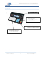
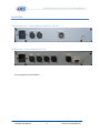
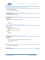
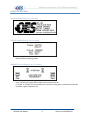
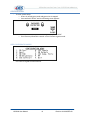
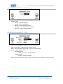
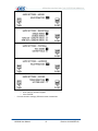
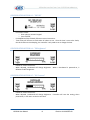
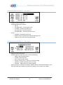
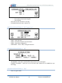
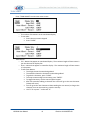
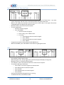
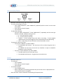
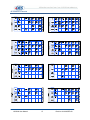
INTELLIGENT SCOREBOARD CONTROLLER Model ISC9000 User Manual ISC9000 User Manual 1 Revision A4.0 09-SEP-09 Table of Contents INTRODUCTION ...................................................................................................................................... 4 MODELS .............................................................................................................................................. 4 FEATURES ........................................................................................................................................... 4 HARDWARE............................................................................................................................................. 5 FRONT PANEL ..................................................................................................................................... 5 BACK PANEL ........................................................................................................................................ 6 Interface Details: ............................................................................................................................ 7 OPERATING INSTRUCTIONS .................................................................................................................... 8 GENERAL NOTES ................................................................................................................................. 8 POWER OFF/ON .................................................................................................................................. 8 POWER ON SEQUENCE ....................................................................................................................... 9 CONFIGURATION .............................................................................................................................. 10 CONFIGURATION OPTION #1 – “SB Test”..................................................................................... 11 CONFIGURATION OPTION #2 – “Sport”........................................................................................ 11 CONFIGURATION OPTION #3 – “SB TOD” .................................................................................... 13 CONFIGURATION OPTION #4 – “SB Brightness” .......................................................................... 13 CONFIGURATION OPTION #5 – “ISC Contrast”............................................................................. 13 CONFIGURATION OPTION #6 – “ISC Inputs” ................................................................................ 14 CONFIGURATION OPTION #7 – “SB Outputs” .............................................................................. 14 CONFIGURATION OPTION #8 – “ISC Comm. Ports” ..................................................................... 15 CONFIGURATION OPTION #9 – “RF” ............................................................................................ 15 CONFIGURATION OPTION #0 – “Exit” .......................................................................................... 15 TEAM NAMES ................................................................................................................................... 16 REGULAR GAME OPERATIONS.......................................................................................................... 17 Game Time ................................................................................................................................... 17 Saved Time ................................................................................................................................... 17 Intermission / Break / Time‐Out Timer ........................................................................................ 18 Shift............................................................................................................................................... 18 Shot Clock (Play Timer) ................................................................................................................. 19 Period ........................................................................................................................................... 19 Scores ........................................................................................................................................... 20 Penalties ....................................................................................................................................... 20 Shots on Goal (SOG) ..................................................................................................................... 21 ISC9000 User Manual 2 Revision A4.0 09-SEP-09 Time Outs Left (TOL) ..................................................................................................................... 21 Fouls ............................................................................................................................................. 21 Bonus ............................................................................................................................................ 22 Possession (POSS) / Serving.......................................................................................................... 22 Field .............................................................................................................................................. 22 Sets ............................................................................................................................................... 22 Tie‐Breaker ................................................................................................................................... 22 Match ........................................................................................................................................... 22 Corner Kicks .................................................................................................................................. 23 APPENDIX A: Specifications .................................................................................................................. 24 APPENDIX B: Warranty ......................................................................................................................... 25 APPENDIX C: Spare & Replacement Parts ............................................................................................ 26 APPENDIX D: Inserts ............................................................................................................................. 27 NOTES ................................................................................................................................................... 28 ISC9000 User Manual 3 Revision A4.0 09-SEP-09 INTRODUCTION MODELS ISC9000‐ST – Standard Version ISC9000‐PR – Professional Version ISC9000‐MI – Indoor Wireless Version ISC9000‐MO – Outdoor Wireless Version FEATURES Standard Features: Microprocessor and Quartz Crystal based, providing timing accuracy Battery Backed Memory 5.1” Full Graphic Backlit Display Full function keypad complete with 4x8 configurable insert One RS485 2‐Wire Communication Port for Game Data One USB Communication Port for Diagnostics and Upgrades Two Configurable Remote Input Ports Model Specific Features: ISC9000‐PR Additional RS485 2‐Wire Communication Port for Multi‐Controller setups One RS232 Communication Port for Game Data ISC9000‐MI Wireless Communication for Game Data (Indoor Operation) ISC9000‐MO Wireless Communication for Game Data (Outdoor Operation) Optional Features: Ethernet/Wi‐Fi Port ISC9000 User Manual 4 Revision A4.0 09-SEP-09 HARDWARE FRONT PANEL 5.1” GRAPHIC BACKLIT GAME TIME CONTROL ‐ Time running Indicator LED ‐ RUN/STOP Buttons ALPHA‐NUMERIC KEYPAD ‐ Complete with CLEAR and ENTER keys CONFIGURABLE 4x8 KEYPAD ‐ Insert slides in from left ISC9000 User Manual 5 Revision A4.0 09-SEP-09 BACK PANEL Standard Back Panel – Used on Models: ISC9000‐ST, ‐MI, ‐MO Pro Back Panel – Used on Model ISC9000‐PR See next page for interface details. ISC9000 User Manual 6 Revision A4.0 09-SEP-09 Interface Details: Power-In Module (Labeled “100-230VAc” & “1A SLO-BLO”) Input: 100‐230Vac, 50‐60Hz Fuse: 1A, 250V, SLO‐BLO, 5x20mm Remote Inputs (Labeled – “REMOTE 2” & “REMOTE 1”) Software Configurable Available Remote: OES # ISCREM‐S Controller Port (Labeled “ISC IN” & “ISC OUT”) ISC9000‐PR Only RS485 2‐Wire Mating Connectors – OES # CN138F and CN139B Pinout: Pin 3 – RS+ Pin 4 – RS‐ Game Port 1 (Labeled “GAME OUT”, XLR-4 Connector) RS485 2‐wire ISC9000‐ST, ‐MI, ‐MO Mating Connector – OES # CN137C ISC9000‐PR Mating Connector – OES # CN137D Pin out: Pin 3 – RS+ Pin 4 – RS‐ Game Port 2 (Labeled “GAME OUT”, DB9 Male Connector) ISC9000‐PR Only RS232 DTE Pin out: Pin 2 – Data Into of Controller (Should not be used, for diagnostics only) Pin 3 – Data Out of Controller Pin 5 – Ground USB Used for diagnostic and upgrades Ethernet / WI-FI Not shown, optional ISC9000 User Manual 7 Revision A4.0 09-SEP-09 OPERATING INSTRUCTIONS GENERAL NOTES ‐ ‐ ‐ ‐ Controller beeper only sounds for valid keypad presses. Keypad LED lights when game time is running. To set a numeric value: o Press the desired function key (i.e. HOME SCORE). o Enter the value on the numeric keypad. o Press “ENTER”. o In regular game mode: A cursor will appear on the value. If the cursor is on a value and there are no key presses for 10 seconds, the value will go back to pre‐cursor state and the cursor will go off. o Many game values have easy increment/decrement. To increment a value, press the function key twice. The first key press will put the cursor on the value; the second key press will increment/decrement the value by 1 and turn the cursor off. The only value that will be decremented is TOL, any other values will all be incremented. o Every value has a minimum and maximum. If a value lower than the minimum is entered, the value will be set to the minimum. If a value higher than the maximum is entered, the value will be set to the maximum. To set a non‐numeric setting value: o Press “CLEAR” to toggle through available values. o Press “ENTER” to accept. o Often, most of these values have on‐screen instructions. POWER OFF/ON ‐ ‐ ‐ The controller is not equipped with a Power Switch. To turn controller completely off, unplug power cord. To turn controller operations off through the keypad, press and hold “OFF” until the following screen will appear: ‐ ‐ Communication stops to scoreboard. Press any key; this will bring the controller to Power On sequence. ISC9000 User Manual 8 Revision A4.0 09-SEP-09 POWER ON SEQUENCE SPLASH SCEEN (Displays for 2 seconds) ‐ Shows OES contact information. STATUS SCREEN (Displays for 2 seconds) ‐ ‐ Shows program revision and date. Shows controller operating mode. MEMORY RECALL (Displays up to 5 seconds) ‐ ‐ ‐ ‐ Press “CLEAR” to start a new game. Press “ENTER” to use game data saved from last time unit was on. If “CLEAR” or “ENTER” are not pressed within 5 seconds, a new game is automatically selected. Proceeds to game mode after this. ISC9000 User Manual 9 Revision A4.0 09-SEP-09 CONFIGURATION ‐ To enter system setup: o Ensure in normal game mode and game time is stopped. o Press and hold “SETUP” until the following screen appears: o o Enter password (5833) on numeric keypad and press “ENTER”. If an incorrect password is entered – unit will return to game mode. USER CONFIGURATION MENU ‐ Use numeric keypad to make selection. ISC9000 User Manual 10 Revision A4.0 09-SEP-09 CONFIGURATION OPTION #1 – “SB Test” ‐ ‐ Follow on‐screen instructions. Available Tests: o ALL OFF – blanks all displays o ALL ON – turns on all displays o ROTATE – rotates through numbers o LOCATION – control board driver number o OUTPUTS – rotates through outputs CONFIGURATION OPTION #2 – “Sport” ‐ ‐ ‐ ‐ ‐ ‐ Follow on‐screen instructions. Protocol – Not editable, for reference only, set at factory. Sport – Select Sport. Toggles through available sports. Mode – Select controller setup mode – single‐ or multi‐controller. Options – Sport specific options. o Standard Protocol Hockey & Lacrosse – Penalty Numbers o Custom Protocol Football – Protocol locations After this Sport setup screen, another game settings screen may appear for a couple of sports. ISC9000 User Manual 11 Revision A4.0 09-SEP-09 ‐ ‐ For numeric values: o Enter value on numeric keypad. o Press “ENTER”. For none numeric settings, follow on‐screen instructions. ISC9000 User Manual 12 Revision A4.0 09-SEP-09 CONFIGURATION OPTION #3 – “SB TOD” ‐ ‐ ‐ For numeric values: o Enter value on numeric keypad. o Press “ENTER”. For AM/PM and Day of Week, follow on‐screen instructions. Time of Day will be sent to clocks when all values are set. Once the time is sent to the clocks, the clocks take over timekeeping, the controller is only used to set or change the time. CONFIGURATION OPTION #4 – “SB Brightness” ‐ ‐ Follow on‐screen instructions. When adjusted, scoreboard will change brightness. When a scoreboard is powered on, it defaults to 100% brightness. CONFIGURATION OPTION #5 – “ISC Contrast” ‐ ‐ Follow on‐screen instructions. When adjusted, scoreboard will change brightness. Controller will save the setting, when powered on, it will return to the last set value. ISC9000 User Manual 13 Revision A4.0 09-SEP-09 CONFIGURATION OPTION #6 – “ISC Inputs” ‐ ‐ ‐ Follow on‐screen instructions. Available Wired Remote options: o NO I/O o I/P‐GAME TIME – Controls game timer. o I/P‐HORN – Sounds main game horn. o I/P‐SHOT TIME – Controls shot timer. o I/P‐SHOT RESET – Controls shot timer reset. ISC‐HH o Available in Standard Protocol only. o Used for time start/stop/reset and incrementing scores. o COM1 must be set RF (See Setup Option #8). CONFIGURATION OPTION #7 – “SB Outputs” ‐ ‐ ‐ ‐ Follow on‐screen instructions. Available options are No O/P or O/P 1‐4 for the following: o HORN – Main Scoreboard Horn. o SC HRN – Shot Clock Horn. o EOP – End of period indicator. o ACTIVE – System active – will be on if communicating. o TIME ON – Output will be one if timer running. o TIME OFF – Output will be on if timer stopped. Anytime the Sport or Protocol are edited – default values for Scoreboard Outputs are set. After done editing the outputs, the next screen appears to set output time lengths. ISC9000 User Manual 14 Revision A4.0 09-SEP-09 ‐ ‐ ‐ To set each value: o Enter value on the numeric keypad. o Press “ENTER”. Note that the value entered is in seconds. For Manual Horn only, enter a value of “0”. CONFIGURATION OPTION #8 – “ISC Comm. Ports” ‐ ‐ ‐ ‐ ‐ Follow on‐screen instructions. COM1 – Game data port. COM2 – Controller‐Controller communications. COM3 – Game Data or Diagnostics. COM3 GAME – if set to “ON”, sends game data out. CONFIGURATION OPTION #9 – “RF” ‐ ‐ ‐ If no radio attached, unit will return to game mode. TECHNOLOGY – This value is read from the radio, either HC or SC will appear. CHANNEL & ADDRESS – Usually are set to the same value. Maximums on CHANNEL are per technology. CONFIGURATION OPTION #0 – “Exit” ‐ Returns to game mode. ISC9000 User Manual 15 Revision A4.0 09-SEP-09 TEAM NAMES ‐ Press “TEAM NAMES” to enter team name screen ‐ Display Size o The number of characters on the scoreboard display. o To set value: Enter value on numeric keypad. Press “ENTER”. ‐ Team Names: o Full – Names that appear on scoreboard display. The maximum length of these names is per the value set for Display Size. o Short – Names that appear on controller display. The maximum length of these names is 5 characters. o To edit Team Names: The hi‐light shows the name being edited. The underline shows the character location being edited. To go back a character, press “CLEAR”. To accept a name and go to next name, press “ENTER”. To toggle characters, use the numeric/alpha keypad. After one second of editing a character the cursor will go to the next character (A beep will occur). You can go to the next character without waiting the one second, as long as the character is not on the same key, press the new key. Use “0” for a space “ “ and a zero “0”. ISC9000 User Manual 16 Revision A4.0 09-SEP-09 REGULAR GAME OPERATIONS Game Time ‐ ‐ ‐ ‐ ‐ ‐ ‐ Time on the scoreboard display will show mm:ss, where mm is minutes and ss is seconds. In all sports except football and soccer, when game time is less than one minute the display will show ss.t, where ss is seconds, and t is tenths of a second. Maximum value is: 99 minutes, 59 seconds, and 99 hundredths of a second. Time will count down to 0:00.0. In soccer, the time can be set to count up. The limit on up timer is per setting in configuration. To set Game Time: o All timers must be stopped. o Press “GAME TIME”. o Enter Minutes value on numeric keypad. o Press “ENTER”. o Enter Seconds Value on numeric keypad. o Press “ENTER”. o Enter Hundredths of Seconds on numeric keypad. o Press “ENTER”. If “GAME TIME” is pressed when time is running, the display will show the screen with game time, but the cursor will not display for editing. If game timer is started while editing, the cursor will disappear and the game time will revert back to previous setting. If GAME TIME is pressed at the end of a period, the last set time will reload and period will increment. Saved Time ‐ ‐ Used to recall times from the last game time stoppage. Game time, and if applicable shot clock and penalties times are recalled. To recall saved times: o Press and hold “SAVED TIME” until saved times appear. ISC9000 User Manual 17 Revision A4.0 09-SEP-09 Intermission / Break / Time‐Out Timer ‐ ‐ ‐ ‐ ‐ ‐ This timer can be used for intermissions, time outs, and any kind of break timer. Any other timers, like penalty and shot clock, do not operate while using this break timer. While in this mode, the controller screen will show the timer value in the upper left and the scoreboard game time display will show this value. Maximum value is: 99 minutes and 59 seconds. To set Int. Mode time: o All timers must be stopped. o Press “INT MODE”. The last set time will appear. If this is okay, press “ENTER” twice. If not okay: • Enter Minutes value on numeric keypad. • Press “ENTER”. • Enter Seconds value on numeric keypad. • Press “ENTER”. Use game time switch to count down the INT MODE timer. While in INT MODE, press “INT MODE” to exit back to regular game mode. Shift ‐ ‐ ‐ ‐ ‐ ‐ ‐ ‐ This timer is repetitive, counts down from a set time, sounds game horn, than repeats. Not available in PRO Protocol setup. While using this timer, the top right of the controller display will display running timer. Maximum value is: 9 minutes and 59 seconds. The “Shift Set” value is the value the shift time is reset to once it expires. To set either Shift Set or Shift value: o Press “SHIFT” until cursor appears on desired value. o Enter Minute value on numeric keypad. o Press “ENTER”. o Enter Seconds value on numeric keypad. o Press “ENTER” Shift timer will operate when game timer is running. To disable Shift Time, set Shift Set to 0:00. ISC9000 User Manual 18 Revision A4.0 09-SEP-09 Shot Clock (Play Timer) ‐ ‐ ‐ ‐ Maximum value (All settings and current time) is : 99 seconds. To set the two settings or current o Press “SHOT CLOCK SET” (“PLAY TIMER SET”) repeatedly until the cursor is on the value to be edited. o Enter value on numeric keypad. o Press “ENTER”. To select the reset type. o Press the “SHOT CLOCK SELECT” (“PLAY TIMER SELECT”) repeatedly until the reset type desired is selected. Different reset types are: A – sets shot clock to A setting B – sets shot clock to B setting TOGGLE – if clock running, resets shot clock to A setting. If clock stopped, repeated reset presses will toggle the shot clock between the A and B setting. LAST – if clock stop, will reset shot clock to last value before a reset To operate the Shot Clock Timer o If no input is enabled to “I/P‐SHOT TIMER”: For basketball and lacrosse – the shot timer will run when the game time is running. For football the shot timer can not be run, therefore an input is needed for football to run the shot clock. o If there is an input enabled to “I/P‐SHOT TIMER”: The input must be on for shot clock to run. For basketball and lacrosse – the game timer must also be on. Period ‐ ‐ ‐ ‐ Maximum value is: 9. To set Period: o Press “PERIOD”. o Enter value on numeric keypad. o Press “ENTER”. To increment Period: o Press “PERIOD” twice. o Note in volleyball: Incrementing period will also put current scores in appropriate Sets value and then clear for next game. Note: See Game Time for automatic incrementing of the period value. ISC9000 User Manual 19 Revision A4.0 09-SEP-09 Scores ‐ ‐ ‐ Maximum value is: 199. To set a team’s Score: o Press “HOME SCORE” or “GUEST SCORE” o Enter value on numeric keypad. o Press “ENTER”. To increment a team’s Score: o Press desired teams increment score button. For example “HOME SCORE +1” will increment home score by 1. o Note in tennis: If Tie‐Breaker is set – scores will increment by 1. If Tie‐Breaker is not set – scores will be 15,30,40, and Advantage. Penalties - - Hockey / Lacrosse: o The controller allows input of four penalty times per team. Only the penalty times 1 & 2 are active when the game time is running. Penalty times 3 & 4 will become active and shift up into penalties 1 & 2 when the active 1 & 2 penalties expire. o The maximum Player Number is 99. o The maximum Penalty Minutes is 99, but the message protocol only sends out the last digit of minutes. So if the penalty time is 12:23, the scoreboard display will only show 2:23. o The maximum Penalty Seconds is 59. o To enter a penalty: Press either “HOME PENALTY” or “GUEST PENALTY”. The first key pressed will put the cursor on the first empty penalty location. When the same button is pressed repeatedly, the controller advances between the 4 penalties. For each penalty, enter values of the player number, penalty minutes, and seconds on the numeric keypad and press “ENTER” after each. o To clear a penalty: While on any value of the penalty to be deleted, press the “CLEAR” button. This will clear the entire penalty and shift any lower penalties up. o HOLD PENALTY Feature If this is turned on, any penalty entered in Penalty 3 & 4 will not shift up when either or both Penalty 1 & 2 expired. Needs to be enabled in Sport Configuration To toggle OFF/ON, press “HOLD PENALTY”. A small HOLD box will appear beside both team’s penalty 3&4. Soccer: o o o Maximum value is: 99. To set a team’s Penalty: Press either “HOME FOULS” or “GUEST FOULS”. Enter value on numeric keypad. Press “ENTER”. To increment a team’s Penalty: Press either “HOME FOULS” or “GUEST FOULS” twice. ISC9000 User Manual 20 Revision A4.0 09-SEP-09 Shots on Goal (SOG) - - Maximum value is: 99. To set a team’s SOG: o Press either “HOME SHOTS” or “GUEST SHOTS”. o Enter value on numeric keypad. o Press “ENTER”. To increment a team’s SOG: o Press either “HOME SHOTS” or “GUEST SHOTS” twice. OR o Press either “HOME SHOTS +1” or “GUEST SHOTS +1”. Time Outs Left (TOL) ‐ ‐ ‐ ‐ ‐ ‐ ‐ All sports that have TOL have one value except basketball, it has two. For STANDARD protocol, an indicator on the scoreboard will illuminate for the time set in game settings under Sport Configuration. For PRO protocol, the indicators are displayed per the program in the scoreboard and not controlled by the time set in game settings. Maximum value of first TOL: 9; For basketball’s second TOL: 3. To set a team’s first TOL value: o Press either “HOME TOL” or “GUEST TOL”. o Enter value on numeric keypad. o Press “ENTER”. To set a team’s second TOL value: o Press either “HOME TOL” or “GUEST TOL”. o Press “ENTER”. o Enter value on numeric keypad. o Press “ENTER”. To decrement a team’s first TOL value: o Press either “HOME TOL” or “GUEST TOL” twice. To decrement a team’s second TOL value: o Press either “HOME TOL” or “GUEST TOL”. o Press “ENTER”. o Press the same “HOME TOL” or “GUEST TOL” again. Fouls ‐ ‐ ‐ Maximum value is: Per the Double Bonus setting in Game Settings. To set a team’s Fouls: o Press either “HOME FOULS” or “GUEST FOULS”. o Enter value on numeric keypad. o Press “ENTER”. To increment a team’s Fouls: o Press either “HOME FOULS” or “GUEST FOULS” twice. ISC9000 User Manual 21 Revision A4.0 09-SEP-09 Bonus ‐ Automatically displayed per other teams’ fouls value and the bonus settings in Game Settings. Possession (POSS) / Serving ‐ Press “POSS” / “SERVING” to toggle between HOME and GUEST. Field ‐ ‐ ‐ ‐ ‐ ‐ For Football only. Field values – Down, Yards to go, Ball On. With cursor on Field Position End, use CLEAR to toggle. Press “BLANK FIELD” to blank out all field values. Scoreboard will not update any of the field values if the cursor is on any of the field values. To automatically calculate down and distance on a standard play (No penalties or turnovers), press “AUTO FIELD”, enter ball on data. The POSS value needs to be properly used. Sets ‐ ‐ ‐ ‐ For Tennis and Volleyball. Maximum value is: 99. To set any Sets value: o Press “SETS”. o Press “ENTER” until cursor showing on value to edit. o Enter value on numeric keypad. o Press “ENTER”. See note in Period section about automatic setting of Sets value. Tie‐Breaker ‐ ‐ For Tennis only. Press “TIE BREAKER” to toggle between OFF/ON. Match ‐ ‐ ‐ For Wrestling only. Maximum value is: 255. To set Match: o Press “MATCH”. o Enter value on numeric keypad. o Press “ENTER”. ISC9000 User Manual 22 Revision A4.0 09-SEP-09 Corner Kicks ‐ ‐ ‐ ‐ For Soccer only. Maximum value is: 99. To set a team’s Corner Kicks: o Press either “HOME C.K.” or “GUEST C.K.”. o Enter value on numeric keypad. o Press “ENTER”. To increment a team’s Corner Kicks: o Press either “HOME C.K.” or “GUEST C.K.” twice. ISC9000 User Manual 23 Revision A4.0 09-SEP-09 APPENDIX A: Specifications Electrical Voltage supply Physical 100‐240VAC, 50‐60Hz, 1A 320mm x 210mm x 100mm (12.50” x 8.25” x 4.00”) 2kg (4.4lb) 0 to 50°C (32 to 122°F) Dimensions – W x D x H Weight Operating Temperature Wireless (ISC9000‐MI & ISC9000‐MO) Frequency Technology Power Output Range Certification ISC9000 User Manual 902‐928Mhz Spread Spectrum (Standard) Single Channel (Optional) ISC9000‐MI – 4mW ISC9000‐MO – 100mW ISC9000‐MI ‐ 300’ Indoor, 1000’ Outdoor ISC9000‐MO – 1500’ Indoor, Up to 7miles w/dipole antenna Radio OEM Module approved under FCC Part 15.247 and Industry Canada. Contact factory for more details. 24 Revision A4.0 09-SEP-09 APPENDIX B: Warranty OES Inc. warranty covers parts and labour for a period of five year from date of delivery. The warranty is limited to the repair of OES, Inc. products only. Any warranty repair performed during the warranty period does not extend the warranty period. OES Inc. warrants the product to be free from defects in materials and workmanship under normal use and service, but OES’s obligations are limited to the repair and replacement of the parts shown to be defective at the time of shipment. OES’s liability shall not exceed the contract price for the goods claimed to be defective and OES shall not be liable for any special or consequential damages. OES products returned for repair that are damaged by misuse, abuse, negligence, or accident (all determined by OES) will have the warranty voided and all repair charges will be paid by the customer. All goods shall be returned prepaid to OES, Inc., including customs brokerage charges if applicable. OES, Inc. Service Procedure During Warranty Period In House Repairs - call OES for Return Authorization Number, then send product back prepaid. Warranty repairs will be performed at no charge (parts and labour) Goods returned from outside of Canada require customs documentation. The notation “Canadian Goods Returned” is required on customs documentation when returning OES products. If warranty is voided (OES, Inc. to determine) repairs will be charged at current OES rates. Warranty repairs will be shipped back prepaid. Applicable taxes are extra. Duty and brokerage charges for repairs shipped outside of Canada are extra. On Site Service - call OES to request a Service Technician. Warranty covers parts and labour, warranty status to be determined by Service Technician on site. Mileage will be charged at current OES rate. Travel expenses and applicable taxes are extra. OES does not cover costs of any on site work performed by others. OES, Inc. Service Procedure After Warranty Period In House Repairs - call OES for Return Authorization Number, then send product back prepaid. Goods returned from outside of Canada require customs documentation. The notation “Canadian Goods Returned” is required on customs documentation when returning OES products. Parts and labour will be charged at current OES rates. Shipping and applicable taxes are extra. Duty and brokerage charges for repairs shipped outside of Canada are extra. On Site Service - call OES to request a Service Technician. Parts, labour and mileage will be charged at current OES rates. Travel expenses and applicable taxes are extra. ISC9000 User Manual 25 Revision A4.0 09-SEP-09 APPENDIX C: Spare & Replacement Parts Description Fuse Fuse Draw Insert Power Cord Keypad / LCD Cover Feet Antenna Connector – 4 pin XLR Female Connector – 4 pin XLR Male Connector – 5 pin XLR Female Connector – 5 pin XLR Male Connector – DB9 Female Connector – DB9 Shell Cable – NULL Modem Cable – Controller Comm – 8’ Cable – Controller Comm – 25’ Cable – Controller Comm – 50’ ISC9000 User Manual Part # FS127A CN143B HW179B EN070C HW184B XF371M CN137C CN137D CN138F CN139B CN251A CN290A AU008A 8001005008 8001005025 8001005050 26 Revision A4.0 09-SEP-09 APPENDIX D: Inserts ISC9000 User Manual 27 Revision A4.0 09-SEP-09 NOTES For complete engineering and technical support, contact: 4056 Blakie Road London, Ontario, CANADA N6L 1P7 Telephone: (519) 652‐5833, FAX: (519) 652‐3795 e‐mail: oes@oes‐inc.com ISC9000 User Manual 28 Revision A4.0 09-SEP-09