1
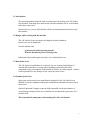
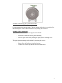
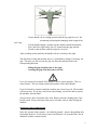
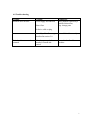
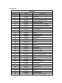
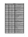
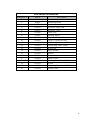
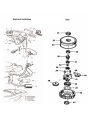
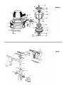
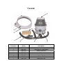
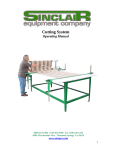
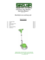
390 Surface Prep Machine
Operating Manual
October 31, 2005
Read before use and keep safe
Table of Contents
1.0
2.0
3.0
4.0
5.0
6.0
7.0
Technical Data
Safety
Safety Instructions
Maintenance
Use
Trouble Shooting
Schematics
Page 2
Page 2
Page 2
Page 4
Page 4
Page 6
Page 7
(800) 624-2408 (530) 626-9386 Fax (530) 626-5144
6686 Merchandise Way Diamond Springs, Ca 95619
www.sineqco.com
1.0 Technical data/technical description
Power supply
Power consumption
No-load speed
Sound pressure level
Sound energy level
Hand/Arm-Vibration
Weight
110V AC
1300W
154 / min.
54 dB(A)
67 dB(A)
4.5 m/s2
97 lbs.
Includes:
390 Grinding Machine, Tool Kit,
Operation Manual
2.0 Safety
The Sinclair 390 Surface Prep is state of the art designed and meets all standard
safety requirements.
3.0 Safety Instructions
Disconnect the power supply before any maintenance is carried out.
Use only recommended mounting discs and brushes. The mounting discs must have a
plain surface.
Use only genuine Sinclair discs and brushes. Other parts could affect the safety of the
machine.
Maintenance should be undertaken only by qualified personnel. Use only genuine
Sinclair spare parts. Always remove the disc and brushes before transporting the
machine. Use only appropriate detergent liquids.
Check the power cord and the plug before starting. Both of them must be in
perfect condition, the insulation must not be damaged.
CAUTION!!! Always wear ear and eye protectors! CAUTION!!!
Using this machine without ear and eye protectors may jeopardize or harm your
health. It may harm especially your ears and increase the risk of an accident.
PLEASE READ DETAILED SAFETY INSTRUCTIONS ON COLORED
SHEET BEFORE USING MACHINE!
2
3.1 Introduction
This operating manual should be used to get the most benefit from your 390 Surface
Prep machine. Following these instructions will both extend the life of your machine
and reduce repair costs.
Please make sure you are fully familiar with the operating instructions before using
this machine.
3.2 Danger while working with the machine
The 390 Surface Prep is designed to the highest technical standards.
Incorrect use can be dangerous!
Use this machine only
- As instructed in this operating manual
- With the machine in perfect working order
Disturbances that could impair safety have to be eliminated at once.
3.3 Restriction of use
The 390 Surface Prep Machine is exclusively for wet cleaning and polishing of
resilient and textile floor coverings and for grinding pavement and leveling
compounds in dry environments. It should not be used for any other purpose. Sinclair
is not responsible for any damage or loss caused by incorrect use.
3.4 Genuine Spare Parts
Spare parts and accessories are manufactured uniquely for the 390 Surface Prep
Machine. It must be emphasized that parts obtained from unauthorized sources must
not be used.
Sinclair Equipment Company cannot be held responsible for the performance of
or any damage arising from the use of machines in which genuine spare parts have
not been used.
This is particularly important with mounting discs, disc and brushes.
3
4.0 Maintenance
The 390 Surface Prep machine is virtually maintenance free.
The roller bearing and gearbox need not to be lubricated.
Mounting and changing the paper bags of the vacuum unit
The vacuum unit can be used with paper bags or with the enclosed textile bag.
-
release and pull the cover of the vacuum unit upwards
insert paper bag
remount the cover
mount the vacuum ring from the lower side of the machine
connect the vacuum ring with the vacuum unit with the tubes
connect the power cord of the vacuum unit with the grinding machine
5.0 Use
Getting started
The 390 Surface Prep is shipped in two separate boxes. Mount the handle with four
screws, safety washers and nuts to the machine (Pos. 16).
Connect the power cord of the handle with the machine.
Mount the handle with the cable entry (5) backwards (towards the user).
Otherwise the machine will not operate.
4
Assembly of mounting discs, pads and brushes
Lay the machine down on the handle. Thus the support of the discs is accessible. Put
the mounting disc on the actuation and lock it by turning anti-clockwise.
Assembly of the vacuum unit
Assemble the vacuum unit with two supports to the handle.
-
insert lower connector into the plastic mounting
lock the upper connector by shifting the upper plastic mounting down
The upper plastic mounting can be shifted by loosening the screws.
-
Mount discs and brushes as described in item
Connect the vacuum ring and the vacuum with the tubes
5
-
Put the handle (2) in working position with the big, right lever (1). We
recommend positioning the handgrip in the height of the
-
Lift the handle slightly, to make sure the machine stands horizontally.
Move the left or right safety lock (3) located onto the grip inwards.
Switch on the machine with the respective lever (4).
user’s hip.
After switching on the machine, the handle will move shortly to the right.
The direction in which the machine moves, is controlled by lifting or lowering the
grip. The more you lift or lower the grip, the faster the machine runs to the
corresponding direction.
-
lifting the grip: machine runs to the right
lowering the grip: Machine runs to the left
Lever (4) can only be actuated, if the handle is not in vertical position. This is a
safety feature! The user cannot control the machine with vertical handle.
If you feel unsafe or cannot control the machine just release lever (4). The machine
will stop at once. If you have carried out some training, you will be able to operate
the machine with one hand.
Always remove discs or brushes after work. Remove also the cleaning tank, if one
has been used. Always disconnect the power cord after work or when leaving the
machine.
Operation with vacuum cleaner
Note: the vacuum cleaner cannot – on technical grounds – remove the grinding dust
from under the discs. It will always remove the fine dust. To clean the floor, use an
industrial cylinder vacuum cleaner.
6
6.0 Trouble shooting
Trouble
Machine does not start
Eventual
Power supply disconnected
Blown Fuse
Elimination
Have machine repaired by a
qualified electrician,
resp. change parts
Defective cable or plug
Switch-on lever cannot be
actuated
Assembly of handle wrong,
described in section 5.0
Assemble handle correctly
Safety lever can only be
actuated, if handle not
vertical
Lower the handle of the
machine
7
7.0 Schematics
MACHINE
Schematic #
Part #
Description
1
021625
Top Cover + Motor Housing
2
021626
Base Link
3
021627
Rubber Washer
4
021629
Fastening Screw for Gear
5
021628
Balancing Weight
6
021629
Fastening Screw for Weight
7
021630
Fastening Screw for Housing
8
017284
Screw 4.8 x 13
9
017283
Axle Retainer
10
021631
Wheel Axle
11
018080
Washer
12
016928
Transport Wheel
13
014849
Circlip Ring
14
014830
Washer
15
021633
Wheel Cover
16
014761
Screw
17
015478
Screw Nut for Fan Wheel
18
015481
Washer
19
015480
Fan Wheel
20
015481
Screw M4 x 12
22
015483
Centifugal Switch
23
018417
Isolation Ring
24
018412
Stator 53 (110V/60Hz)
25
015485
Isolation Paper
26
015487
Shim
28
015486
Bearing 6002
29
015488
Rotor (110V/60Hz)
30
015489
Bearing E 20
31
015485
Isolation Paper
32
033964
Complete Gear
33
021634
Drive Hub
34
021635
Spacer
35
015401
Drive Hub Plate
36
014760
Screw for Hub M8 x 20
8
HANDLE
Schematic #
Part #
Description
1
015439
Screw
2 & 11
014193
Front & Rear Pistol Stock
3
015440
Adjusting Lever for Shaft
4
05441
5
014814
Screw Nut
6
015442
Lever for Water Supply
7
015443
Splint-Pin
8
015444
Spacer
9
015445
Lever for Left Switch
10
015446
Ball
10.1
018611
Spacer
12
015447
Washer
13
015448
Screw for Handle Housing
14
015450
Screw for Handle
15
015450
Screw for Cover
16
015451
Screw Nut
17
014194
Safety Switch
18
015452
Spring
19
015453
Screw
20
021641
Rod for Handle
21
015455
Pull Rod for Shaft Adjustment
22
014731
Locking Screw for Joint
23
015457
Screw Nut
24
021639
Joint
26
021638
Attachment for Joint
27
014831
Shim
28
015461
Spring
29
015462
Retention Pin
30
016922
Gear Rim
31
021642
Pivot Bracket
34
015467
Pin
35
015468
Screw for Retention Pin
36
032678
Handle, Complete #1-35
37
032680
Grip, Complete #1-18
38
032681
Joint, Complete #22-24; 26-28
Lever for Right Switch
9
ELECTRICAL INSTALLATION
Schematic #
Part #
Description
1
021637
3
05493
4
015514
Switch
5
018014
Screw for Fixed Link
6
018027
Screw for Cover
7
015496
Cable Clip
8
015497
Holding Device
9
015498
Protective Rubber Sleeve
10
021659
Cable + Connector Plug
11
021624
Cable Support
12
021623
Connecting Cable 15mm
13
018419
Screw Nut
14
033965
Spare Socket
15
015502
Socket
16
018332
Screw
17
021662
Socket Cover
18
015503
Starting Condensor 156MF
19
20
015504
015505
Screw
Operating Capacitor 31.5MF
21
033962
Socket Cover
Switch Holder
Fastening Screw
10
GEAR
Schematic #
Part #
Description
31
015507
Oil Seal Washer
32
033963
Top Cover
33
018422
O-Ring
34
018237
Washer
35
015489
Bearing E20
36
018424
Lay Shaft
37
018425
Bearing 16-004
38
018426
Bearing E15
39
015508
Gear Shaft
40
015509
Gear
41
018427
Gear Holder
42
018428
Bearing 16.001
43
018429
Planetary Box
44
015510
Oil Seal Washer
45
015511
Washer
46
018219
Grup Screw M4 x 10
11
Vacuum
Schematic#
1
2
3
4
5
6
7
8
Part#
SP014038
SP014039
SP015352
SP015353
SP015354
SP015355
SP015356
SP037299
Description
Tube with branch connection
Extraction ring with brushes
Branch connection
Brushes
Adapter
Supporting cage
Suction Case
Paper Bags 5/pk
STANDARD WARRANTY
SINCLAIR EQUIPMENT COMPANY’S tools are warranted to be free of defects in workmanship
and materials for a period of one year from the date of original purchase. Should any trouble develop
during this one year period, return the complete tool, freight prepaid, to SINCLAIR’S authorized
Service Center. If inspection shows the trouble is caused by defective workmanship or materials,
SINCLAIR EQUIPMENT COMPANY will repair, or, at its option, replace without charge.
•
This warranty does not apply to malfunctions caused by damage, unreasonable use, faulty repairs
made by others, or failure to provide recommended maintenance.
•
The warranty is void if the product is altered by the original consumer purchaser, or if it is used in
a manner not recommended by the manufacturer.
•
The warranties do not cover consequential damages or transportation charges incurred with the
replacement or repair of SINCLAIR EQUIPMENT COMPANY products.
•
Not responsible for lost job or down time.
In no event shall SINCLAIR be liable for any indirect, incidental, or consequential damages from the
sale or use of the product. This disclaimer applies both during and after the term of this warranty.
SINCLAIR EQUIPMENT COMPANY disclaims liability for any implied warranties, including
implied warranties of “merchantability” and “fitness for a specific purpose”, after the one year term of
this warranty.
This warranty gives you specific legal rights, and you may have other rights which vary from state to
state. Should you have any questions, contact SINCLAIR EQUIPMENT COMPANY at (530) 6269386.
To obtain warranty service, deliver or send the complete tool, prepaid, to SINCLAIR EQUIPMENT
COMPANY. Be sure to include the following information:
•
•
•
•
Nature of failure;
Name and address of distributor where tool was purchased;
Application of tool when rendered defective; and
Proof of purchase.
To obtain individual repair parts, contact SINCLAIR EQUIPMENT COMPANY with the following
information:
•
•
•
Tool model number;
Item part number; and
Description of part.
12
Notes
13