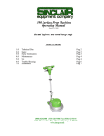
1
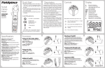
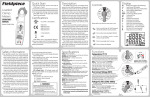
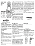
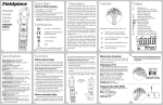
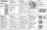
Fieldpiece
Quick Start
1. For electrical testing, connect test leads to
"COM" and "+" jacks. For temperature testing,
remove test leads and slide TEMP switch to
the right.
2. Rotate the dial to your desired function. Press
SEL to cycle through the parameters within
the switch position.
3. Connect to test points and read measurement
on display.
Swivel
Clamp
Meter
OPERATOR'S
MANUAL
NCV
IEC/EN61010-1
IEC/EN61010-2-032
EMC EN61326-1
IN
SEL
MFD
%
Hz
°F°C
O
F
Battery Life (replace
9V if blinking)
F
Display
O Hz
F AAC
F VAC VDC
Auto Power Off Enabled
High Voltage Warning (+30V)
Manual Range (RNG) Mode
Data Hold Mode (Model SC55)
Inrush Amps Mode (Model SC56)
Continuity Test
Diode Test
Frequency Test (hertz)
Resistance Test (ohms)
Capacitance Test (farads)
Duty Cycle Test (percentage)
Micro Unit (10−6, one millionth)
Milli Unit (10−3, one thousandth)
Kilo Unit (103, one thousand)
Mega Unit (106, one million)
NCV
O
F
F
O
F
F
Rotate dial to the function you want to use.
SEL
Press to cycle through parameters
within a dial position.
O
F
F
Press to illuminate backlight for 60 sec
O
F
F
UL 61010-1, Second Edition
O Hz
F AAC
F VAC VDC
Controls
Your SC55 or SC56 is a swivel clamp multimeter
specifically designed for the HVAC/R technician.
The swivel on the SC55/SC56 allows you to
get a good viewing angle on the display while
taking amperage readings through the clamp,
regardless of wire orientation. The SC55 and
SC56 also contain the functions that are most
relevant for an HVAC/R technician.
The unique temperature circuit allows
the SC55/SC56 to get accurate temperature
readings faster when moving from a rooftop to
a freezer. The easily accessible field calibration
O
allows you to calibrate the temperatureFF on your
SC55/SC56 without hassle.
Inrush current (SC56) allows you to get a
reliable measurement of a motor's startup amp
draw. You can use the inrush measurement to
help diagnose a motor before it fails.
The jaw light (SC56) and backlight
(SC56)
make it easier to use in any lighting condition.
True RMS (SC56) helps you take more accurate
voltage readings on variable frequency drives.
Certifications
SC56
Models SC55 SC56
MFD
%
Hz
°F°C
Description
F
F
C-Tick (N22675)
INRUSH
Press to manually select resolution.
HOLD
O
F
F
WEEE
Press to activate Inrush current
capture mode (SC56).
Press to freeze both displays (SC55).
TRUE RMS AUTO OFF
K-TYPE
CATIII 600V, class II and pollution degree 2
indoor use comply with CE, RoHS compliant.
01
02
Safety Information
!
WARNINGS
MFD
Hz
°F°C
Temperature (°F/°C)
%
Plug any K-type thermocouple directly into the meter to measure
temperature. Cold junction is located “inside meter” and allows for
extremely accurate measurements even in rapidly changing ambient
temperatures (going from rooftop to freezer). No adapter is required.
See Temp Calibration section for calibration instructions.
Range: -30°F to 932°F, (-35°C to 500°C) Resolution: 0.1°
Accuracy: ±(1°F) 32°F to 120°F, ±(1°C) 0°C to 49°C
±(1%+2°F) 32°F to 572°F, ±(1%+1°C) 0°C to 300°C
±(2%+6°F) -30°F to 32°F, ±(2%+3°C) -35°C to 0°C
±(2%+6°F) 572°F to 932°F, ±(2%+3°C) 300°C to 500°C
Sensor type: K-type thermocouple
Overload protection: 30 VDC or 30VAC rms
O Hz
F AAC
F VAC VDC
NCV
30V
MAX
K-TYPE
TEMP
Unplug Leads and Slide
TEMP Switch to the Right
MFD
%
Hz
°F°C
Use the non contact voltage (NCV) feature to test if a wire is hot
or not. Always test on a known live source before using. A three
segment graph will show intensity of field (EF) detected. A red LED
blinks when beeping sound is emitted at >24VAC
AC Voltage Detection Range: 24VAC to 600VAC (50-60Hz)
MFD
%
Hz
°F°C
Voltage AC (VAC) (50Hz-500Hz)
Test power lines (120, 220, 480), test 24V going to controls, and
test for transformer failure.
Ranges: 500mV, 5V, 50V, 500V, 600V Resolution: 0.1mV
Accuracy: ±(1.2% + 8) 500mV range (50-60Hz)
±(1.2%+8), 5V, 50V, 500V; ±(1.5% + 8) 600V range
True RMS: model SC56 only Crest factor: ≤ 3
Input impedance: >100MΩ (500mV), 10MΩ (5V),
9.1MΩ (50V-600V)
09
TRUE RMS AUTO OFF
CAT III
600V
O Hz
F AAC
F VAC VDC
NCV
Non Contact Voltage (NCV)
Please operate the instrument following all instructions
of the operator's manual to avoid imparing safety of the
product.
08
05
Functions
Overrange: (OL) or (-OL) is displayed
Measurement rate: 3.3 times per second, nominal
Zero: Automatic
Operating environment: 32°F to 122°F (0°C to 50°C) at <70%
relative humidity
Storage temperature: -4°F to 140°F (-20°C to 60°C), 0 to 80% RH
(with battery removed)
Accuracy: Stated accuracy @ 73°F±9°F (23°C±5°C), <75%RH
Temperature coefficient: 0.1 x (specified accuracy) per °C [0°C to
19°C (32°F to 66°F), 28°C to 50° C(82°F to 122°F)]
APO (Auto Power Off ): Approx. 30 minutes
Power: Single standard 9-volt battery, NEDA 1604, JIS 006P, IEC 6F22
Battery life: 200 hours typical alkaline (SC55); 100 hours typical
alkaline (SC56)
Low battery indication: Battery icon blinks and "LO.bt" is displayed
when the battery voltage drops below the operating level
Dimensions: 258.3mm(H) x 71.2mm(W) x 42.7mm(D)
Weight: Approx. 278g including battery
Overload protection: 600 VDC or 600VAC rms unless otherwise
stated
Test leads: Use the test leads that are supplied with the meter or UL
listed test leads rated CATIII 600V or above.
DISCONNECT AND UNPLUG TEST LEADS before opening case.
TEST NCV FUNCTION ON KNOWN LIVE WIRE before using.
DO NOT APPLY VOLTAGE greater than 30VAC or 60VDC to the
thermocouple or the jacks when the rotary dial is on °F. (Use
only k-type thermocouples)
REMOVE THE THERMOCOUPLE when taking voltage measurements.
DISCONNECT TEST LEADS when measuring temperature.
DO NOT APPLY VOLTAGE TO THE JACKS when the rotary dial is on
microamps. Even low voltages can cause a current overload and
potentially harm the meter.
07
04
Specifi
cations
Display: 5000 count dual display with backlight
transients can damage the meter beyond
repair. Do not use during electrical storms.
• Do not apply more than rated voltages between
input and ground.
• Isolate capacitors from system and discharge
them safely before testing.
All voltage tests: All voltage ranges will
withstand up to 600V. Do not apply more than
600VDC or AC rms.
Symbols used:
Caution, risk of electric shock
! Caution, refer to manual.
Ground
Double insulation
• Never ground yourself when taking electrical
measurements. Do not touch exposed metal
pipes, outlets, fixtures, etc., which might be
at ground potential, while taking measurements. Keep your body isolated from ground
by using dry clothing, rubber shoes, rubber
mats, or any approved insulating material.
• Disconnect the test leads before opening the
case. Inspect the test leads for damage to the
insulation or exposed wire. Replace if suspect.
Keep your fingers behind the finger guards on
the probes while taking measurements.
• When disconnecting from a circuit, disconnect
the“RED”lead first, then the common“BLACK”
lead. Use one handed testing when possible.
Work with others.
• Turn off power to the circuit under test before cutting, unsoldering, or breaking the
circuit.
• Do not measure resistance (ohms) when circuit
is powered. Isolate load by disconnecting
from circuit.
• Disconnect the meter from the circuit before
turning any inductor off, including motors,
transformers, and solenoids. High voltage
06
03
10
O Hz
F AAC
F VAC VDC
NCV
L
SE
TEMP
CAT III
600V
G
RN
30V
MAX
F
F
MFD
%
Hz
°F°C
Voltage DC (VDC)
O Hz
F AAC
F VAC VDC
Select VDC and the range will automatically be selected to give
the best resolution.
Ranges: 500mV, 5V, 50V, 500V, 600V Resolution: 0.1mV
Accuracy: ±(0.5% + 2)
Input impedance: >100MΩ (500mV), 10MΩ (5V),
9.1MΩO(50V-600V)
F
F
NCV
Check Variable Frequency Drives. Check incoming voltages to
ensure they are cycling at 60Hz or desired frequency.
Ranges: 500Hz, 5kHz, 50kHz, 500kHz, 1MHz Resolution: 0.1Hz
Accuracy: ±(0.1% + 5) Sensitivity: 10Hz to 1MHz: >3.5Vrms
MFD
Hz
°F°C
%
O Hz
F AAC
F VAC VDC
NCV
Set to MFD to test motor start and run capacitors. Capacitors
are one of the most failure prone components in a HVAC/R system.
Discharge capacitor and disconnect from power and resistors
between terminals before testing. If dIS.C is displayed, discharge the
capacitor.
Ranges: 5μF, 50μF, 500μF, 5mF Resolution: 1nF
Accuracy: ±(3% + 15) 5μF, ±(3% + 5) 50μF to 500μF,
±(5% + 20) 5mF
Overload Protection: 600VDC or 600VAC rms
MFD
Hz
°F°C
%
NCV
Your new Swivel Clamp Meter is compatible
with all Fieldpiece Accessory Heads. With
Fieldpiece Accessory Heads, you can measure
any available parameter, and read the
measurement on your new meter's display in
real-time.
Just set the range to VDC and press the
RANGE button until mV is displayed. Remove
the probe tips of your test leads, and connect
your accessory head (model AAV3 shown).
ON
LCD X
100
LO BATT
READ
Metric
Real
time
English
Metric
Ft/min
MPH
ºF
M/s
KM/hr
ºC
OFF
AUTOOFF
AAV3
RNG
Test diodes for proper forward and reversed-biased functions.
Turn dial to Ω position and press SEL button twice.
Test current: 0.8mA (Approx.) Accuracy: ±(1.5% + 5)
Overload Protection: 600VDC/VACrms
13
O Hz
F AAC
F VAC VDC
NCV
MFD
Hz
°F°C
%
SEL
Visit www.fieldpiece.com to see all of the
different accessory heads that Fieldpiece
offers.
17
NCV
Inrush Current (SC56 only)
O Hz
F AAC
F VAC VDC
Inrush feature captures current at start of first 100ms period
of a motor start. This can help diagnose a motor before it fails.
To activate Inrush, turn dial to VAC/AAC/Hz position, press SEL to
show AAC on top display, then press the INRUSH button on the
side of the meter once for 50AAC range and twice for 400AAC.
Inrush measurement period: 100-milliseconds
Minimum input: >2A on 50A range; >20A on 400A range
NCV
14
O Hz
F AAC
F VAC VDC
15
Temp. Calibration
Safety Features
Maintenance
Obtaining Service
For accuracies of ±1°F,
calibrate to a known
temperature. A glass
of stabilized ice water
is very close to 32°F
(0°C) and is usually very
convenient but any
known temperature can
be used.
1. Bright LED and beeper warn you when testing
voltages above 30V.
2. Switch to the NCV function (non contact voltage) and point clamp claw towards suspected
voltage source. Monitor the bright LED and
beeper to see if the source is “hot.”
3. Rotate the clamp to the angle that best suits
the situation.
4. Temp switch to prevent leaving thermocouple
plugged in while measuring voltage.
5. LED flashlight automatically shines when
clamp jaw is opened (model SC56 only).
Clean the exterior with a dry cloth. Do not
use liquid.
Call Fieldpiece Instruments for one-price-fixall out-of-warranty service pricing. Send check
or money order for the amount quoted. Send the
meter freight prepaid to Fieldpiece Instruments.
Send proof of date and location of purchase for
in-warranty service. The meter will be repaired
or replaced, at the option of Fieldpiece, and
returned via least cost transportation.
1. Select the 400°F range.
2. Plug thermocouple to be
calibrated into the K-type jack.
3. Unscrew A and B and remove
the battery cover.
4. Stabilize a large cup of ice
water. Stir the ice with the
water until temperature stays
at 32°F (0°C)
5. Immerse the thermocouple
probe and let it stabilize. Keep
stirring to prevent microenvironments.
6. Use a small screwdriver to
adjust calibration pot C to the
right of the battery as close to
32°F as you would like.
Air Velocity
& Temperature Average
English (16 sec)
Head
MFD
Hz
°F°C
%
Diode Test ( )
Discharge Cap First!
Modular
Expandability
16
O Hz
F AAC
F VAC VDC
12
NCV
MFD
Hz
°F°C
%
Use the continuity feature to test if a circuit is open or closed.
Use this feature to check fuses as well. A steady “beep” and green
LED indicate the circuit is good. Turn dial to Ω position and press SEL
button once.
Range: 500Ω Resolution: 0.1Ω Response time: 100ms
Audible beep: <30Ω Overload Protection: 600VDC/VACrms
Capacitance (MFD)
MFD
Hz
°F°C
Measure frequency without using test leads, just use the clamp.
Turn dial to VAC/AAC/Hz and press SEL twice. Clamp Hz upper display.
Range: 10Hz to 400Hz Accuracy: ±(0.1% + 5)
Minimum current range: > 5AAC Overload Protection: 400AAC
Resolution: 0.1Hz
Continuity ( )
Duty cycle shows the % of the AC waveform which has postitive
amplitude. Ranges: 5%-95% (40Hz to 20kHz) PW: >10μs
Resolution: 0.1% Accuracy (5V logic): ±(2% + 10)
%
NCV
Frequency (Hz) through Clamp
Used for “ohming out” a motor. 0.1Ω resolution is necessary to
test the resistance between the motor poles because the values are
typically very low.
Ranges: 500Ω, 5kΩ, 50kΩ, 500kΩ, 5MΩ, 50MΩ
Resolution: 0.1Ω Overload Protection: 600VDC/VAC rms
Accuracy: ±(1.0% + 5) 500Ω to 500kΩ, ±(1.5% + 5) 5MΩ, ±(3.0%
+ 5) 50MΩ
Duty Cycle (%)
O Hz
F AAC
F VAC VDC
Test any isolated power line. Press SEL on VAC/AAC/Hz position.
AAC will display in the upper display. True RMS on model SC56 only.
Ranges: 50A, 400A Resolution: 0.01A Crest factor: ≤ 3
Accuracy: ±(2.0% + 10) 50-60Hz Jaw Opening: 1.2in (30 mm)
Resistance (Ω)
Frequency (Hz) through Leads
11
MFD
%
Hz
°F°C
Amps AC (AAC)
O Hz
F AAC
F VAC VDC
L
SE
Microamps for flame rectifier diode test on a heater control.
Connect leads between flame sensor probe and control module and
turn heating unit on to read μA measurement. When the flame is on,
there should be a measurable μADC signal, typically under 10μADC.
Compare measurement to manufacture’s specification to determine
if replacement is necessary.
Ranges: 500μA Resolution: 0.1μA
Accuracy: ±(1.0% + 2) Voltage burden: 1V
Overload Protection: 600VDC or 600VAC rms
G
RN
MicroAmps DC (μADC)
A
Limited Warranty
This meter is warranted against defects in
material or workmanship for one year from
date of purchase. Fieldpiece will replace or
repair the defective unit, at its option, subject
to verification of the defect.
This warranty does not apply to defects
resulting from abuse, neglect, accident,
unauthorized repair, alteration, or unreasonable
use of the instrument.
Any implied warranties arising from the sale of
a Fieldpiece product, including but not limited
to implied warranties of merchantability and
fitness for a particular purpose, are limited to
the above. Fieldpiece shall not be liable for loss
of use of the instrument or other incidental or
consequential damages, expenses, or economic
loss, or for any claim of such damage, expenses,
or economic loss.
State laws vary. The above limitations or
exclusions may not apply to you.
Battery Replacement
C
The battery must be replaced when the
battery icon is empty and blinking. The icon
will blink for 30 seconds, then the meter will
display LO.bt and further measurement will not
be allowed until battery is replaced. Disconnect
and unplug leads, turn meter off and remove
battery cover. Replace the battery with a
standard NEDA type 1604 9V battery.
18
19
www.fieldpiece.com
© Fieldpiece Instruments, Inc 2010; v21
20