1
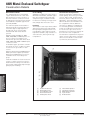
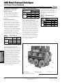
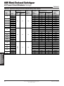
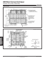
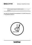
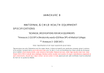
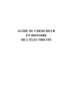
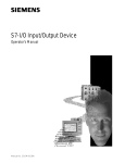
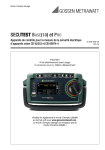
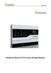
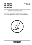
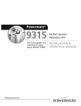
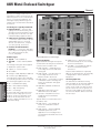
480V Metal-Enclosed Switchgear
General
Siemens low-voltage metal-enclosed
switchgear is used in electric power distribution systems for the control and protection of circuits and equipment. The
switchgear employs drawout type low
voltage power circuit breakers described
in Section 4.
LV switchgear is typically installed in:
쐍 Industrial Plants — for power and
lighting networks and feeders, power
generation and other auxiliaries, and to
provide power for machine tools and
material handling equipment drivers.
쐍 Utility and Co-generation Facilities
— for motor control centers to protect
and distribute power to electrical
devices such as blowers, compressors, fans, pumps, and motors.
쐍 Commercial and Residential
Buildings — for protection and distribution of power for lighting, elevators,
air conditioning, blowers, fans,
motors, and pumps.
480V Metal-Enclosed
Switchgear
4
Available Types:
쐍 Type R — indoor (NEMA 1)
쐍 Type SR — outdoor walk-in (NEMA
3R)
Low-voltage switchgear can be applied
on distribution systems with:
쐍 3-phase, 3- or 4-wire feeders
쐍 50 or 60Hz
쐍 Voltages of 208, 240,480, or 600 volts
쐍 Currents up to 5000 amperes
Circuit breakers may be either manually
or electrically operated, fused or unfused.
The following designations are used:
쐍 RL — Standard Interrupting
쐍 RLE — Extended Interrupting
쐍 RLI — High Interrupting
쐍 RLF — Fused Type
Siemens Static Trip III trip units are provided on all low voltage power circuit
breakers, except non-automatic circuit
breakers. All circuit breakers are UL
Listed. See Tables 4.10 and 4.11 for circuit breaker ratings.
50
480 Volt Metal-Enclosed Switchgear
Industry Standards
Types R and SR switchgear with power
circuit breakers are designed, tested and
constructed in accordance with:
쐍 ANSI C37.20.1 — Metal-Enclosed
Low Voltage Power Circuit Breaker
Switchgear
쐍 ANSI C37.50 — Test Procedure for
Low Voltage AC Power Circuit
Breakers Used in Enclosures
쐍 ANSI C37.51 — Conformance Testing
of Metal-Enclosed Low Voltage AC
Power Circuit Breaker Switchgear
Assemblies
쐍 Applicable standards of IEEE and
NEMA
쐍 Applicable requirements of the
National Electric Code (NEC)
쐍 UL 1558 — Metal-Enclosed Low
Voltage Power Circuit Breaker
Switchgear
Type RL drawout circuit breakers are in
accordance with:
쐍 ANSI C37.13 — Low Voltage AC
Power Circuit Breakers Used in
Enclosures
쐍 ANSI C37.16 — Preferred Ratings,
Related Requirements, and
Application for Low Voltage Power
Circuit Breakers and ACPower Circuit
Protectors.
Siemens Electrical Products and Systems
Specification Guide
쐍 ANSI C37.17 — Trip Devices for AC
and General Purpose DC Low- Voltage
Power Circuit Breakers.
쐍 UL 1066 — Low Voltage AC and DC
Power Circuit Breakers Used in
Enclosures.
Features and modifications required by
NEC are incorporated when the assembly
is designated as “Service (Entrance)
Equipment.”
UL Listing (Optional)
An Underwriters’ Laboratories listing
mark (UL label) can be optionally supplied
for each vertical section. The specific
section must contain only devices which
are UL Listed or are UL recognized components found suitable for the intended
use. All circuit breaker drawout elements
are UL Listed.
CSI Section 16470
480V Metal-Enclosed Switchgear
Construction Details
General
The Siemens 480 volt switchgear assembly consists of one or more metalenclosed, vertical sections. Normally the
end sections are designed to allow for
installation of future sections.
Each vertical section consists of up to
four individually enclosed breaker or auxiliary compartments which are sized to
provide uniform height.
Included in each assembly are various
components such as circuit breakers,
instrumentation and control equipment,
transformers, relays, three-phase bus
work, and all internal wiring, connectors,
and other supporting equipment.
In accordance with ANSI C37.20.1, the
maximum temperature for parts that are
handled is 50°C. The main bus maximum
temperature rise is 65°C above 40°C
ambient. The temperature rise of the air
surrounding the cable connection points
is limited to 45°C above 40°C ambient.
General
Finish
During construction, the structural steel
parts, panels, and compartments are all
prepared for painting by a five-stage
wash system. Standard finish color is
light gray ANSI 61. If a different finish
color is required, it is applied over the
standard finish with conventional spray
equipment and is allowed to air cure. The
completed finish has a nominal 2 mils dry
film thickness.
Assembly Construction
Siemens metal-enclosed power
switchgear is constructed of preformed,
full-depth, 14-gauge steel sheets bolted
together and reinforced with cross-member braces to form a rigid, self-supporting
compact assembly. The top and rear
plates, and side sheets are all 14-gauge
steel. When two vertical sections are
mounted together, two sheets of 14gauge steel separate adjacent circuit
breaker compartments.
Bolted steel / glass polyester compartments housing each power circuit breaker are mounted in the vertical section to
form the switchgear assembly. This isolates the circuit breakers from the bus /
cable section and from adjacent circuit
breaker compartments.
The bus / cable section includes main
horizontal bus, riser bus, connections
from the main bus to each set of primary
disconnects, and load side copper runback bus.
Grounded metal barriers can be provided
to isolate the main bus from cable connections. Barriers are also available to
isolate the incoming line to the main circuit breakers from the main load bus of
the switchgear.
햴
햳
햲
4
480V Metal-Enclosed
Switchgear
햵
햶
햲 Inter-Unit Wiring Trough
햳 Meter and Auxiliary Compartment
햴 Ventilation and Lifting Structure
햵 Telescoping Breaker Drawout Rails
햶 Ventilation Openings (RL-2000, RL-3200, RL-4000
and RL-5000)
CSI Section 16470
Siemens Electrical Products and Systems
Specification Guide
51
480V Metal-Enclosed Switchgear
Construction Details
Main and Ground Bus
The standard main bus is silver-plated
copper. Welded aluminum is also available. Provisions for future extension of
aluminum main bus conductors include
tin plated joints with high tensile strength
steel hardware. Tin-plated copper bus is
optionally available.
The main three-phase horizontal bus is
arranged vertically one phase above the
other with edge-to-edge alignment to
provide high, short circuit strength.
Insulated main and vertical bus are
optional.
Main bus ratings available are 1600,
2000, 3200, 4000, or 5000 amperes continuous current. A neutral bus is furnished when specified, and can be rated
1600, 2000, 3200, 4000 or 5000 amperes
continuous current.
A standard copper ground bus extends
through all sections. A cable lug can be
mounted to the ground bus in each
section.
Minimum bus bracing is 65,000 amperes
RMS symmetrical. Higher symmetrical
bracings are available based on the lowest breaker short circuit rating in the
group.
Load side runbacks for feeder circuits are
one-piece copper construction, are insulated with sleeve tubing in the main bus
area, and are supported by high-strength,
glass polyester moldings.
General
Control Wiring
Standard secondary and control wiring is
#14 AWG extra-flexible, stranded copper
type SIS. Terminations are made with
compression-type, insulated terminals.
For devices not having screw-type terminals, tab-type disconnects are used.
Insulation
The insulation used is Pyro-Shield, a fiberglass-reinforced polyester material that
has high impact strength and low moisture absorption. Other features include
high flame retardance, high resistance to
chemical fumes, and long life at high
temperatures.
Circuit Breaker Compartments
Typical circuit breaker compartments
include primary disconnects, ground disconnect, drawout rails, and associated
interlocks, and secondary disconnects, if
appropriate. Telescoping drawout rails
allow the breaker to be withdrawn from
the compartment without additional
extensions or adapters. Compartments
for electrically-operated circuit breakers
include secondary disconnects and control circuit fuses. Up to three current
transformers for metering or relaying can
be mounted in each compartment.
Circuit breaker compartment front panels
can be used to hold a variety of auxiliary
devices such as breaker control switches, ammeters, and test blocks.
480V Metal-Enclosed
Switchgear
4
햲
햳
햴
햵
햶
Control Circuit Fuses
Ground Disconnect
Secondary Disconnect
Front Panel Devices
Primary Disconnect
햷
햸
햹
햺
햻
TOC Switch Operator
Interference Interlock
MOC Switch Operator
Space Heater
Drawout Rails
Circuit Breaker Cell Interior
52
Siemens Electrical Products and Systems
Specification Guide
CSI Section 16470
480V Metal-Enclosed Switchgear
Guide Form Specifications
General
Options
Switchgear Mounted Hoist
The hoist, optional on type R indoor
switchgear, and standard on type SR
outdoor switchgear, travels along rails on
top of the switchgear to ease breaker
handling.
TOC and MOC Switches
The Truck Operated Cell (TOC) Switch
provides interlocking control or remote
indication of the breaker racking position.
The cubicle mounted auxiliary switch or
Mechanism Operated Cell (MOC) switch
provides interlocking control or remote
indication based on the main contact
position (open or closed).
The switches have field adjustable contacts for simple conversion of contacts
from normally open (“a” type) to normally closed (“b” type). Each contact may be
adjusted individually without disassembly
or removal of wiring.
Typical Outdoor Installation with Liquid Filled Transformer
PTS4 Test Set
Set allows testing of the full range of protective settings of Static Trip III trip units.
Metering and Auxiliary Compartments
Compartments are available to house
devices such as voltage transformers,
metering, control power transformers,
and supervisory devices.
Shutters
These provide protection against accidental contact with primary disconnects in a
compartment when the breaker is
removed.
Wire Trough Covers
Secondary wiring is enclosed within each
vertical section in the primary bus and
outgoing cable areas.
Key Interlock
This provides a mechanical means for
operating circuit breakers and other
devices only when predescribed conditions are met.
CSI Section 16470
Outdoor Switchgear
Type SR outdoor switchgear, available up
to 4000 amp, is enclosed in a weather
resistant (NEMA 3R) steel housing. All
exterior doors extend below the floor line
and are gasket sealed.
For protection from snow, rain, and dust,
the switchgear rests on a six-inch,
formed steel base which provides rigid
support and a tight bottom seal. A heavy
duty, coal tar emulsion protective undercoating is applied to the underside for
protection against moisture and corrosion. Shielded ventilation housings permit
proper air circulation while excluding
dust, dirt, and foreign matter.
Accessories
Each switchgear assembly includes the
following standard accessories:
쐍 Crank for circuit breaker racking
쐍 Lifting bar assembly for all circuit
breaker types
쐍 Spring charging handle for electrically
operated circuit breakers
As an optional accessory, a test cabinet
is available for indoor use that is wall
mounted with necessary equipment for
testing electrically-operated breakers that
have been removed from the breaker
compartments.
Portable PTS4 Test Set
Siemens Electrical Products and Systems
Specification Guide
53
4
480V Metal-Enclosed
Switchgear
MOC and TOC Switches. TOC Shown
with Cover Removed.
Instrument and Control Transformers
Voltage transformers and control power
transformers are mounted in auxiliary
compartments. These transformers are
protected by primary pull-out type current-limiting fuses and secondary fuses.
Current transformers are normally mounted on the compartment primary disconnect studs where they are readily accessible. See Tables 4.10, 4.11, 4.12, and
4.13 for available ratings.
A lighted, unobstructed service aisle is
provided at the front of the switchgear
allowing inspection and maintenance
without exposure to the elements, An
access door equipped with an emergency bar release is located at each end
of the aisle. A GFI convenience outlet is
included.
480V Metal-Enclosed Switchgear
LV Power Circuit Breakers
General
The Siemens RL series circuit breakers
are designed for up to 600 volt service
with current carrying capacities of up to
5000 amperes and interrupting capacities
of up to 130,000 amperes unfused or
200,000 amperes fused.
These compact, fast operating circuit
breakers incorporate a stored energy
closing mechanism, either manually or
electrically charged, for fast, positive
closing.
A quick-make closing mechanism releases the stored energy for high speed closing of the primary contacts. This positive,
controlled closing prevents unnecessary
arcing between the movable and stationary breaker contacts and thus lengthens
contact and breaker life.
Manual tripping is performed with the
push lever on the front of the breaker. Up
to three padlocks can be used to lock the
breaker contacts in the open position.
480V Metal-Enclosed
Switchgear
4
Typical Breaker Features
쐍 Arc Quenchers
쐍 Main and Arcing Contact Structures
쐍 Inductive Tripping Sensors
쐍 Control Wiring
쐍 Interlocks
쐍 Position Indicators
쐍 Interpole Barriers
쐍 Mechanical Trip Bar
쐍 Auxiliary Switches (option)
Each circuit breaker is a complete 3-pole,
single-throw element that is mechanically
and electrically trip-free, with a Static Trip
III overcurrent trip unit.
Tables 4.16 and 4.17 show circuit breaker
operating and control data.
Circuit Breaker Racking
Racking is accomplished by turning a
racking screw on the front of the breaker
and may be done with the compartment
door open or closed. The racking screw
turns U-shaped brackets on each side of
the breaker which rack the breaker frame
in or out of the compartment.
As the racking screw is turned counterclockwise, the breaker frame moves out
of the compartment and disconnects the
primary contacts, followed by the secondary contacts. With only the secondary
contacts connected (test position), the
breaker may be closed and opened for
testing without energizing the load. An
indicator located on the front of the
breaker identifies the position of the
breaker in the compartment.
54
Type RL Circuit Breaker With Static Trip III Trip Unit And Optional Breaker Display Unit (BDU)
Primary Disconnects
Primary current is applied to the circuit
breaker through silver plated disconnects.
The stationary contacts are mounted
through solid Pyro-Shield insulation
sheets in the back of the compartments.
The movable contacts are mounted on
the back of the breaker. Stainless steel
springs provide pressure to the finger
contacts in the connected position. Low
contact resistance is maintained by these
self-aligning contacts. The primary contacts are positioned so that current can
flow only in the connected position. In
the test position the contacts are separated a safe distance.
Secondary Disconnects
Secondary circuits are connected to the
circuit breaker through silver-plated, slidetype contacts which are located below
the arc quenching area to avoid contamination from arc product gases. The position of these contacts is visible with the
panel door open. The stationary contacts
are silver-plated copper strips mounted
on a Pyro-Shield molded base. The contacts are recessed to guide the movable,
self-aligning contacts and to prevent accidental short circuiting. Secondary connections are made automatically in both the
connected and test positions.
Siemens Electrical Products and Systems
Specification Guide
Secondary Disconnects in Cell
Left = Communications
Right = Breaker Control
Main and Arcing Contacts — Similar
Design for all Ratings
CSI Section 16470
480V Metal-Enclosed Switchgear
LV Power Circuit Breakers
General
Ground Connection
A ground contact is located on the circuit
breaker to connect with the ground circuit. The breaker is grounded in both the
connected and test positions.
Drawout Interlocks
All circuit breakers have drawout interlocks to:
쐍 prevent racking a closed breaker
쐍 prevent closing breaker until racked to
connected or test position
쐍 prevent inserting or withdrawing
breaker from compartment while closing springs are charged
Arc Interruption
When a fault occurs, the main contacts
open first, transferring the fault current to
the arcing contacts. As the arcing contacts open, the thermal and electromagnetic characteristics force the arc into the
arc chute, where the metal plates lengthen, constrict, and cool the arc.
Current Limiting Fuses
The 800,1600 and 2000 ampere circuit
breakers are available with integrally
mounted current limiting fuses to
increase interrupting rating and / or to
limit short circuit (let-through) current.
The fuses are bolted in series with the
upper set of primary disconnects. The
breakers meet all required standards and
are UL Listed based on current limiting
fuses.
An open fuse tripping device is wired in
parallel with the main fuses to insure that
the circuit breaker opens if a main fuse
interrupts, thus preventing single phasing.
This device holds the circuit breaker tripfree until it is reset and also indicates
which main fuse has interrupted.
햲
햳
햴
햵
햶
햷
햸
햹
햺
햾
햿
헀
헁
헂
헃
헄
헅
헆
Clevis attached to racking drive
screw.
Circuit breaker rating nameplate
Racking interlock bar
Static Trip III trip unit test points
Static Trip III overcurrent device
Tripping lever (with padlocking
provisions) with guard.
Breaker Display Unit (optional)
Power switch for spring charging
motor (electrically operating breaker only)
Spring charging motor (electrically
operated breaker only)
Auxiliary switch (optional on manually operated breakers)
RL Circuit Breaker Features (Electrically Operated Breaker Shown)
open position. The carriage mounts in the
same vertical section as the circuit breaker element.
Integrally Fused RLF-800 Circuit Breaker
The higher raed circuit breakers, 3200,
4000 and 5000 ampere, are available
with current limiting fuses mounted on a
separate drawout carriage, which is key
interlocked with the circuit breaker. This
allows racking of the fuse carriage with
only the associated circuit breaker in the
CSI Section 16470
Current Sensors
The tripping system of the RL breaker is
self-powered from the current sensors
mounted on the primary contacts of the
breaker element (four-wire ground applications include a fourth sensor mounted in
the cable compartment). A signal from the
current sensors, proportional to primary
current, is applied to the trip device which
then operates the actuator to trip the
breaker based on a pre-set time delay
versus current magnitude relationship.
Siemens Electrical Products and Systems
Specification Guide
Table 4.1
Available Sensor Ratings 햲
Frame Size and
Max Amp Rating
Sensor Ratings
800
150, 200, 300,
400, 600, 800
1600
150, 200, 300, 400,
600, 800, 1200, 1600
2000
150, 200, 300, 400,
600, 800, 1200, 1600, 2000
3200
1200, 1600, 2000, 3200 햲
4000
1600, 2000,
3200 햲, 4000 햲
5000
5000 햲
햲 Optionally
available with integral 200A ground sensor
winding to meet NEC 239-95 requirements.
55
4
480V Metal-Enclosed
Switchgear
햻
햽
Ground shoe contact
Mounting rails
Racking position detent
Stored energy mechanism position
indicator
Contact position indicator
Arc chutes
Handle for manually charging stored
energy closing springs (optional on
electrically operated breakers)
Inter-phase barriers
Racking mechanism shutter (with
packlocking provisions)
Racking position indicator
Contact closing release lever
(behind charging handle)
480V Metal-Enclosed Switchgear
LV Power Circuit Breaker Trip Unit
General
Static Trip® III Trip Unit
Static overcurrent tripping devices have
been standard on Siemens circuit breakers for over thirty years. The Static Trip Ill
trip unit features microprocessor-controlled tripping, while providing RMS
sensing for standard overcurrent protection, and optional metering and communications functions. Located in the lower
right side of the breaker, the trip unit is
readily accessible for simple reading and
adjustment of all settings and indicators.
Static Trip III trip units are interchangeable on all ratings of low voltage circuit
breakers.
The time / current characteristics of the
Static Trip III trip unit are shown on page
62.
All communicating Static
Trip III trip units include
a local communication
port that supports the
breaker-mounted display
unit or BDU. The BDU
features a high-visibility
alpha-numeric display. Real-time metered
values, min/max values, event log data
and setpoint data can be read on the
BDU in straightforward engineering units.
Alarm and relay setpoint can be configured using the BDU keypad.
This data can also be communicated to
other devices or computers for control
monitoring via Siemens’ ACCESS system. See Section 1 of this guide for a
thorough description of ACCESS.
Table 4.2
Static Trip III Settings
T: Long Time
Siemens RMS sensing samples the entire
current wave shape and calculates the
effective heating value of the current.
Static Trip Ill trip units provide accurate
protection and avoid unnecessary trips.
4
480V Metal-Enclosed
Switchgear
Static Trip® Ill Trip Unit (right) and Breaker Display Unit (left)
Setting 햲
(X Sensor Rating)
Delay
(Seconds @ 6X Setting)
.5, .55, .6, .65, .7, .75,
.8, .85, .9, .95, 1.0
S: Short Time
3.5, 6, 10
17, 30
Pickup
(X LT Setting)
Delay
(Seconds)
2, 3, 4, 5,
6, 7, 8, 12
I: Instantaneous
0.8, .15, .22
.30, .40
Pickup
(X Sensor Rating)
Delay
(Seconds)
2, 4, 6, 8,
12, 15
G: Ground Fault
No Intentional
Delay
Pickup
(% Ground Sensor)
20, 30, 40, 50, 60
Delay
(Seconds)
.10, .25, .40
햲
Pickup is fixed at 1.1 times long time setting.
Harmonics distort the current wave shape
and can increase its peak value. Normal
peak-sensing units may trip, causing nuisance shutdowns.
56
Siemens Electrical Products and Systems
Specification Guide
CSI Section 16470
480V Metal-Enclosed Switchgear
LV Power Circuit Breaker Trip Unit
Table 4.3
Static Trip III Trip Unit Functions
Function
Self-Powered Overcurrent Protection
RMS Sensing
Switchable Thermal Memory
Ground Fault Protection
LCD Target
Protective Microprocessor Watchdog
Pickup LEDs
Zone Interlocking 햲 (For Short Time and Ground Fault)
Retrofit Universal Mounting Package
RS-485 Communications Port
Breaker Display Unit Port 햳
Communications Microprocessor Watchdog
Comm Watch LED
Backup Shadow Protection
Trip Log
Alarm Relay Output 햲
Trip Unit Status Indication
Breaker Position Indication
Breaker Operation Counter
Communication Open/Close/Trip 햲 햴
Event Log
Phase Current Metering
Ground Current Metering 햵
Neutral Current Metering 햶
Min/Max Current Log
Power Metering Functions
Min/Max Power Log
Extended Protective Relaying
Extended Trip Log
Table 4.4
General
Model
III
Table 4.5 Static Trip III Metering
Functions
IIIC
IIICP
IIICPX
✓
✓
✓
✓
✓
✓
✓
✓
✓
✓
✓
✓
opt
opt
opt
opt
✓
✓
✓
✓
✓
✓
✓
✓
✓
✓
✓
✓
opt
opt
—
—
—
—
—
—
—
—
—
—
—
—
—
—
—
—
—
—
—
—
opt
opt
opt
opt
opt
opt
✓
✓
✓
✓
✓
✓
✓
✓
✓
✓
✓
✓
✓
✓
✓
✓
✓
✓
opt
opt
opt
✓
✓
✓
✓
✓
✓
✓
✓
✓
opt
opt
opt
✓
✓
✓
✓
✓
✓
✓
✓
✓
opt
opt
opt
✓
✓
✓
✓
✓
✓
✓
✓
✓
—
—
—
—
—
—
Function
Phase Currents
Avg Phase Currents
Ground Current 햵
Neutral Current 햶
Phase Voltage 햷
Avg Phase Voltage 햷
Line Voltages
Avg Line Voltages
kW
kW Demand
kW Hours
kW Hours Reverse
kVA
kVAR
kVAR Hours
Power Factor
Frequency
Model
IIIC
IIICP
✓
✓
✓
✓
✓
✓
opt
—
—
—
—
—
—
—
—
—
—
—
—
—
opt
✓
✓
✓
✓
✓
✓
✓
✓
✓
✓
✓
✓
✓
햲 Requires
additional compartment mounted devices
and wiring to meet specific application.
햳 Supports optional Breaker Display Unit accessory.
햴 Open command uses alarm relay output and restricts
use for other alarm functions. Close command
requires electrically operated breaker.
햵 Included when ground fault protection specified.
햶 Requires “N” option and neutral current sensor.
햷 Only displayed for four wire systems.
Static Trip IIICPX Protective Relay Functions
Setting
Range
5–50%
5–50%
60–660V
60–660V
10–2000kW
50.0–70.0 Hz
45.0–60.0 Hz
RL Breaker
Accessories/Modifications
Type RL circuit breakers feature several
options, including:
쐍 Shunt Trip, (for MO breakers)
쐍 Operation Counter
쐍 Undervoltage Trip Device
쐍 Electrically Operated Interlock
쐍 Automatic Trip Alarm Contact (with or
without Lockout Bell Alarm)
CSI Section 16470
Typical Applications
Motors
Generators
✓
✓
—
✓
—
—
—
✓
Mains
—
—
✓
✓
✓
✓
✓
✓
—
—
✓
4
—
—
Tripping Actuator
The tripping actuator is a low energy,
flux-shifting device that allows fast action
tripping of the breaker.
Shunt Trip
The shunt trip is used to electrically trip
the circuit breaker from a remote device,
such as pushbutton, switch, or relay. The
shunt trip is standard on all electrically
operated breakers, optional on manually
operated breakers. The shunt trip coil is
designed for a momentary duty cycle.
Thus, an “a” type auxiliary contact switch
is used to interrupt the shunt trip circuit
immediately after the breaker is tripped.
Siemens Electrical Products and Systems
Specification Guide
Table 4.6
Shunt Trip Coil Ratings
Nominal Control
Voltage
120
60 Hz
AC
240
48
125
DC
250
Operating
Voltage
Range
104–127
208–254
28–56
70–140
140–280
Shunt Trip
(Amperes)
Seal-In/Inrush
1.65/7.7
0.71/3.4
5.45
2.76
1.85
When the coil is energized, the armature
picks up and rotates the trip latch, thereby tripping the breaker. A compression
spring returns the armature to the normal
position.
57
480V Metal-Enclosed
Switchgear
Protective Function
Current Unbalance
Voltage Unbalance
Overvoltage
Undervoltage
Reverse Power
Overfrequency
Underfrequency
480V Metal-Enclosed Switchgear
LV Power Circuit Breakers
RL Breaker Accessories /
Modifications (cont’d)
Table 4.8
Operation Counter
A mechanically-operated, 5-digit nonresetable counter can be mounted
beneath the breaker auxiliary switch.
The counter is incremented by the
action of the auxiliary switch operating
mechanism.
Undervoltage Trip Device
The undervoltage trip device protects
against a drop in normal bus voltage and
functions to directly trip the breaker.
Pickup occurs at 85 percent or less of
rated value and dropout between 30 and
60 percent of rated value. Pickup and
dropout are individually adjustable.
Instantaneous or time-delayed operation
can be provided. The static timing unit is
adjustable from 0.04 to 4 seconds for
time delay. This allows the system to
distinguish between undervoltage
conditions and momentary voltage dips.
Table 4.7
Ratings
Undervoltage Trip
Nominal Control
Voltage
120
60 Hz AC
240 or
480햲
48
DC
125
Pickup
Voltage
100
Dropout
Voltage
60
—
—
40
105
24
62
General
Interlock Coil Ratings
Nominal Control
Voltage
120
60 Hz AC
240
48
125
DC
250
Voltage Range
Pickup
Dropout
Voltage
Voltage
104
36
208
72
38
15
100
38
200
75
Automatic Trip Alarm Contact (with or
without Lockout) (Bell Alarm)
The bell alarm contact is operated when
the trip actuator operates in response to
the Static Trip III trip unit. It indicates
when the circuit breaker has tripped as a
result of the static trip unit. The contact
can control a local or remote auxiliary
alarm for indication of an automatic trip
or, by wiring in series with a breaker closing coil, for interlocking to prevent circuit
breaker closure until the circuit is reset.
The contact must be reset manually or
electrically (optional). The manually reset
switch is available with a single-pole
double-throw contact, or two single-pole
single-throw contacts. The electrically
reset switch is available with a singlepole single-throw contact.
If desired, a mechanical lockout option
may be provided. This substitutes a
manual reset for the automatically reset
tripping actuator. In this case the breaker
is held trip free until the lockout is
manually reset.
Table 4.9
Ratings
Nominal
Control
Voltage
60 Hz
AC
DC
120
240
48
125
250
Bell Alarm Contact
Bell Alarm Contact Ratings
(Amperes)
Continuous
Make
Break
10.0
10.0
10.0
10.0
10.0
10.0
10.0
0.5
0.5
10.0
0.5
0.5
10.0
0.25
0.25
햲 Not
available. Use 120 VAC undervoltage device with
appropriate 240/120V or voltage transformer in cubicle.
480V Metal-Enclosed
Switchgear
4
Electrically Operated Interlock
This can be added to interlock two breakers, preventing both from being closed at
the same time. These electromechanical
devices add an additional solenoid that
must be energized before the breaker
can be closed. When the interlock is deenergized, the breaker is held trip-free
and cannot be closed electrically or
manually. The interlock has a mechanical
link that goes to the main shaft of the
breaker. The interlock is held in the
picked-up position when the breaker is
closed. Once closed the interlock can be
de-energized without tripping the breaker.
There are no adjustments for pickup or
dropout voltages. The interlocks are
continuously energized.
� Current Sensors
� PT Module (Optional)
� Ground Shoe Contact
� Primary Disconnects
� Secondary Disconnects
RL Circuit Breaker – Rear View
58
Siemens Electrical Products and Systems
Specification Guide
CSI Section 16470
480V Metal-Enclosed Switchgear
VT, CPT, CT Data
Table 4.10
Technical
Voltage Transformers
Accuracy Class at 60 Hz
Burden
Thermal
Rating
VA
Hertz
Ratio
W
X
Y
Volt-Amp
Rating
600:120
0.6
0.6
1.2
100
150
50/60
480:120
0.6
0.6
1.2
100
150
50/60
288:120
0.6
0.6
1.2
100
150
50/60
Table 4.11
햲 Requires
Control Power Transformers—115°C Rise
kVA
Phase
Primary
Voltage
Secondary
Voltage
3
5
10 햲
15 햲
Single
240/480
120/240
complete compartment.
Table 4.12
Current Transformers for RL-800, RLE-800, RLI-800, RL-1600, RLE-1600, RL-2000, or RLE-2000 Applications햳
Accuracy at 60 Hz Metering Burden (ohms)
햳 Breaker
B-1.0
B-2.0
B-0.1
B-0.2
B-0.5
100:5
1.2
2.4
—
—
—
C5
150:5
1.2
2.4
—
—
—
C5
200:5
1.2
1.2
—
—
—
C10
250:5
0.6
1.2
—
—
—
C10
300:5
0.6
0.6
1.2
—
—
C10
400:5
0.6
0.6
1.2
—
—
C5
500:5
0.6
0.6
0.6
—
—
C10
600:5
0.3
0.6
0.6
1.2
—
C10
800:5
0.3
0.3
0.6
0.6
—
C15
1000:5
0.3
0.3
0.3
0.6
1.2
C20
1200:5
0.3
0.3
0.3
0.6
1.2
C20
1500:5
0.3
0.3
0.3
0.3
0.6
C30
1600:5
0.3
0.3
0.3
0.3
0.6
C30
2000:5
0.3
0.3
0.3
0.3
0.6
C5
2500:5
0.3
0.3
0.3
0.3
0.3
C10
compartment will accept 3 CT’s in-line on lower disconnects.
Table 4.13
Current Transformers for RL-3200햴, RLE-3200햴, RL-4000햵, RLE-4000햵, or RL-5000햳 Applications
Accuracy at 60 Hz Metering Burden (ohms)
B-0.2
B-0.5
B-1.0
B-2.0
Relay
Class
1000:5
0.3
0.3
0.6
0.6
1.2
C20
1200:5
0.3
0.3
0.3
0.6
1.2
C25
1500:5
0.3
0.3
0.3
0.3
0.6
C35
2000:5
0.3
0.3
0.3
0.3
0.3
C25
2500:5
0.3
0.3
0.3
0.3
0.3
C30
3000:5
0.3
0.3
0.3
0.3
0.3
C15
3200:5
0.3
0.3
0.3
0.3
0.3
C20
4000:5
0.3
0.3
0.3
0.3
0.3
C10
5000:5
0.3
0.3
0.3
0.3
0.3
C10
4
480V Metal-Enclosed
Switchgear
B-0.1
Ratio
햳 Breaker
햴 Breaker
햵 Breaker
Relay
Class
Ratio
compartment will accept 3 CT’s in line on lower disconnects.
compartment will accept 6 CT’s, 3 on lower and 3 on upper disconnects.
compartment will accept 3 CT’s in staggered arrangement, 2 on lower and 1 on upper disconnects.
CSI Section 16470
Siemens Electrical Products and Systems
Specification Guide
59
480V Metal-Enclosed Switchgear
LV Power Circuit Breakers Ratings
Table 4.14
Type RL Low-Voltage Power Circuit Breaker Ratings At 50 / 60 Hertz
Voltage Ratings
Frame
Size
Amperes
800
1600
2000
3200
4000
5000
800
1600
2000
3200
4000
5000
800
1600
2000
3200
4000
5000
Breaker
Type
RL-800
RLE-800
RLI-800
RL-1600
RLE-1600
RL-2000
RLE-2000
RL-3200
RLE-3200
RL-4000
RLE-4000
RL-5000
RL-800
RLE-800
RLI-800
RL-1600
RLE-1600
RL-2000
RLE-2000
RL-3200
RLE-3200
RL-4000
RLE-4000
RL-5000
RL-800
RLE-800
RLI-800
RL-1600
RLE-1600
RL-2000
RLE-2000
RL-3200
RLE-3200
RL-4000
RLE-4000
RL-5000
Rated
Volts
Rated Max.
Volts
Insulation
Level
Dielectric
Withstand
Volts
600
635
2200
480
508
2200
240
and
208
254
2200
Short Time
Rating
Symmetrical
Amperes
30,000
42,000
22,000
50,000
65,000
65,000
85,000
65,000
85,000
85,000
100,000
85,000
30,000
42,000
22,000
50,000
65,000
65,000
85,000
65,000
85,000
85,000
100,000
85,000
30,000
42,000
22,000
50,000
65,000
65,000
85,000
65,000
85,000
85,000
100,000
85,000
Short Circuit Rating
Symmetrical Current
Without
With
Instantaneous
Instantaneous
Trip Amperes
Trip Amperes
30,000
65,000
42,000
65,000
65,000
65,000
85,000
85,000
85,000
100,000
100,000
100,000
30,000
65,000
100,000
65,000
65,000
65,000
100,000
85,000
85,000
100,000
100,000
100,000
42,000
65,000
100,000
65,000
65,000
65,000
100,000
85,000
85,000
130,000
130,000
100,000
30,000
42,000
22,000
50,000
65,000
65,000
85,000
65,000
85,000
85,000
100,000
85,000
30,000
42,000
22,000
50,000
65,000
65,000
85,000
65,000
85,000
85,000
100,000
85,000
30,000
42,000
22,000
50,000
65,000
65,000
85,000
65,000
85,000
85,000
100,000
85,000
Continuous
Current
Rating
Amperes
75–800
75–800
75–800
75–1600
75–1600
75–2000
75–2000
600–3200
600–3200
800–4000 햲
800–4000 햲
2500–5000
75–800
75–800
75–800
75–1600
75–1600
75–2000
75–2000
600–3200
600–3200
800–4000 햲
800–4000 햲
2500–5000
75–800
75–800
75–800
75–1600
75–1600
75–2000
75–2000
600–3200
600–3200
800–4000
800–4000
2500–5000
480V Metal-Enclosed
Switchgear
4
Technical
60
Siemens Electrical Products and Systems
Specification Guide
CSI Section 16470
480V Metal-Enclosed Switchgear
LV Power Circuit Breakers Ratings
Table 4.15
Technical
Type RLF Fused Circuit Breaker Ratings At 50/60 Hertz
Voltage Ratings
Frame
Size
Amperes
Type
RLF-800
RLF-1600
RLF-2000
RLF-3200 &
RFC-3200
Fuse Carriage
RLF-4000 &
RFC-4000
Fuse Carriage
800
1600
2000
3200
4000
208
to
600
Rated Max.
Volts
Insulation
Level Dielectric
Withstand Volts
Short Circuit
Ratings
Symmetrical Amps
Range
of Fuse
Rating Amperes
2200
200,000
250–1600
800–3000
4000
Continuous
Current
Rating Amperes
75 – 800
75 –1600
75 – 2000
2200
200,000
2000–5000
600 – 3200
2200
200,000
4000–6000
800 – 4000
2200
200,000
5000–6000
2500 – 5000
600
RLF-5000 &
RFC-5000
Fuse Carriage
5000
Table 4.16
Rated
Volts
Type RL Circuit Breaker Operating Data (60 Hertz Basis)
Type
RL-800
RLE-800
RLI-800
RLF-800
Description
Time from Energizing
Shunt Trip Coil Unit (Cycles):
Time from Energizing
Closing Control Relay Until (Cycles):
Average Spring
Charging Time (Seconds):
Length of Break,
Inches (mm)
Table 4.17
Contacts Part Open
Contacts Fully Open
Contacts Touch
Contacts Fully Close
Minimum Voltage
Nominal Voltage
Maximum Voltage
Between Main Contacts
Between Arcing Contacts
RL-1600 & 2000
RLE-1600 & 2000
RLF-1600 & 2000
1.5–3.0
2.2–3.7
2.5–5.0
2.8–5.3
15
10
8
1.00 (25 mm)
1.10 (28 mm)
1.25–3.0
2.2–3.5
2.0–5.0
2.3–5.3
17
12
8
1.00 (25 mm)
1.10 (28 mm)
RL-3200
RLE-3200
RLF-3200
1.0–3.0
2.2–3.5
2.2–5.0
2.5–5.7
19
13
8
1.00 (25 mm)
1.10 (28 mm)
RL-4000 & 5000
RLE-4000
RLF-4000 & 5000
2.0 – 3.0
3.0 – 4.0
2.5 – 5.5
2.5 – 5.7
22
15
10
1.00 (25 mm)
1.10 (28 mm)
Type RL Circuit Breaker Control Data
Description
Nominal Control Voltage
Spring Charge Motor Voltage Range
Current of Spring Charge Motor:
CSI Section 16470
240 VAC
208–254
0.36
1.75
208–254
0.71/3.4
0.71/3.4
0.015
Siemens Electrical Products and Systems
Specification Guide
48 VDC
38–56
1.16
7.5
28–56
5.45
5.45
0.15
125 VDC
100–140
0.45
3.97
70–140
2.76
2.76
0.02
250 VDC
200 – 280
0.21
1.92
140 – 280
1.85
1.85
0.01
4
480V Metal-Enclosed
Switchgear
Cutoff Value — Amperes
Inrush Value — Amperes
Shunt Trip and Closing Coil Voltage Range (at Coil)
Tripping Coil Current (Seal-in / Inrush) — Amperes
Closing Coil Current (Seal-in / Inrush) — Amperes
Y-Relay Current (Max. Value — Amperes)
Voltage Rating
120 VAC
104–127
0.48
3.3
104–127
1.65/7.7
1.65/7.7
0.026
61
480V Metal-Enclosed Switchgear
LV Power Circuit Breakers
Technical
Time/Current Characteristics of Static Trip® III Trip Unit
480V Metal-Enclosed
Switchgear
4
62
Siemens Electrical Products and Systems
Specification Guide
CSI Section 16470
480V Metal-Enclosed Switchgear
Weights and Dimensions
Siemens 480 volt switchgear can be
configured in many ways by combining
different section types. Up to five vertical
sections plus a transition section can be
shipped together as a unit. If all vertical
sections are not to be shipped as a unit,
specifications need to be provided that
describe the limiting factors (e.g., low
door or narrow hallway).
Normal indoor vertical sections are 101
in. (2565 mm) high and 60 in. (1524 mm)
deep. A top-mounted hoist, which is
shipped as an accessory in a separate
container, adds 2 in. (51 mm) for a total
installed height of 103 in. (2616 mm).
The outdoor switchgear assembly
contains the indoor assembly in an outdoor housing. The overall height is 113
in. (2870 mm) and the depth is 119.40 in.
(3033 mm).
Dimensions
The major assembly sections include:
쐍 Transition Sections — used as transition to liquid filled transformer or to
outdoor dry type transformers.
쐍 Auxiliary Sections — used as incoming bus duct or cable entrance when a
main breaker is not used.
쐍 Main Sections — used to contain
main breaker and may house metering
and feeder breakers.
쐍 Feeder Sections — used to contain
feeder breakers and other equipment
such as instrumentation.
쐍 Tie Sections — used to contain tie
breaker and other equipment such as
feeder breakers.
Transition Section For Liquid Filled and
Outdoor Dry Type Transformers
Table 4.18
Outdoor
Indoor
Table 4.19
Operation
Manual
Electrical
Additional
Weight for
Shipping
Table 4.20
Weight
in lbs. (kg)
55 (1397)
61 (1549)
500 (227)
550 (250)
Breaker Element Weight in lbs. (kg)
Element Type
RLE-800
RL-800
170 (64)
140 (64)
180 (82)
150 (68)
45 (20)
45 (20)
RLI-800
175 (80)
185 (84)
RL-1600
180 (82)
190 (86)
RLE-1600
185 (84)
195 (89)
RL-2000
210 (95)
220 (100)
RLE-2000
215 (98)
225 (102)
RL-3200
290 (132)
300 (136)
RLE-3200
295 (134)
305 (139)
RL-4000
350 (159)
360 (164)
RLE-4000
355 (161)
365 (166)
RL-5000
425 (193)
445 (202)
45 (20)
45 (20)
45 (20)
45 (20)
45 (20)
50 (23)
50 (23)
50 (23)
50 (23)
55 (25)
Fused Element Weight in lbs. (kg)
Element Type
RLF-800 RLF-1600
310 (141)
195 (89)
320 (145)
205 (93)
45 (20)
45 (20)
RLF-2000
325 (148)
335 (152)
45 (20)
RLF-3200 RFC-3200햲
290햴 (132)
390햴
(177)
330햴 (150)
50 (23)
50 (23)
RLF-4000 RFC-4000햳
350햴 (95)
450햴
(205)
360햴 (100)
45 (20)
50 (23)
RLF-5000
425햴 (193)
445햴 (202)
RFC-5000햵
475 (217)햴
55 (25)
55 (25)
4
480V Metal-Enclosed
Switchgear
Operation
Manual
Electrical
Additional
Weight for
Shipping
Dimension A
in Inches (mm)
햲 For use with RLF-3200 breaker.
햳 For use with RLF-4000 breaker.
햴 Fuses mounted on separate drawout
carriage and located
in separate compartment. For total weight, add weight of
breaker element and separate fuse carriage.
햵 For use with RLF-5000 breaker.
CSI Section 16470
Siemens Electrical Products and Systems
Specification Guide
63
480V Metal-Enclosed Switchgear
Auxiliary / Breaker Section Dimensions
Auxiliary Sections — Front Views
Main Breaker Sections — Front Views
Table 4.21 Auxiliary Section
Weight in lbs. (kg)
Feeder Breaker Sections and Combinations — Front Views
Indoor
Outdoor
R22
1000 (455)
2000 (909)
Dimensions
R30
1200 (545)
2400 (1091)
Dimensions in Inches (mm)
Table 4.22 Breaker Section and
Connection Weights in lbs. (kg)햲
Indoor
Outdoor
R22
1400 (636)
2400 (1091)
R30
1900 (864)
3100 (1409)
R36
2210 (1005)
—
햲 Weights
shown do not include weight of circuit breaker
removeable elements. All weights are approximate
based on aluminum bus. For outdoor lineup, add
1200 lb (545 kg) to total weight of individual sections for
end walls and hoist.
Tie Breaker Sections and Combinations — Front Views
Breaker Designations
480V Metal-Enclosed
Switchgear
4
A = RLRLFRLEB = RLC = RLF-
800 / 1600 / 2000,
800 / 1600 / 2000,
800 / 2000햳, RLI-800햳
3200
3200 in one cell, with
fuse drawout (RFC-3200)
in other cell
D = RLF- 4000 in one cell, with
fuse drawout (RFC-4000)
in other cell
E = RL- 4000, RLE-4000
F = RLF- 5000 in one cell with
fuse drawout (RFC-5000)
in other cell
G = RL- 5000
햳
64
햴
Feeder breakers located above tie breaker must be
electrically on opposite side of tie breaker from
feeder breaker which is located below the breaker.
22 in. (559 mm) compartment only.
Siemens Electrical Products and Systems
Specification Guide
CSI Section 16470
480V Metal-Enclosed Switchgear
Indoor Floor Plan, Side View
Dimensions
Indoor Floor Plan
Dimensions in Inches (mm)
� This transition required for liquid filled and outdoor dry type transformers only.
� Cable space is 13.2 in. (335 mm) in depth for bottom entry with circuit breaker in bottom compartment. (Refer to side view.)
Indoor Side View
Switchgear (Up to 4000A)
Switchgear (5000A) Dimensions in Inches (mm)
4
480V Metal-Enclosed
Switchgear
Bolting Arrangement
CSI Section 16470
Siemens Electrical Products and Systems
Specification Guide
65
480V Metal-Enclosed Switchgear
Outdoor Floor Plan, Side View
Dimensions
Outdoor Floor Plan
Dimensions in inches (mm)
� Cable space is 22.4 in. (569 mm) depth for
bottom entry with circuit breaker in bottom
compartment.
30.0” (762 mm) Door
Hinges on Extension
Dimensions in inches (mm)
480V Metal-Enclosed
Switchgear
4
Bolting Arrangement
Outdoor Bolting Arrangement
Type SR
(Side View)
66
Siemens Electrical Products and Systems
Specification Guide
CSI Section 16470
480V Metal-Enclosed Switchgear
Guide Form Specifications
This equipment specification guide
provides information for describing a
typical metal enclosed low voltage power
circuit breaker switchgear assembly.
Items or features that are non-standard
but required for a specific application are
preceded by (option). Items preceded or
followed by a blank (__) require that
additional data be provided in order to
complete the specification.
General
The equipment to be supplied shall be
metal enclosed low-voltage power circuit
breaker switchgear with drawout circuit
breaker elements. All power circuit
breakers and assemblies shall be
produced by a single manufacturer and
shall be designed, tested and manufactured in accordance with the standards
referenced in this specification.
CSI Section 16470
쐍
쐍
쐍
NEMA SG 5 — Power Switchgear
Assemblies
(option) NEMA 210 — Secondary
Unit Substations
UL 1066 — Low-Voltage AC and DC
Power Circuit Breakers Used in
Enclosures
(Option) UL 1558 — Metal-Enclosed
Low-Voltage Power Circuit Breaker
Switchgear
Assembly
The switchgear assembly shall be Siemens
Type R and is to be located indoors, with a
NEMA 1 enclosure, (option) outdoor,
NEMA 3R per specifications below and
constructed of multiple, metal-enclosed,
ventilated sections. The front of each vertical section is to contain three or four compartments with 14 gauge steel side sheets
and compartment barriers of 11 gauge
steel. A double thickness of 14 gauge steel
is to be provided between vertical sections. The side sheets shall be full height
and depth to provide a full metal barrier
separating the rear cable compartments
between sections. End sections shall
include provisions for main bus extension
and installation of future vertical sections.
The design shall incorporate preformed
steel channels, angles, and side sheets
bolted together and reinforced to form a
rigid, self-supporting, compact assembly.
Horizontal barriers are to be provided to form
individual circuit breaker or metering compartments. Circuit breaker compartments
are to be barriered from the bus compartment through a primary disconnect assembly. Each circuit breaker or metering compartment shall be provided with a hinged
front door secured with rotary latches requiring no tools to operate.
Circuit breaker compartments shall include
stationary primary contact disconnects.
The primary disconnects shall be copper,
silver-plated at connection points and shall
be of one piece construction. The upper
set of disconnects shall bolt directly to the
main bus and, for feeder circuit breakers,
the lower set shall extend to the rear cable
area and shall be insulated where they
pass through the main bus compartment.
Primary disconnects shall be sized for the
maximum continuous current of the circuit
breaker which will be located in the compartment. Interlocks shall be provided
which will prevent a circuit breaker element of the incorrect frame size or interrupting rating from being inserted into the
compartment. A stationary circuit breaker
frame grounding contact shall be provided
which shall be visible with the circuit
breaker installed in any position.
Siemens Electrical Products and Systems
Specification Guide
Secondary control contacts, when
required, shall be located in the circuit
breaker compartment and shall be of the
sliding contact, silver-plated copper
design. Barriers shall be provided
between terminal points. The secondary
control contacts shall engage the
drawout circuit breaker element in the
connected and test positions.
Control circuit fuses for electrically operated circuit breakers shall be located on
the side of the circuit breaker compartment and shall be contained in a deadfront, pull-out fuse block with a clear
cover. Withdrawing the cover from the
fuse block shall automatically remove the
control circuit fuses and hold them captive. The fuse block cover shall include
provisions for being installed in the
reverse position in order to maintain the
open control circuit for testing or maintenance purposes while continuing to hold
the fuses captive.
All control wiring within the assembly
shall be continuous and shall terminate
on each end at a suitable terminal block.
Control wiring shall be 14 gauge, stranded, type SIS, and shall be labeled at each
end with sleeve type wire markers. Wire
markers shall be machine imprinted with
the wire name as indicated on the wiring
diagrams. Wrap on wire markers will not
be accepted. Terminals shall be insulated
locking fork or ring tongue type except
where connecting to components that do
not accept these terminations. Control
wiring for external connections shall be
terminated in the rear cable area for ease
of access. (Option) Metal covers shall be
provided over control wiring troughs
where they pass through the power
cable termination area. (Option) Metal
covers shall be provided over terminal
blocks located in the power cable termination area.
Bus
Main bus shall be three-phase, ___ wire
___ ampere copper with silver-plated
connection joints (option) aluminum with
welded connection points (option) copper
with tin-plated connection points.
(Option) Neutral bus rating shall be ___%
of the main bus current rating and shall
be located centrally in the structure for
ease of terminating cables whether
entering from above or below. 600 volt
clearances shall be maintained in all horizontal and vertical buses such that insulation is not required. The main horizontal
bus shall be run in a vertical, edge-toedge arrangement for high short circuit
strength. Access to the rear cable termination area shall be possible without
67
4
480V Metal-Enclosed
Switchgear
Codes and Standards
The switchgear assemblies and power circuit breakers shall comply with the codes
and standards as indicated. Copies of certified design tests shall be furnished if
requested to confirm compliance.
쐍 ANSI / IEEE C37.13 — LowVoltage AC Power Circuit Breakers
Used in Enclosures
쐍 ANSI C37.16 — Low-Voltage Power
Circuit Breakers and AC Power
Circuit Protectors — Preferred
Ratings, Related Requirements, and
Application Recommendations
쐍 ANSI C37.17 — Trip Devices for AC
and General Purpose DC LowVoltage Power Circuit Breakers
쐍 ANSI / IEEE C37.20.1 — MetalEnclosed Low-Voltage Power
Circuit-Breaker Switchgear
쐍 ANSI / IEEE C37.27 — Application
Guide for Low-Voltage AC
Nonintegrally Fused Power Circuit
Breakers (Using Separately Mounted
Current Limiting Fuses)
쐍 ANSI C37.50 — Standard Test
Procedures for Low-Voltage AC
Power Circuit Breakers Used in
Enclosures.
쐍 ANSI C37.51 — Standard
Conformance Test Procedures for
Metal Enclosed Low-Voltage AC
Power Circuit-Breaker Switchgear
Assemblies
쐍 ANSI / NEMA 250 — Enclosures for
Electrical Equipment (1000 Volts
Maximum)
쐍 NEMA SG 3 — Low-Voltage Power
Circuit Breakers
쐍
Specifications
480V Metal-Enclosed Switchgear
Guide Form Specifications
reaching over the main and vertical bus.
Bus bracing shall be equal to the short
circuit interrupting rating of the lowest
rated non-fused circuit breaker applied in
the assembly. A 0.25 in. (6 mm) by 2.00 in.
(51 mm) copper ground bus will be provided. Barriers shall be provided which isolate
the rear cable termination compartment
from the adjacent vertical section. (Option)
Barriers shall be provided to isolate the
rear cable area from the main bus area.
(Option) Barriers shall be provided to separate the incoming line connections from
the main horizontal and vertical bus.
480V Metal-Enclosed
Switchgear
4
Circuit Breakers
Circuit breakers shall be Siemens Type RL
and shall be either electrically or manually
operated as indicated on the data sheets
(or drawings). Minimum interrupting ratings will be as defined on the data sheets
(or drawings) and shall meet or exceed the
interrupting ratings as defined by ANSI
standards. (Option) Fused circuit breakers
are to be the integrally fused type through
the 2000 ampere frame size. 3200 and
4000 ampere frame sizes are to be supplied with separate drawout fuse carriages
which are mounted in the same vertical
section as the circuit breaker element and
are to be key interlocked with the circuit
breaker element such that the fuse
carriage cannot be withdrawn unless the
circuit breaker is locked in the open
position. All fused circuit breakers are to be
equipped with blown fuse lockout devices
to prevent single phasing. The application
of fused circuit breakers shall not reduce
the amount of rear cable termination space
which would have been provided with nonfused circuit breakers.
Circuit breakers are to be 600 volt class
with nominal ratings as dictated by the
system voltage. Circuit breakers shall be
three-pole, single-throw, operated by a
stored energy mechanism, with arc
quenchers, main and arcing contact structure, a three-phase solid state trip overcurrent trip unit, trip actuator, three single ratio
tripping sensors, and primary disconnecting devices. In addition, the circuit breaker
element shall have connected, test, and
disconnected position indicators, spring
charged/discharged indicators, and circuit
breaker open or closed indicators all of
which shall be visible to the operator with
the compartment door closed. It shall be
possible to rack the circuit breaker element
from the disconnect to the connected position with the compartment door closed.
Interlocks will be provided that prevent
racking a circuit breaker unless the circuit
breaker is open and that prevent closing a
circuit breaker unless it is in the connected
or test position.
68
Solid State Trip Units
Solid state trip units shall be Siemens
쐍 Static Trip III (basic device)
쐍 (Option) Static Trip IIIC (adds
communications capability)
쐍 (Option) Static Trip IIICP (adds
communications and power metering)
쐍 (Option) Static Trip IIICPX (adds
communications, power metering,
and relaying functions)
Trip units shall be interchangeable so that
any trip unit can be used with any frame
size circuit breaker. The basic trip unit shall
be a self powered, micro-processor based
device that measures true RMS currents.
Long time, short circuit or ground fault trip
indication shall be maintained for a minimum of 48 hours without the need for a
separate battery or relay. Peak sensing
devices will not be accepted. All adjustment setting switches shall be digitally
encoded type with gold contacts. (Note:
Refer to catalog section SGBR-3169B for
specifications on the Siemens Static Trip III
trip unit family and all associated options).
Instrumentation and Metering
A wide variety of user defined metering
and instrumentation options are available.
They include Siemens 4720, 4700 & 4300
power meters, Siemens Static Trip III trip
units, and traditional analog devices. For
more detailed specification information on
Siemens devices refer to bulletins SGFL
3181B, 3161A, and 3151B for 4720, 4700,
and 4300 power meters, respectively; and
SGBR-3169B Static Trip III Micro-processor
Based Tripping System. If one of the
options selected requires separate voltage
and current transformers, such as the
Siemens 4700 power meter, the following
may be used to define these devices.
Current transformers shall have standard
accuracy class ratings as defined by ANSI
C37.20.1 and shall be mounted directly on
the stationary primary disconnects in the
circuit breaker compartment. Voltage transformers shall have a minimum 150VA
thermal rating and shall be located in a
metal enclosed metering compartment
and shall be protected on the primary side
with current limiting fuses.
Outdoor
(Option) Outdoor, NEMA 3R, walk-in,
weatherproof construction is to be provided.
The complete assembly is to rest on a
formed steel base provided under each
vertical section and running perpendicular
to the depth of the switchgear. The underside of the enclosure and base structure is
to be undercoated with coal tar emulsion
material.
Siemens Electrical Products and Systems
Specification Guide
Specifications
Front and rear doors are to be gasketed
and hinged. Front doors, located at each
end, are to include panic release door hardware, three point latches, and provision for
padlocking. Rear doors shall be bolted. All
exterior hardware shall be stainless steel.
An indoor access aisle approximately 42 in.
(1067 mm) deep and accessible from
either door is to be provided at the front of
the switchgear line-up for inspection and
testing of the circuit breakers and associated equipment. A hand-operated traveling
hoist, mounted above the switchgear is to
be provided for changeout of circuit breakers. The aisle is to have an extension on
each end to accommodate end unit doors
that have instrumentation and metering,
and to provide additional space for circuit
breaker handling.
The switchgear is to include space heaters
to prevent condensation of moisture. The
aisle shall be provided with incandescent
lights, convenience receptacle, and an ON
/ OFF switch at each end to control the
lights.
Finish
During construction, the structural steel
parts, panels, and compartments shall be
prepared for painting by a five-stage wash
system consisting of an alkaline cleaner,
fresh water rinse, iron phosphate treatment, fresh water rinse, and non-chromate
sealer. After cleaning and stabilization, the
steel parts shall be coated with a thermosetting polyester powder applied with
electrostatic equipment at a nominal 2 mils
dry film thickness and then cured at 425
degrees Fahrenheit for 20 minutes. Paint
color shall be ANSI 61 light gray. The paint
finish shall have a pencil hardness of 2H, a
gloss as defined by ANSI D523-78 of 4555%, a salt spray rating per ASTM B-11773 of 600 hours, and shall be outdoor rated
per UL1332.
Accessories
The following accessories are to be
provided:
쐍 crank for racking circuit breakers
쐍 lifting yoke for circuit breakers
쐍 container of touch-up paint
쐍 (optional) portable test set, type PTS4
쐍 overhead hoist for indoor switchgear
쐍 (optional) test cabinet
Testing
Production tests in accordance with ANSI
C37.20.1, ANSI C37.50, ANSI C37.51 and
NEMA SG 5 shall be performed on the
completed assembly. Certified copies of
these tests shall be furnished upon
request.
CSI Section 16470