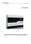
Download Installation Manual Of PV Energy Storage Machine
Transcript
Page 1/46 Installation Manual Of PV Energy Storage Machine Page 2/46 list 1 Brief Introduction ..........................................................................................................................4 1.1Preface ............................................................................................................................................................ 4 1.2Target Group ................................................................................................................................................... 4 1.3Product Description ........................................................................................................................................ 4 1.4 Safety Instructions ......................................................................................................................................... 5 2 Safety .............................................................................................................................................5 2.1 Purpose Use ................................................................................................................................................... 5 2.2 Safety Measure .............................................................................................................................................. 6 2.3 Symbols introduction on the energy storage machine .................................................................................. 7 3 Product Description .......................................................................................................................8 3.1 Growatt SP series inverter ............................................................................................................................. 8 3.2 Label Explanation ........................................................................................................................................... 8 3.3 Size and weight .............................................................................................................................................. 9 3.4 The advantage of the unit of Growatt SP..................................................................................................... 10 4 Unpacking .................................................................................................................................... 10 5 Installation ................................................................................................................................... 11 5.1 Basic installation requirements.................................................................................................................... 11 5.2 Installation Instructions ............................................................................................................................... 12 5.3Storage System Connection Mode................................................................................................................ 15 5.4 System Electrical Connection ....................................................................................................................... 18 5.5 Grounding .................................................................................................................................................... 27 6 Commissioning ............................................................................................................................27 6.1 Commissioning of Energy storage machine ................................................................................................. 27 6.2 Operation modes ......................................................................................................................................... 28 6.3 LED AND LCD’S DISPLAY ............................................................................................................................... 29 6.4Communication............................................................................................................................................. 34 7 Start-up and shut down SP 2000 system......................................................................................37 7.1Start-up the SP 2000 system ......................................................................................................................... 37 7.2 Disconnect the SP 2000 system ................................................................................................................... 37 8 Attention of the installation environment, maintenance and cleaning .......................................37 9 Fault removal ...............................................................................................................................38 10 Manufacturer Warranty .............................................................................................................41 11 Decommissioning.......................................................................................................................42 11.1 Dismantling the energy storage ................................................................................................................. 42 11.2 Packing the energy storage machine ......................................................................................................... 42 11.3 Storing energy storage machine ................................................................................................................ 42 11.4 Disposing of the energy storage machine.................................................................................................. 43 12 Product specification ..............................................................................................................43 12.1 Growatt SP series energy storage machine product specification............................................................. 43 12.2 DC input terminal parameter ..................................................................................................................... 44 12.3 Torque ........................................................................................................................................................ 45 12.4 Appendix .................................................................................................................................................... 45 Page 3/46 13 Certificate .................................................................................................................................. 46 14 Contact ......................................................................................................................................46 Page 4/46 1 Brief Introduction 1.1Preface This manual will provide the users who use the PV Energy Storage Machine of Growatt SP Series of GROWATT NEW ENERGY TECHNOLOGY CO.LTD.SHENZHEN(Short for Growatt New Energy as below) with the detailed product information and the installation instructions. Please read this manual carefully and put this manual on some place where is convenient to installation, operation, obtain. Any modifications of Growatt new energy, we will not notify the user 1.2Target Group The energy storage machine must be installed by professional electrical personnel who have obtained the certification of the relevant departments. Installer can install energy storage machine of Growatt SP Series rapidly and troubleshooting, build communication system through read this manual carefully. If you have any questions in the process of installation, you can login in www.growatt.com and leave some message. Or you can call our 24-hour service hotline 0755-29467281/400-833-9981. 1.3Product Description The energy storage machine of Growatt SP Series is used to store excess energy generated by the photovoltaic cell panels in the battery, the excess energy can be sent to power grid through the energy storage machine and the inverter at night. The energy storage machine of Growatt SP Series adopts the conversion of topology in both directions, Can satisfy two kinds of work needs of charge and discharge. Overview: Page 5/46 Position Description A Tap on the marked area B LCD display screen C LED of status display D DC output E panel input F DC switch G Touch ground point of box H AC socket I The reserved antenna hole J Lead battery temperature test line and current transformer measurement line connector 1. 2. 3. 4. K LAN connector L RS232 cover board M battery power connecting pin N lithium BMS RS485 connector Safety Instructions Pease read this manual carefully before the installation, The company has the right not to quality assurance, If not according to the instructions of this manual for installation and cause equipment damage. All the operation and connection please professional electrical or mechanical engineer. During installation, Please don’t touch the other parts within the box All the electrical installation must comply with the local electrical safety standards 1.4 Safety Instructions 1)Pease read this manual carefully before the installation, The company has the right not to quality assurance, If not according to the instructions of this manual for installation and cause equipment damage. 2)All the operation and connection please professional electrical or mechanical engineer. 3)During installation, Please don’t touch the other parts within the box 4)All the electrical installation must comply with the local electrical safety standards 5)If equipments needs to maintain, Please contact with local specify system installation and maintenance personnel 6)Use the equipment to combined to grid needs to obtain the permission of local power supply department 7)When install PV modules in the daytime, Installer should cover the PV modules by opaque materials, Otherwise it will be dangerous as high terminal voltage of modules in the sunshine 2 Safety 2.1 Purpose Use The system chart of PV energy storage: Page 6/46 Chart 1.1 As shown above, A complete grid-connected system of PV storage consists of PV modules, storage machine, battery, PV inverter, utility grid and other components. In the PV energy storage system, energy storage machine and inverter are the key parts of component parts Attention: As the system refer to battery use, We must make sure ventilation of the service environment and temperature control in order to prevent the danger of battery explosion, Battery recommended installation environment must be strictly in accordance with the specification in IP20 environment, the pollution degree of the unit is PD2, meanwhile the temperature should be control in the 0-40℃ of indoor ventilation and the humidity should be 5%-85%. If the chosen PV modules needs to positive or negative ground connection, please contact with Growatt for technical support before installation. 2.2 Safety Measure Risk of high voltage! Relevant operation for professional personnel Please notice children, disabled, laypeople do not close Supervise and make sure children don’t play near the installation position of energy storage machine Risk of burns on the parts shell of energy storage machine ! During the work, Cover, shell around, radiator is likely to be hot Page 7/46 Energy storage machine exists radiation maybe affect health! Don’t stay a long time within 20cm range from energy storage machine Energy storage machine ground connection Please ensure energy storage machine ground connection is reliable for make sure people’s safety 2.3 Symbols introduction on the energy storage machine symbol description Caution :Risk of electrical shock! Caution : hot surface Caution: risk of danger Danger to life due to high voltage in SP 2000 There is residual voltage in SP 2000, SP 2000 requires 2 minutes to discharge. • Please wait 2 minutes before you open the upper lid or the DC lid. Protective conductor terminal Direct Current(DC) Alternating Current(AC) The machine complies with the requirements of the applicable CE guidelines Refer to the operating instructions. Page 8/46 3 Product Description 3.1 Growatt SP series inverter Marks of energy storage machine Mark Description Tap symbol Explanation Operation of display screen (Detailed in section 6) Green light on Status symbol of energy storage machine Red light on Red blinking 3.2 Label Explanation Label contains the following information: The type of product, Energy storage machine run normally, charge or discharge fault state light 1.Alarm state 2.Software updating Page 9/46 Description of label: the type of product Growatt SP2000 Input voltage range 100-580Vdc Max input and output power through 6000W SP2000 Max input current 30A Max charging and discharging power 2000W Output voltage while discharging 150-500Vdc Max charge and discharge current of energy 10A storage machine Battery voltage range 46-58Vdc Max charge and discharge current of ≤45A battery Lead Suitable battery types battery and lithium battery Recommend battery capacity range 90-200Ah The discharge depth control of battery Discharge capacity at night Lead battery50%DOD Lithium battery80%DOD 2-9kWh Safety certification CE LED status display Display LCD information display Level of protection IP20 Communication type RS232/LAN/WIFI(choice) 3.3 Size and weight Chart 3.1 Page 10/46 Growatt SP 2000 A(mm) B(mm) C(mm) weight(kg) 482 355 166 13.2 3.4 The advantage of the unit of Growatt SP Features below: Adapt to existing PV system with general inverter and new system Battery management system, To satisfy pattern of Lead battery and lithium battery Wide working voltage range:100V~580V。 Easy installation。 Max efficiency 94%。 Satisfy RS232,WIFI wireless and LAN communication monitoring 4 Unpacking Please check whether external damage to the goods before unpacking After unpacking, Please check whether the unit damage or missing parts, If it is happen, Please contact with supplier. Energy storage machine of Growatt SP series and accessories as follows: A B C D E Chart 4.1 Item Number Description A 1 Energy storage machine of Growatt SP series B 1 User Manual C 1 electric current sensor (Standard wire length 5m) D 1 Battery temperature detection line(Standard wire length 1.5m for lead-acid battery) E 4 M6 Setscrew F Page 11/46 F 1 Paper board(installation guide) 5 Installation 5.1 Basic installation requirements A The installation location must be suitable for the energy storage machine’s weight for a long period time(Please refer to the specification in chapter 10 about the weight of energy storage machine ) B The installation location must conforms with dimension of energy storage machine C Do not install the unit on structures constructed of flammable or thermo labile materials D The Ingress Protection rate is IP20 and the pollution degree is PD2, The install area shall be generally conditioned in term of temperature, humidity and air filtration. E Battery installation option is not far below the position of energy storage machine F The humidity of the installation location should be 5 ~ 85% G The ambient temperature should be 0℃ ~40 ℃ H Energy storage machine can be installed in vertical or lean back on plane, Please refer to the below I Installation position shall not prevent access to the disconnection means. Chart 5.1 I In order to ensure machine can run normally and easy to operate, please pay attention to provide adequate space for energy storage machine, Please refer to below: Page 12/46 Chart 5.2 J Do not install the machine near television antenna or any other antennas and antenna cables K Don’t install the machine in the living area L Be sure that the machine is out of the children’s reach 5.2 Installation Instructions Note:Before installation, Please confirm whether it is the first install system or have already installed system after installed the inverter, If it is the first install system, Please according to the installation manual of inverter, Installing the inverter first, If not, Please installation as the following steps. 5.2.1 Installation Layout The installation layout of energy storage machine at home as following: The energy storage machine SP 2000 needs to install near bus position(The red line is sampling line of Sensor as below, The wire length is 5m(no more than 15m),Installation position needs to consider distance less it), Page 13/46 Chart 5.3 The whole system diagram of PV online storage is as follows : Chart 5.4 5.2.2 Installation of energy storage machine Page 14/46 1. Project the machine’s probably size on the wall, the thickness of wall for SP 2000 must be not less than 60mm. 2. Make sure the drill position, use paper board(installation guide), put the paper board cling to the wall, make sure the top edge of paper board is level(As the chart 5.5a below) 3. Mark four points at the wall via the hole of the paper board, then remove the paper board. 4. 5. 6. 7. 8. Drill four Ф8 holes at the mark point, the depth is not less than 55mm. Knock four explosion bolt intoФ8 holes(As the chart 5.5b below) Hang the energy storage machine on the four setscrews(As the chart 5.5c below) Lock the nut of setscrew(As the chart 5.5d below) The whole installation has finished(As the chart 5.5e below) a) b) c) Page 15/46 d) e) Chart 5.5 5.3Storage System Connection Mode 5.3.1 Difference between Traditional Photovoltaic System and Storage System Growatt SP 2000 series storage plus can be connected to single-phase grid-connected inverter to build a storage-function system. Every string can be connected to one SP 2000. If you have double MPPTs to be connected to SP 2000 respectively, every MPPT connects one will be feasible. The traditional single-phase inverter system is shown as below: Chart 5.6 Traditional single-phase inverter system consists of PV panels, PV inverter, load and power grid. The inverter supplies the power generated by solar panels to household load. Extra electricity will be fed to the grid when generated power is more than family load needs; otherwise inverter will get power from grid for supplement. PV Storage System with the storage plus is shown as below: Page 16/46 Chart 5.7 Compared with the traditional photovoltaic system, a storage-control device SP 2000, battery cells (battery voltage should be between 46V to 58V, both lead-acid and lithium battery is ok) and a sensor for information collection have been added into the Storage System (Notice: Sensor must be installed close to the grid side). 5.3.2 Storage System installation with Dual-MPPT inverter As for connection with single MPPT inverter, you can refer to chart 5.7 for installation. When installing the storage system with dual MPPT inverter, if you just upgrade one MPPT to execute storage function, you are advised to install the Storage Plus to the MPPT which generates greater power. Installation diagram as below: Chart 5.8 Connect one PV string to the Storage Plus, and then to one MPPT of the inverter. While connect the other PV string direct to the input terminal of the inverter. If both MPPTs are to be upgraded to execute storage function, installation should be done as below: Page 17/46 Chart 5.9 Notice: During the installations above ,please pay attention to the installation position of the sensor. 5.3.3 Installation steps of Upgrading existing PV system Steps to add the storage system into the original installed PV inverter system are shown as follow: Step 1: If inverter is equipped with a DC switch, please turn the DC switch to Off and ensure that the DC switch on the Storage Plus stays at Off status at the same time. Then unplug the terminal connected to the inverter from PV panels, and connect it to the Input terminal of Storage Plus. Chart 5.10 Step 2: Connect the output of Storage Plus to the input of your PV inverter, as the diagram show: Chart 5.11 Page 18/46 Step3: Connect the battery to Storage Plus, you can refer to 5.4.7 for connection of battery. Chart 5.12 Step 4: Buckle the sensor to the residential user inlet wires, at the same time plug the AC PLUG on the Storage Plus to electricity, and finally the entire system is ready to work smoothly. Chart 5.13 5.4 System Electrical Connection 5.4.1 Storage Plus PV Connection 1. Insure correct polarity before connecting the PV input. Reverse positive or negative polarities may cause unrecoverable damage. Insure that the short-current of PV string should not exceed the max input current of the Storage Plus. 2. The diagrams below show the PV connection way. Attention, the connectors (male and female connectors)are in paired. The connectors for PV arrays and inverters are H4 or MC4 standard. Page 19/46 Chart 5.14 Before connect Chart 5.15 after connect 3. The maximum input current value as the table shows below: Type Max PV input current Max output current to inverter 30A 30A Growatt SP 2000 Remark: 2 We suggest you use the cable ≥4mm /12 AWG to connect. 5.4.2 Connection of Temperature sensor for Lead-acid battery 1. Please confirm the battery type before connection. For the installation of Lead-acid battery, you need to use the temperature sensor, while lithium battery can connect direct to BMS. 2. Open the cover plate at the terminal before connection. Caution: before open the cover, you must make sure all the power is off, and must be operated by professional person. When the power is not off, you can’t open the cover because danger of electronic shock. . Page 20/46 Chart 5.16 As pictured above, with the top cap open, take the white 2PIN female plug of battery temperature sensor through the cover plate, and insert it into the 2PIN male plug marked with NTC/SENSOR. The other terminal will stick to the battery cabinet. Remark: temperature detection wire (1.5m in length) specifications: UL1332 26 AWG TS 200℃ 300V. 5.4.3 Installation of sensor connection There is a current transformer in sp 2000 monitoring the power consumption situation of residential users. The current transformer should be installed at the wire-inlet side. Chart 5.17 Installation of Sensor for lead-acid battery as the diagram above. When it is unnecessary to install the NTC battery, please insert the RJ45 plug of the sensor into the section marked with the words: NTC/SENSOR. Page 21/46 Chart 5.18 The other terminal of CT sensor will be installed in distribution box. Caution: before open the cover, you must make sure all the power is off, and must be operated by professional person. When the power is not off, you can’t open the cover because danger of electronic shock. Remark: Sensor lead wire (5m in length) specification: RJ45, standard LAN line (one end with 8P modular plug, the other connected with sensor). But if the length is not enough, customer can add cable, so the length can be increased to 15m, the operation is as follow chart: Chart 5.19 During the actual operation, please pay attention to the installation of current transformer as the diagram shows below: Page 22/46 Chart 5.20 As illustrated above, open the current transformer and you can see an arrow labeled on it indicating the direction of current. Put the live wire among the under-detection wires onto the current transformer. After latching the current transformer, the installation has been finished Notice: the direction (from K to L) of the arrow on the current transformer is corresponding to the direction of the current in live wire from load to the grid. Sensor needs to be placed in the power distribution cabinet 5.4.4 Connection of LAN Monitoring If you need to monitor the Storage Plus via LAN, the installation steps are as follow: 1. Make sure the cover plate is removed. 2. Make the LAN line go through the second hole of the cover plate, and insert it into the plug under the labeled words LAN/RS485. Chart 5.21 Remark: LAN line specification: RJ45, standard LAN line (with 8P modular plug at both ends). 5.4.5 Battery Power Connection Page 23/46 1. Insure the polarity is correct before connecting to battery input. 2. Open the cover plate at the terminal before connection. 3. Battery connection area located on the right side above the bottom plate as the diagram below: Chart 5.22 Electrical connection of battery is shown as below: Chart 5.23 According to the battery power, you should use Cable AWG8 or Cable 2*AWG10 to connect. And the length of this cable not more than 1.5m. Note:when we connect lead-acid battery to SP2000, we should add a bat fuse between SP2000 and lead-acid battery. Also we suggest the max current of bat fuse is 75A (fuse’s voltage must above 60V), the follow chart is how to add a bat fuse: Chart 5.24 Cable 1 length add cable 2 length should not more than 1.5m. Page 24/46 5.4.6 Connection with BMS system of Lithium Battery When connect to lithium battery with a BMS system, please connect the battery BMS system to the COM of the Storage Plus via LAN line. Installation steps are as follow: 1. Firstly please confirm the distance between battery and Storage Plus, and purchase a LAN line in spare length, both ends of LAN are RJ45 terminals. 2. Insure the battery is in a dormant state before connection between Storage Plus and lithium battery. 3. Severally plug one RJ45 modular plug of the LAN line(RJ45 Standard LAN) to the Storage Plus. Chart 5.25 5.4.7 Connection to Lead-acid Battery Before connection to the lead-acid battery, please confirm the items below: 1. Main output voltage of lead-acid battery is 48V. 2. Total Capacity of lead-acid battery is no less than 80AH. 3. The installation cabinet of lead-acid is under ventilation condition. Installation of lead-acid battery is shown as follow: Chart 5.26 Page 25/46 Step 1. Connect to the positive pole and negative pole of lead-acid battery cabinet(we suggest you use terminals like KST(http://www.kstinc.com.cn/), BMC2S of the kinds )sectional area of connected cable should be more than 8mm2。 Step 2. Paste the NTC conductor used to detect ambient temperature of lead-acid battery onto the top of lead-acid battery cabinet. After accomplishing the two steps above, the connection of lead-acid battery is completed. 5.4.8 Recommendatory connection: Connection Between SP2000 and Darfon Lithium Battery Darfon is qualified lithium battery manufacturer of Growatt. As to the detailed operation of Darfon Lithium battery you can refer to user manual of Darfon lithium battery in the packing box. Connection between SP 2000 and Darfon battery as follow: 1. Firstly insure the’ status’ LED indicator of lithium battery is in the extinguished status. 2. Prepare to connect with cable and LAN of the Battery, the sectional area of the cable should be more than 8mm2, you are advised to use the connector within the battery packing box to connect the battery and we require the RJ45 modular plug LAN line. 3. Connection of terminals is shown as below: Chart 5.27 After all connections done , gently press the ‘wake up’ KEY of the lithium battery. While the ‘status’ LED indicator turns green, the battery starts working. Note:customer must connect lithium battery which was qualified by Growatt , otherwise it will bring danger. All the lithium battery which was qualified by Growatt has a battery fuse inside the battery box. 5.4.9 Storage Plus AC power supply connection Preparations before connection: A make sure the AC plug input have Type B RCD(Residual current detection or monitoring) B measure the grid voltage and frequency and make sure the voltage is 220/230Vac , the frequency is 50/60Hz in single phase. C Connect the AC cable with safety regulation to the AC PLUG section. The cable must be inserted in Page 26/46 the overvoltage category 2 places, namely the home row insert. We suggest the cable ≥3*0.75mm2 to connect. Chart 5.28 Chart 5.29 Chart 5.30 5.4.10 Storage Plus grounding SP 2000 must be grounded by cable, the grounding point is showed as follow, and the minimum grounding cable wire diameter is 10.0mm2. Page 27/46 Chart 5.31 5.5 Grounding PV Array Grounding Grounding conductor of PV panel brackets must be firmly connected to earth at PV array side and inverter side and SP 2000 side. The sectional area of grounding conductor should be equal to the sectional area of DC grounding conductor. The minimum wire diameter is 10.0mm2. DC Grounding Select the DC Grounding mode according to the local standard and use the PV grounding terminal box and DC Grounding wires of the same specification. Grounding Device If the positive pole or the negative pole of PV array need to be grounded in the PV system, the inverter output should be insulated by Isolation Transformer. Isolation transformer must conform to IEC62109-1,-2 standard. Connection as below: Chart 5.32 6 Commissioning 6.1 Commissioning of Energy storage machine 1) 2) 3) Connect the input side terminal to PV modules. Connect the output side terminal to PV inverters. Connect the AC plug to grid. Page 28/46 Chart 6.1 4) 5) 6) 7) If the energy storage machine’s input voltage is 230±15%V and meanwhile fail to connect battery.LCD will display information as follows: storage plus standby status information. LCD will disply“bat voltage low”status. Please check all the information on the LCD, through knocking you’ll see various parameters Turn off DC switch and connect to battery, turn on inverter’s DC switch, both energy storage machine and inverter will operate automatically. In normal contra variant mode, LCD would scroll display the state information, LED area would display the current state. The green LED light would turn on constantly in the same time. Finish commissioning. 6.2 Operation modes 6.2.1 Normal charge mode When daytime with abundant sunlight, energy storage machine can work in normal charge mode. ● When DC voltage is more than 150V,The energy storage machine detected the inverter has countercurrent power flow to the grid, The machine would transform the redundant energy exist in PV panel into electric and store into the battery, the green LED light will be lighten at the moment ● When DC voltage is less than 130V, The energy storage machine will quit the normal charge mode automatically and turn into standby status, until the PV voltage up to grade again and there is countercurrent power, the energy storage machine would turn into normal charge mode automatically. ● When DC voltage is more than 150V,while The energy storage machine fail to detect the inverter has countercurrent power flow to the grid, the energy storage machine won’t start charge, and in the standby status. NOTICE: Must connect to AC, or the energy storage machine won’t start up. 6.2.2 Normal discharge mode When the solar energy is shortage at night, though battery capacity is completely over plus, then the energy storage machine can work in normal discharge mode. ● When DC input voltage is less than 100V, The energy storage machine detected the inverter has downstream power flow from grid to load, the energy storage machine will extract energy from the energy storage battery side, and provide it to inverter as the photovoltaic panel’s mode, meanwhile the inverter transform the DC current into AC current and feed it to load, the green LED light will be lighten at the moment. ● When DC voltage is less than 100V, The energy storage machine fail to detect the inverter exist downstream power flow from grid to load, then the energy storage machine will be standby state, and won’t provide any power. ● When DC voltage is more than 120V,the energy storage machine will transform discharge state to standby state. NOTICE: Must connect to AC, or the energy storage machine won’t start up. Page 29/46 6.2.3 Fault mode The energy storage machine’s intelligent control system could monitoring and adjustment system’s status continuously, when energy storage machine monitoring anything unexpected happen, such as system fault or machine fault ,the LCD will display the fault information, in fault mode, the LED light will be lighten. NOTICE: a)The detail’s fault information please refer to 9.1 b)Some fault information is in order to remind users that might have some faults occurred in inverter side. 6.2.4 Shutdown mode Under normally circumstances, the energy storage machine will be standby state all the time, If need energy storage machine to stop working, you must disconnect the machine’s providing, then the energy storage machine will turn into shutdown mode automatically. The following is the shutdown procedure: First: showdown the PV side, turn off the DC SWITCH of SP 2000. Second: Pull the AC PLUG from the AC grid. Then you can see the both LED and LCD of SP 2000 are off. Third: Pull the BMC connector form battery. NOTICE: After all the action are done, you still have to wait for 2 minutes. 6.3 LED AND LCD’S DISPLAY 6.3.1 LED display area Chart 6.2 location A B description represent photovoltaic panel storage system(include the machine and battery) Page 30/46 C D E F home use load contracted notation PV inverter Power grid each of power direction indicating arrow 6.3.2 Each status’ LED light indication schematic State one: before dawn, The energy stored in the battery is ran out, then the amount of home use load energy needed by the power grid to supply, the whole LED light operate indication schematic as follow (for example): Chart 6.3 State two, in the morning and the sun rises, the PV panel’s energy increase gradually, the photovoltaic panel start to supply energy to users through the inverter, lead to get power from grid less and less(or when the battery is full in the daytime, while solar energy is insufficient ), the whole LED light operate indication schematic as follow: Chart 6.4 State three: with the sunlight become stronger and stronger, the PV panel’s energy increase gradually, the power of the photovoltaic panel create not only satisfy the home use load, but also feed the power to grid, The SP start at the moment, and charge to the battery, decrease the countercurrent, the whole LED light operate indication schematic as follow: Page 31/46 Chart 6.5 State four: with the sunlight become more stronger and stronger, the PV panel’s energy increase gradually, the power of the photovoltaic panel creates not only satisfy the home use load and SP, but also feed the redundant power to grid, the whole LED light operate indication schematic as follow: Chart 6.6 State five: increased with time, battery of SP2000 will be fully, at that time, the power of the photovoltaic panel creates not only satisfy the home use load, but also feed the redundant power to grid, the whole LED light operate indication schematic as follow: Chart 6.7 State six: The same situation as state two, with time goes by, the sun goes down to the hill slowly, the power of the photovoltaic panel creates can’t satisfy the home use load ever, then the power grid would supplement the lack of the part. the whole LED light operate indication schematic as follow: Page 32/46 Chart 6.8 State seven: when the sun goes down to hill completely, the photovoltaic panel doesn’t create power anymore,The SP has detected the condition of the load, and then restart discharge mode to satisfy home use’s load, the whole LED light operate indication schematic as follow: Chart 6.9 State eight: At night, when the household electricity increase, exceed the power of the SP create, in order to satisfy the home use’s load ,the power grid will replenish the energy of the SP’s output insufficient, the whole LED light operate indication schematic as follow: Chart 6.10 6.3.3 LCD display column LCD display column is used to show the current state, basic information and fault information. Also include se the Page 33/46 language, COM address and time. On default condition will take turns to display the information. Chart 6.10 location A B C description display the SP’s state, include(standby, charging……) Various of information display column State indication light, used to tell the normal or fault state. The A line’s concluding information as follow: 1、 Standby state: The machine is in standby state, not conduct charge-discharge operation. 2、 Charging state: The machine is in PV to recharge the battery’s state. 3、 Discharging state:The machine is in battery discharge to inverter’s state. 4、 Warning state: The machine has warning information, but doesn’t affect the normal operation of the machine. If there is warning information, LCD will alternate display the current state and warning information (state and warning every 5 seconds). 5、 Fault state :The machine has fault information, the machine will be in stopped operational protection state. 6、 Programming state:The machine is in burn program’s state. The B line’s concluding information as follow: In normal, it will paging automatically, when receive the sound control’s command, the order of the paging information as follow: 1. No sound control command: Vb/Cb: . V/ Vpv/Vac: / V Ppv: . WPcharge: . W Pdischa: . W Vo_discha: V Ec_day: . kWh Ed_day: . kWhP_Grid: . W Vb/Cb: . V/ (every page stops 5s) Note:Vb means the voltage of battery. Cb means the capacity of battery. Vpv is the voltage of PV array input. Vac is the voltage of grid. Ppv means the input PV power. Pcharge means the charging power of SP 2000. Pdischa means the discharging power of SP 2000. Vo_discha means the output voltage of SP 2000. Ec_day means the current daily charging capacity Page 34/46 Ed_day means the current daily discharging capacity P_Grid means the power to grid, if the data is positive, it means there is power from PV inverter to grid, otherwise , if the data is negative, it means there is power from grid to local load. 2. single sound control command Vb/Cb: . V/ Vpv/Vac: / V Ppv: . WPcharge: . W Pdischa: . W Vo_discha: V Ec_day: . kWh Ed_day: . kWhP_Grid: . WVbus: . VSerNo: Model: FW Version: COM Address: 20 / / : Setting Vb/Cb: . V/ % Note(additional): SerNo means the serial number. Model means the model of SP 2000, Different model corresponding to different battery. FW version is the software version of SP 2000. Setting is the setting window of SP 2000. 20 / / is system time of SP 2000. 3. In the following pages knock on twice in a row, current page will remain two minutes Vb/Cb: . V/ Vpv/Vac: / V Ppv: . W Pcharge: . W Pdischa: . W Vo_discha: V Ec_day: . kWh Ed_day: . kWh P_Grid: . W Vbus: . V SerNo: Model: COM Address: 20 / / : 4. IN FWVersion page,knock on twice continuously will display Build version 5. In Set Window page,knock on twice continuously will enter the LCD setting unction: Set Window(knock on twice continuously) Input 123(finish entering the password, knock three times) Battery Set language : Com Address: Battery set Accuracy of measurement Display value and actual value may have deviations, can’t be billing criteria. The Inverter measured value is used to control the parallel grid usage, not for accurate calibration. 6.4Communication 6.4.1 Use the PlusBus to set the storage machine About PlusBus software, when you needed, please download from official website. of Growatt Before use RS232 communication, you should make sure the follow PIN1 and PIN2 are OFF: Page 35/46 The wiring diagram is as follows: Chart 6.11 6.4.2 The SP’s monitoring The SP provide LAN and RS232 two kinds of interface. Users can through the following two communication solution to monitor the SP. NOTE: these two kinds of monitoring, Can only be used by the monitor of Growatt’s Shine server software provided by the company. Scheme A : Through RS232 interface connect to WIFI, use computer terminal for data monitoring. Chart 6.12 Page 36/46 Before use WIFI communication, you should make sure the follow PIN1 or PIN2 is ON: Scheme B : Through LAN interface connect to computer, use computer terminal for data monitoring. Chart 6.13 NOTICE: the length of LAN cable is decided by users themselves according to actual situation Page 37/46 7 Start-up and shut down SP 2000 system 7.1Start-up the SP 2000 system Connect the AC circuit breaker Insert AC PLUG,connect AC.the SP according the situation start-up model to judge and operate automatically. 7.2 Disconnect the SP 2000 system 1. 2. 3. 4. 5. Disconnect the DC circuit breaker Disconnect the inverter Disconnect the battery Pull up AC PLUG connection Waiting until LED,LCD display have gone out, the SP is shut down completely 8 Attention of the installation environment, maintenance and cleaning Heat dissipation performance is very important when Energy storage machine work under the environment of high temperature, better heat dissipation can reduce the possibility of energy storage machine stops working. Growatt SP series storage machine without fan so belongs to natural cooling, hot air from the top of the radiator, tie-in battery, use environment for IP20, please pay attention to the temperature of the installation environment, to ensure that the battery's safety and the normal work of the machine. When use battery, please pay attention to the follow information: Caution: Do not dispose of batteries in a fire. The batteries may explode. Caution: Do not open or damage batteries. Released electrolyte is harmful to the skin and eyes. It may be toxic. Caution: A battery can present a risk of electrical shock and high short-circuit current. The following precautions should be observed when working on batteries: a) Remove watches, rings or other metal objects. b) Use tools with insulated handles. c) Wear rubber gloves and boots. d) Do not lay tools or metal parts on top of batteries. e) Disconnect charging source prior to connecting or disconnecting battery terminals. f) Determine if battery is inadvertently grounded. If inadvertently grounded, remove source from ground. Contact with any part of a grounded battery can result in electrical shock. The likelihood of such shock can be reduced if such grounds are removed during installation and maintenance (applicable to equipment and remote battery supplies not having a grounded supply circuit). If the storage machine doesn't work for overheating too cold, solve it according to the following methods confirm whether the radiator air duct installation is reasonable, choose the appropriate position before installation. If is lead-acid batteries, confirming the NTC battery is in a good installation confirm whether the battery temperature is too high, the battery temperature too high can also lead to energy storage machine fail to work normally, at this point, to ventilation, cooling or still handle to the battery, please. If temperature is low, also can appear the battery low temperature protection, the battery will start with small load in low temperature output, when after temperature back to normal can work normally, Page 38/46 please be patient at this time if the temperature is too low, it is possible the battery low temperature protection rather than the output, at this time, please pay attention to the working temperature range listed in the specifications of the book. Servicing of batteries should be performed or supervised by personnel knowledgeable about batteries and the required precautions. When replacing batteries, replace with the same type and number of batteries or battery packs. General instructions regarding removal and installation of batteries. Remark: all of above action should be operated by professional person, if you want to do these works, you must make sure all the power of storage system is off, for example: turn off all the DC switch, plug off the AC Cable and battery power etc. 9 Fault removal Our products are carried out with strict tests before they take out, if the operation difficulties in the process of installation, please log on to www.ginverter.com website, view the Q&A program. When energy storage machine fault happens, please inform our company, and to provide energy storage machine related information, we will have a professional after-sales service personnel to answer you. what you need to provide the information about the SP 2000 including : About the energy storage machine: serial number model information about the LCD display brief description of problems the battery voltage the dc input voltage can you retell the failure problem? If you can, what kind of a situation Did the problem happen in the past? what’s the reason about this problem? about The solar photovoltaic panels The manufacturer name and model of solar photovoltaic panels The output power of photovoltaic solar panels; Solar photovoltaic panel output voltage; Solar photovoltaic panels MPPT output voltage The MPPT output current of photovoltaic solar panels; The number of solar photovoltaic panels about the battery The manufacturer name and model of battery capacity of battery he total output voltage of the battery the time you buy Battery and frequency you use it 9.1 System fault information list and troubleshooting suggestions LCD display Fault description Fault When SP Suggestion Page 39/46 Status Error: 100 Firmware version mismatch Firmware mismatch version Fault Update FW with right version Error: 101 Communication fault M3 cannot receive data from DSP Fault 1. Check communication cable 2. Restart Solar Plus BMS COM Fault Communication fault Communication failure between M3 and BMS Fault 1. Check 485 cable between SP and battery 2. Check if battery is sleeping BMS Error: xxx BMS failure and neither charge and discharge is allowed BMS failure and neither charge and discharge is allowed Fault Depend on BMS error code Error: 116 Over current protection triggered by Trip Zone Over-current Fault 1. Check PV input terminals 2. Restart Solar Plus Error: 117 Over current protected by software Over-current Fault 1. Restart Solar Plus Error: 118 Over BUS-voltage protection BUS voltage high Fault 1. Check battery terminals when charge 2. Check dummy load when discharge Error: 119 Communication fault DSP cannot receive data from M3 Fault 1. Check communication cable 2. Restart Solar Plus Error: 119 Communication fault DSP cannot receive data from M3 Fault 3. Check communication cable 4. Restart Solar Plus PV Voltage High PV Voltage High PV voltage higher than 580V for 100ms Fault Check PV input voltage PV Short-circuit PV input short-circuited PV voltage lower than 20V and PV current higher than 5A Fault 1. Check PV terminals Battery reversed Battery terminals reversed PV voltage lower than -10V for 100ms Fault 1. Check terminals input battery Page 40/46 PV Access PV input and Wrong discharge output of Solar Plus misconnected PV voltage lower than 20V and BUCK voltage higher than 50V and cannot be dragged down by 30s dummy load on Fault 1. Check PV input and BUCK output terminals PV Reversed PV terminals reversed PV voltage check signal is higher than 2.57V Fault Check PV terminals L-N Reversed AC terminals reversed The voltage between N and Earth higher than 100V for 100ms Fault Check AC terminals No AC AC voltage low AC voltage lower than 50V Fault Check AC voltage NTC Open NTC open NTC open Fault Check NTC terminals Fuse Open Fuse Open Vdrop on fuse higher than 10V for 200ms Fault Check fuse Battery Open Battery terminal Battery voltage open (only for sampled by SP is 10V lithium battery) lower or higher than BMS Fault Check battery terminal MPPT Trouble MPPT Trouble Exit discharge for no MPPT five times Fault Check state inverter SS Timeout Soft start run out of time Bus or BUCK voltage cannot get target value after 2min soft start Fault Check voltage sample of BUS or BUCK BMS Error: xxx BMS failure and BMS failure and either either charge or charge or discharge is discharge is allowed allowed Warning Depend on BMS error code Bat voltage low Battery low of PV voltage Battery voltage lower than 44V for 100ms Warning Check battery terminals Bat T Battery Outrange temperature out of specified range for charge or discharge Battery temperature out of specified range for charge or discharge(range is settable) Warning Check battery temperature No AC power flow Power flow between grid and user lower than 50W for 10 minutes Warning Check if AC current sensor is connected well No AC power flow Page 41/46 10 Manufacturer Warranty This certificate represents a 5 year warranty for the Growatt products listed below. Possession of this certificate validates a standard factory warranty of 5 years from the date of purchase. Warranted products This warranty is applicable solely to the following products: Growatt SP 2000. Limited Product Warranty (Applicable under normal application, installation, use and service conditions)Growatt warrants the above listed products to be free from defects and/or failure specified for a period not exceeding five (5) years from the date of sale as shown in the Proof of Purchase to the Original purchaser. The warranties described in these “Limited Warranty” are exclusive and are expressly in lieu of and exclude all other warranties, whether written, oral, expresser implied, including but not limited to, warranties of merchantability and of fitness for a particular purpose, use ,or application, and all other obligations or liabilities on the part of GROWATT , unless such other obligations or liabilities are expressly agreed to it in writing signed and approved by GROWATT , GROWATT shall have no responsibility or liability whatsoever for damage or injury to persons or property, or for other loss or injury resulting from any cause whatsoever arising out of or related to the modules, including, without limitation, any defects in the modules or from use or installation. Under no circumstances shall GROWATT be liable for incidental, consequential or special damages howsoever caused; loss of use, loss of production, loss of revenues are therefore specifically and without limitation excluded to the extent legally permissible, GROWATT ’s aggregate liability, if any, in damages or otherwise, shall not exceed the invoice as paid by the customer. The “Limited Product Warranty” described above shall not apply to, and Growatt shall have no obligation of any kind whatsoever with respect to, any machine which has been subjected to: Misuse, abuse, neglect or accident; Alteration, improper installation or application; Unauthorized modification or attempted repairs; Insufficient ventilation of the product; Transport damage; Breaking of the original manufacturers seal; Non-observance of Growatt installation and maintenance instruction; Failure to observe the applicable safety regulations Power failure surges, lighting, flood, fire, exposure to incorrect use, negligence, accident, force majeure, explosion, terrorist act, vandalism or damage caused by incorrect installation, modification or extreme weather conditions or other circumstances not reasonably attributable to Growatt. The warranty shall also cease to apply if the product cannot be correctly identified as the product of Growatt. Warranty claims will not be honored if the type of serial number on the machines have been altered, removed or rendered illegible. Page 42/46 Liability The liability of Growatt in respect of any defects in its machines shall be limited to compliance with the obligations as stated in these terms and conditions of warranty. Maximum liability shall be limited to the sale price of the product. Growatt shall accept no liability for loss of profit, resultant of indirect damage, any loss of electrical power and / or compensation of energy suppliers within the express meaning of that term. The warranty rights as meant herein are not transferable or assignable to any third party excepting the named warranty holder. Warranty Conditions If a device becomes defective during the agreed Growatt factory warranty period and provided that it will not be impossible or unreasonable, the device will be, as selected by Growatt: 1、 Shipped to a Growatt service center for repair; 2、 Repaired on-site; 3、 Exchanged for a replacement device of equivalent value according to model and age. The warranty shall not cover transportation costs in connection with the return of defective modules. The cost of the installation or reinstallation of the modules shall also be expressly excluded as are all other related logistical and process costs incurred by all parties in relation to this warranty claim. 11 Decommissioning 11.1 Dismantling the energy storage 1. 2. Disconnect the storage machine such as mentioned in section 7。 Disconnect the upper cable of the storage machine watch out the SP’s shell heat and prevent to scald wait 20 minutes until the SP cooling and then to disassembly! 3. 4. Unscrew all the connecting cable Unscrew the radiator and wall-mounted’s anchor screw and then take down the machine from wall 11.2 Packing the energy storage machine Usually placed energy storage machine in the packing box with tape sealing, If the energy storage machine cannot reoccupy, You can choose a cheap carton for packaging. Carton requirements must meet the size of the inverter and can support energy storage machine overall weight. 11.3 Storing energy storage machine Store the energy storage machine in a dry place where ambient temperatures are always between - Page 43/46 25°C and +60°C 11.4 Disposing of the energy storage machine Do not dispose of energy storage machine together with household waste. Please accordance with the disposal regulations for electronic waste which apply at the installation site at that time. Ensure that the old unit and, where applicable, any accessories are disposed of in a proper manner 12 Product specification 12.1 Growatt SP series energy storage machine product specification Model Specification Growatt-SP2000 PV array input and output data: Input PV voltage range 100V~580VDC Max input current 30A *1 Max charging and discharging power 2000W Full load input DC voltage range 200V~450VDC output voltage discharging 150V~500VDC while Rated output voltage(mpp voltage for inverter) 380V Max charging and discharging current of SP2000 10A Rated output current 5.3A Number of independent MPP trackers/strings per MPP tracker 1/3 Output strings from SP2000 to inverter 2 Battery data Battery normal voltage 48V(lead-acid battery)/51.5V(Darfon lithium Page 44/46 battery) Battery voltage range 46V~58VDC Max charging voltage 57VDC/58VDC*2 Max charging current ≤45A Max discharging current ≤45A Type of battery Lead-acid battery/Lithium battery) Battery capacity 90~200AH 50% DOD/80% DOD*3 Deep of discharge daily night consumption electricity 2~9KWH Others: Maximum efficiency 94.0% Input grid voltage range(single phase) 230Vac±15% Operating temperature range: 0℃~+40℃ Altitude 2000m Cooling concept Natural Environmental Rating Protection Noise emission (typical) IP20 (indoor used) ≤40dB Certificates and approvals: CE over voltage protection yes Low voltage protection yes over current protection yes over load protection yes Output protection current short PV and battery reverse polarity protection Warranty: Connection for PV array side Connection for battery communication: display Dimensions(W/H/D) Weight yes yes (Five years) H4/MC4(opt) Screw terminal RS232/LAN/WIFI(opt) LED+LCD 482/355/166 13.2kg Page 45/46 12.2 DC input terminal parameter H4 specification: Rated current (90 2.5mm2/14AWG 4mm2/12 AWG 6mm2/10 AWG 10mm2/8AWG 32A 40A 44A 65A ℃ environment) Nominal system voltage 600V DC(UL) 600V DC(TUV) Contact resistance 0.25mΩ(model) Protection grade IP68 Socket contact materials Copper, tin Insulation materials Thermoplastics UL94 V-0 Ambient temperature range -40℃ to +90℃ Wire stripping length 7.0mm(9/32) Cable casing diameter 4.5 to 7.8mm(3/16: to 5/16”) 12.3 Torque Upper cover screws 1.3Nm(10.8 1bf.in) Shell and RS232screws 0.7Nm(6.2 1bf.in) Dc connector 1.8Nm(16.0 1bf.in) M6 screwdriver 2Nm(18 1bf.in) Grounding screw 2Nm(18 1bf.in) 12.4 Appendix The following chart is the energy storage machine optional appendix list, if there is a need please contact the Growatt New Energy Technology Co., Ltd or dealer orders. name description GROWATT P/N Shine Webbox Communication data record MR00.0001700 Shine Vision receiver Receptor of Communication data record MR00.0000201 Shine Vision emitter Launchers of Communication data record MR00.0000601 Zigbee COM interface 200.0007000 Wi-Fi COM interface MR00.0001400 Bluetooth COM interface MR00.0002200 Page 46/46 13 Certificate Growatt SP2000 apply within the scope of the world, So the inverter have to satisfy different countries and regions of different safety standards model Growatt SP2000 Certificate CE,SAA,RCM 14 Contact If you have technical problems about our products, contact the Growatt Service line or dealer. We need the following information in order to provide you with the necessary assistance: 1. 2. 3. 4. 5. 6. 7. Energy storage machine Serial number Energy storage machine module information Energy storage machine communication mode Energy storage machine fault information code Energy storage machine Display content The manufacturer and model of the battery Battery capacity and connection mode Growatt New Energy Technology Co.,Ltd Building B, Jiayu Industrial Zone, 28 Guangming Road, Longteng Community, Shiyan, Baoan District, Shenzhen T: + 86 755 2951 5888 F: + 86 755 2747 2131 E: [email protected]


