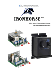
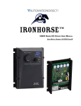
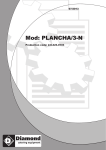
1
SIMATIC PCS 7 cabinet design
6/2
6/2
Introduction
Overview
6/3
6/4
6/5
Basic cabinet
ET 200M I/O unit
System unit
Siemens PLT 112 · 2002
6/1
SIMATIC PCS 7 cabinet design
Introduction
Cabinet packaging system
SIMATIC PCS 7 cabinet design
Modular design
System-specific modules
• AS 488/TM system unit
• ET 200M I/O unit (ET 200U/ET 200B on request)
System-neutral modules
• Basic cabinet, consisting of framework, door, outer walls, internal mechanical parts and power supply assembly with:
- Compartment for documents
- Trim
- AC 230 V socket
- AC 230 V or DC 24 V cabinet illumination
- I & C monitoring via automation system or cabinet lamp
Options
• Circuit-breaker for protection of max. 6 cabinet tiers
• I/O modules for ET 200M I/O unit
High flexibility
• Future compatibility as result of universal, system-neutral modules
• Modular packaging system permits flexible adaptation to the
respective application
• Basic and expansion cabinets based on the same set of modules
• Up to 4 system units or 6 I/O units can be fitted in a cabinet
• System units and I/O units can be combined within the cabinet
• Side walls or partitions can be selected specific to the application
• Cabinets can be screwed together into double units or rows
■ Overview
The cabinet design for components close to the process (automation systems and I/Os) fulfills the technical and economical
demands placed on the AS 488/TM automation systems.
The cabinets consisting of system-specific modules (system
and I/O units) and system-neutral modules (basic cabinets and
options) comply with CE requirements and conform to the guidelines for electromagnetic compatibility. They are designed according to the VGB 4 guidelines, and provide exceptional
protection against unauthorized interventions, mechanical effects, contamination and corrosion.
As a result of their variable modular design, the cabinets can be
readily adapted to different types of system (for batch processes
or continuous processes) and system sizes.
The Siemens standard cabinet 8MC with degree of protection
IP 40 is the preferred basic cabinet. Cabinets with degree of
protection IP 20 and IP 55 are alternatively available.
• Design supports installation, commissioning, servicing and repairs
• Design supports correct handling when replacing modules
• All installation, commissioning, servicing and repair work can
be carried out from the front of the cabinet
• Design of power supply assembly: either with Siemens circuitbreakers or with circuit-breakers with monitoring contact for
connection to receptacles (from company ETA)
• Wiring for electronics supply as well as load power supply to
I/O modules
• Wiring of PROFIBUS-DP either with copper or fiber-optic cables
Consideration of Ex(i)-specific requirements
• The construction of the system and I/O units permits a cabinet
design which satisfies the Ex(i)-specific requirements
• Uniform installation and replacement for all I/O modules from
the ET 200M range, including Ex(i) modules (plug connection
for load power supply above the modules).
Design guidelines
• The SIMATIC S7-300 and S7-400 design guidelines apply
when installing the AS 488 in PCS 7 cabinets (only with exclusively distributed SIMATIC I/Os).
Preparation of quotation, consulting and ordering
• Siemens AG
D-76187 Karlsruhe
Tel.: +49 721 595-3776
Fax: +49 721 595-4711
E-mail: [email protected]
6/2
Siemens PLT 112 · 2002
SIMATIC PCS 7 cabinet design
Basic cabinet
Electrical design
Each delivered cabinet contains:
• Power supply assembly AC 230 V or DC 24 V
• Cable clamps and screen bars for I/O and bus cables
• Prewiring of power supply cables for central and I/O units
• Wiring of PROFIBUS-DP fieldbus
• Connector board for cabinet earth
Options for the electrical design
• AC 230 V socket (installed in power supply assembly)
• I & C monitoring (2 versions):
- I & C monitoring via cabinet lamp. A blown fuse is signalled
by a lamp in the cabinet door. OLM failure can be additionally
displayed on the cabinet lamp
or
- I & C monitoring via AS 488/TM and cabinet lamp. Temperature violations in the cabinet, an open door contact, a blown
fuse and an OLM failure can be recorded by the IF 961-DIO
interface module and additionally signalled by a lamp in the
cabinet door
- Single/redundant design of power supply assembly, optionally with 6 or 14 circuit-breaker receptacles
■ Overview
The Siemens standard cabinet 8MC is the preferred basic cabinet. The Siemens standard cabinet 8MC is a sheet-steel cabinet
with rear panel and front door which can be assembled individually or also in rows with further cabinets of this type.
Side walls and partitions are optional, thus permitting variable
adaptation of the cabinet to different installation possibilities.
Up to four system units or six I/O units can be fitted in a cabinet
in conjunction with a DC 24 V or AC 230 V power supply assembly. System and I/O units can also be combined together within
a cabinet. The cables are introduced into the cabinet from below.
Mechanical design
Each delivered cabinet contains:
• Cabinet illumination
Preparation of quotation, consulting and ordering
Siemens AG
D-76187 Karlsruhe
Tel.: +49 721 595-3776
Fax: +49 721 595-4711
E-mail: [email protected]
■ Technical Specifications
Siemens standard cabinet
Dimensions (H x W x D) in mm
2000 x 800 x 400
Framework, completely welded
Sheet-steel, 2 mm,
frame profile with 10 edges,
cross-member profile with 5
edges
Rear panel
Sheet-steel, 1.5 mm, canted
Roof
Sheet-steel, 1.5 mm, canted
• 19-inch mounting frame
• Rear panel
• Door
• Transport lugs
Side wall (option)
Sheet-steel, 1.5 mm, canted
Partition (option)
Sheet-steel, 1.5 mm, canted
Single-leaf door on front of cabinet
with hinge on right
Sheet-steel, 1.5 mm,
opening angle approx. 180°;
including rod lock with 3 mm lock
insert and double-barb key
DIN 43 668
Degree of protection to EN 60 529
IP 40, with single installation or
together with cabinets of the
same type
Color
Ergo gray to
SN 30 920-C611-B13
• Trim
Permissible ambient temperature
Max. 40 °C
• Side walls/partitions: the basic cabinets are suitable for individual assembly or in rows. Therefore side walls and/or partitions
can be selected when ordering.
Permissible temperature inside
cabinet
Max. 55 °C
Permissible heat dissipation without fan
350 W, referred to maximum values of ambient temperature and
temperature inside cabinet
• Clips for routing of process cables
• Cable duct for cabinet-internal wiring
Options for the mechanical design
When ordering the basic cabinet, the following options are available for the mechanical design of the cabinet:
• Plinth: a cabinet plinth should be used if cables cannot be connected through the floor. The plinths are preassembled, and
available with a height of 100 or 200 mm
• Pocket for documents
Siemens PLT 112 · 2002
6/3
SIMATIC PCS 7 cabinet design
ET 200M I/O unit
Hot swapping
When ordering an ET 200M I/O station, it is additionally possible
to order the hot swapping function.
In an I & C system, it may be necessary to replace modules during operation for reasons of increased availability. The I/O subsystem for hot swapping is available for this as a version of the
ET 200M. This version permits replacement of modules without
having to switch off the associated ET 200M subsystem. The
functions of the inserted modules are not affected. The hot
swapping subsystem consists of backplane modules which can
be assembled to form a backplane of the required length, and a
matching mounting rail.
■ Overview
Complete ET 200M I/O stations are available for the cabinet
packaging system. The station includes the power supply, components for connection to the PROFIBUS-DP fieldbus (electrical
or optical design), selection of modules for hot swapping, and
wiring of load current connections.
The modular ET 200M I/O station with degree of protection IP 20
can be equipped with signal and function modules from the SIMATIC S7-300 automation system. These modules must be additionally ordered as required.
Power supply
The ET 200M I/O station can be operated with DC 24 V or
AC 120/230 V. With a DC 24 V supply, the I/O station is powered
directly from the cabinet’s power supply assembly, with an
AC 120/230 V supply, a PS 307 power supply module is additionally required upstream of the IM 153 interface module in the
I/O station in order to convert the AC 120/230 V into DC 24 V. The
DC 24 V input voltage provided by the power supply assembly
or the PS 307 power supply module is used to power the IM 153
and is the load power supply for the I/O modules.
The PS 307 power supply module is available in 5 A and 10 A
versions. The PS 307-1E version with a rated output current of
5 A is standard. If the configuration of the I/O station with
I/O modules results in a higher load, it is recommendable to use
the PS 307-1K with a rated output current of 10 A. Note, however, that the PS 307-1K width of 200 mm (compared to 80 mm
with the PS 307-1E) means that a maximum of six I/O modules
can be plugged onto the rail.
One fuse is fitted in the power supply assembly for each I/O station. With a DC 24 V supply, the IM 153 module and the L+/Mpower supply for I/O modules are fused together.
With an AC 120/230 V supply, the PS 307 power supply module
is fused. The L+/M voltage for the I/O modules is also obtained
from the PS 307.
6/4
Siemens PLT 112 · 2002
Special bus modules are required for the hot swapping function.
In addition to the PS/IM bus module for the IM 153-1, IM 153-2
and IM 153-3 modules, these are the bus module 2 x 40 for accommodation of two I/O modules with a width of 40 mm each
and the bus module 1 x 80 for accommodation of one module
with a width of 80 mm. Up to four bus modules for I/O modules
can be plugged onto each rail in addition to the PS/IM bus module. Bus module covers can be ordered separately for unused
I/O slots.
Ex(i) design
The cable duct with the Ex(i) version is designed as standard in
blue. Ex process cables are routed separately from other cables
in the cable duct. Furthermore, a mechanical separation is required between the IM 153 module and the first Ex I/O module.
An Ex partition is fitted for the hot swapping function to guarantee the specified insulation distance between intrinsically-safe
and non-intrinsically-safe areas of the ET 200M distributed I/Os.
The DM 370 spacer module is used for this purpose if the hot
swapping function is not required.
Load power supply for I/O modules
The load power supply for the I/O modules is connected via
plugs located above the I/O modules. One plug is provided for
each I/O module. The load power supplies are available in versions for four or eight I/O modules. With fewer than four or eight
I/O modules, the unused plug connectors are supplied separately should subsequent installation of I/O modules become
necessary.
Preparation of quotation, consulting and ordering
Siemens AG
D-76187 Karlsruhe
Tel.: +49 721 595-3776
Fax: +49 721 595-4711
E-mail: [email protected]
SIMATIC PCS 7 cabinet design
AS 488/TM system unit
• DC 24 V or AC 120/230 V power supply: depending on the input voltage, the AS 488/TM can be equipped either with a
PS 407 power supply module (AC 120/230 V supply) or a
PS 405 power supply module (DC 24 V supply), each rated at
10 A. These supply the AS 488/TM modules with the DC 5 V
and DC 24 V operating voltages via the backplane bus. The
PS 405 and PS 407 power supply modules also contain the
backup batteries for buffering the time and date.
• Supplementary system documentation consisting of a manual
for AS 388/TM, AS 488/TM and CS-L2 bridge in German or English.
■ Overview
The scope of delivery of the AS 488/TM is variable, and is defined specific to the order.
Fundamental components of the AS 488/TM are:
Preparation of quotation, consulting and ordering
Siemens AG
D-76187 Karlsruhe
• Mounting board for the UR2 rack and the rail for the OLM optical link module
Tel.: +49 721 595-3776
Fax: +49 721 595-4711
• AS 488/TM CPU, comprising:
- SIMATIC M7 CPU 486-3 or CPU 488-3
- Memory module set with 2 x 8 Mbyte
- UR2 rack (9 slots)
- IF 962-COM serial interface module for commissioning terminal with two RS 232 interfaces
- IF 961-DIO interface module for I & C monitoring functions
- AS 488/TM system software on 8-Mbyte memory card
- Commissioning terminal software on 3.5-inch diskette
E-mail: [email protected]
• PROFIBUS-DP connection for distributed I/Os via EXM 478 extension module, as electrical or optical design. The components for a second PROFIBUS-DP line must be ordered
separately.
• Components for connection to the CS 275 or PROFIBUS-TM
system bus, components for PROFIBUS-TM as electrical or optical design.
Siemens PLT 112 · 2002
6/5
SIMATIC PCS 7 cabinet design
6/6
Siemens PLT 112 · 2002