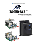
1
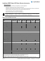
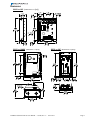
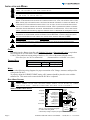
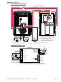
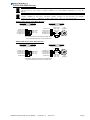
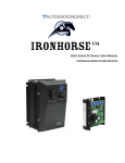
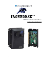
™
GSD1 Series DC Drives User Manual
User Manual Number: IH-GSD1-User-M
IronHorse GSD1 DC Drives User Manual – 1st Ed, Rev A – 12/12/2013
Page 1
~ WARNING ~
Thank you for purchasing automation equipment from Automationdirect.com®, doing business as AutomationDirect. We want your new automation equipment to operate safely. Anyone who installs or uses this equipment
should read this publication (and any other relevant publications) before installing or operating the equipment.
To minimize the risk of potential safety problems, you should follow all applicable local and national codes that
regulate the installation and operation of your equipment. These codes vary from area to area and usually change
with time. It is your responsibility to determine which codes should be followed, and to verify that the equipment,
installation, and operation is in compliance with the latest revision of these codes.
At a minimum, you should follow all applicable sections of the National Fire Code, National Electrical Code,
and the codes of the National Electrical Manufacturer’s Association (NEMA). There may be local regulatory or
government offices that can also help determine which codes and standards are necessary for safe installation and
operation.
Equipment damage or serious injury to personnel can result from the failure to follow all applicable codes
and standards. We do not guarantee the products described in this publication are suitable for your particular
application, nor do we assume any responsibility for your product design, installation, or operation.
Our products are not fault-tolerant and are not designed, manufactured or intended for use or resale as on-line
control equipment in hazardous environments requiring fail-safe performance, such as in the operation of
nuclear facilities, aircraft navigation or communication systems, air traffic control, direct life support machines,
or weapons systems, in which the failure of the product could lead directly to death, personal injury, or severe
physical or environmental damage (“High Risk Activities”). AutomationDirect specifically disclaims any
expressed or implied warranty of fitness for High Risk Activities.
For additional warranty and safety information, see the Terms and Conditions section of our catalog. If you have
any questions concerning the installation or operation of this equipment, or if you need additional information,
please call us at 770-844-4200.
This publication is based on information that was available at the time it was printed. At AutomationDirect we
constantly strive to improve our products and services, so we reserve the right to make changes to the products
and/or publications at any time without notice and without any obligation. This publication may also discuss
features that may not be available in certain revisions of the product.
Trademarks
This publication may contain references to products produced and/or offered by other companies. The product
and company names may be trademarked and are the sole property of their respective owners. AutomationDirect
disclaims any proprietary interest in the marks and names of others.
Copyright © 2013 Automationdirect.com® Incorporated
All Rights Reserved
No part of this manual shall be copied, reproduced, or transmitted in any way without the prior, written consent of
Automationdirect.com® Incorporated. AutomationDirect retains the exclusive rights to all information included
in this document.
Page 2
IronHorse GSD1 DC Drives User Manual – 1st Ed, Rev A – 12/12/2013
Contents
WARNING���������������������������������������������������������������������������������������������������������������������������������������������������������������������� 2
Trademarks���������������������������������������������������������������������������������������������������������������������������������������������������������������������� 2
GSD1 DC Drives User Manual Overview ����������������������������������������������������������������������������������������������������������������������� 3
IronHorse GSD1 Series DC Drives General Information����������������������������������������������������������������������������������������������� 4
Selection and Specifications ������������������������������������������������������������������������������������������������������������������������������������������� 4
Dimensions ���������������������������������������������������������������������������������������������������������������������������������������������������������������������� 5
Installation and Wiring���������������������������������������������������������������������������������������������������������������������������������������������������� 6
Trim Pot Adjustments ��������������������������������������������������������������������������������������������������������������������������������������������������� 10
Troubleshooting ����������������������������������������������������������������������������������������������������������������������������������������������������������� 10
GSD1 DC Drives User Manual Overview
Overview of this Publication
The IronHorse GSD1 Series DC Drives User Manual describes the installation, configuration, and
methods of operation of the GSD1 Series DC Drives.
All information contained in this manual is intended to be correct. However, information and data in this
manual are subject to change without notice. AutomationDirect (ADC) makes no warranty of any kind
with regard to this information or data. Further, ADC is not responsible for any omissions or errors or
consequential damage caused by the user of the product. ADC reserves the right to make manufacturing
changes which may not be included in this manual.
Who Should Read This User Manual
This manual contains important information for those who will install, maintain, and/or operate any of the
GSD1 Series DC Drives.
Technical Support
By Telephone: 770-844-4200 (Mon.–Fri., 9:00 a.m.–6:00 p.m. E.T.)
On the Web: www.automationdirect.com
Our technical support group is glad to work with you in answering your questions. If you cannot find
the solution to your particular application, or, if for any reason you need additional technical assistance,
please call Technical Support at 770-844-4200. We are available weekdays from 9:00 a.m. to 6:00 p.m.
Eastern Time.
We also encourage you to visit our web site where you can find technical and non-technical information
about our products and our company. Visit us at www.automationdirect.com.
Special Symbols
When you see the “notepad” icon in the left-hand margin, the paragraph to its
immediate right will be a special note.
When you see the “exclamation mark” icon in the left-hand margin, the paragraph to its immediate right
will be a WARNING. This information could prevent injury, loss of property, or even death (in extreme
cases).
IronHorse GSD1 DC Drives User Manual – 1st Ed, Rev A – 12/12/2013
Page 3
IronHorse GSD1 Series DC Drives General Information
Standard Features
• Provides smooth variable speed capability for mobile equipment.
• Maintains variable speed control as batteries discharge.
• Adjustable maximum speed, minimum speed, current limit, IR compensation, and motor acceleration.
• Inhibit terminal permits optional start-stop without breaking battery lines.
• Speed potentiometer, knob, and dialplate included.
• Enclosed model (GSD1-xx-10N4X) is rated NEMA 4X.
Carefully check the DC Drive for shipping damage. Report any damage to the
carrier immediately. Do not attempt to operate the drive if visible damage is
evident to either the circuit or to the electronic components.
Selection and Specifications
GSD1 Series DC Drives – Selection & Specifications
Model
Package Configuration
GSD1-12-10C
GSD1-1210N4X
GSD1-12-20C
GSD1-24-10C
GSD1-2410N4X
GSD1-24-20C
open frame
NEMA 4X
open frame
open frame
NEMA 4X
open frame
Power Quality Form Factor
1.05
Input Voltage **
12 VDC ±15%
Output Voltage
0–12 VDC
Motor Rating (hp)
1/50 – 1/8
Output Current (continuous)
10A (DC)
0 – (24–36) VDC
Current Overload Capacity
Current Limit
24–36 VDC ±15%
1/25 – 1/4
1/50 – 1/4
1/25 – 1/2
20A (DC)
10A (DC)
20A (DC)
200% for 10s; 150% for 60s
adjustable to 200% of motor Full Load Current (up to the Continuous Output Current rating of the drive)
Speed Adjustment
5kΩ or 0–10 VDC input signal
Speed Range
30:1
Speed Regulation
1% of base speed
Maximum Speed
adjustable from 50% to 100% of base speed
Minimum Speed
30% of adjustable maximum speed
Acceleration
adjustable from 0 to 10 seconds
Deceleration
0.5s (non-adjustable)
Dynamic Braking
no
Plugging Capability ***
Internal Operating Frequency
no
18 kHz
Electrical Connections
External Fusing Required
SCCR
approx 1.6 kHz
approx 1.6 kHz
barrier terminal block; accepts 12–6 AWG
DC-rated @ 150% motor Full Load Current (up to 150% Continuous Output Current rating of drive)
20A (DC)
40A (DC)
Operating Temperature
20A (DC)
40A (DC)
-10 to 45 °C [14 to 113 °F]
Thermal Protection
not available
Mounting Orientation
can be mounted in any orientation
Corrosive Gases
Weight
18 kHz
NOT compatible with any corrosive gases
6oz [170g]
37 oz [1049g]
10.5 oz [297g]
Agency Approvals
6oz [170g]
37 oz [1049g]
10.5 oz [297g]
RoHS
Optional Accessories *
Replacement Potentiometer
GSDA-5K
Digital Potentiometer
GSDA-DP
* For accessories details, please visit www.AutomationDirect.com.
** Input power supply must not exceed recommended voltage, or it may damage the GSD1 drive.
Linear power supply can be sized per drive voltage and motor full load current.
Switched power supply should be sized per drive voltage and double the motor full load current.
*** Plugging is a method of rapidly changing motor direction by reversing motor armature polarity, while the motor is still running.
Page 4
IronHorse GSD1 DC Drives User Manual – 1st Ed, Rev A – 12/12/2013
Dimensions
GSD1-xx-10C (dimensions = in [mm])
GSD1-xx-10N4X (dimensions = in [mm])
GSD1-xx-20C (dimensions = in [mm])
IronHorse GSD1 DC Drives User Manual – 1st Ed, Rev A – 12/12/2013
Page 5
Installation and Wiring
Install open-frame drives in an enclosure with a volume at least three
times the volume of the open-frame drive.
Do not mount controller where ambient temperature is outside the range
of -10 to 45 °C (14 to 113 °F).
Improper installation or operation of this DC Drive may cause injury to personnel or drive
failure. The drive must be installed in accordance with local, state, and national safety codes.
Make certain that the power supply is disconnected before attempting to service or remove any
components!!! If the power disconnect point is out of sight, lock it in disconnected position
and tag it to prevent unexpected application of power. Only a qualified electrician or service
personnel should perform any electrical troubleshooting or maintenance. At no time should
circuit continuity be checked by shorting terminals with a screwdriver or other metal device.
Before attempting to wire the DC Drive, make sure all power is disconnected. Recheck code
designation to assure proper voltage is present for the DC Drive. Caution should be used in
selecting proper wire size for current and voltage drop; minimum wire size 12 AWG.
Do not reverse positive and negative battery leads, as this will damage the DC Drive.
To change motor direction, interchange the positive and negative motor armature leads.
CAUTION!! Turn power OFF while making wiring connections.
Fusing
Externally fuse the +Battery input line with Littlefuse 314 series or Bussman ABC series or equivalent
fuses designed for use with motors and motor control systems; rated for the lesser of:
1) 200% of the continuous current rating of the drive, or 2) 150% of the motor full-load current.
(Fast-blow fuses are NOT recommended)
(AutomationDirect sells ABC series fuses.)
Terminal Block
GSD1 Wiring Terminals
Type
Wire Range
Tightening Torque
Barrier terminal block
12–6 AWG
4.4 lb·in [5.1 kg·cm]
Wiring
Refer to the following wiring diagrams for proper connection of DC Voltage, Armature, and Speed Pot
wiring to the DC drive.
To properly adjust the CURRENT LIMIT setting, a DC ammeter should be placed in series with the
armature line. This meter can be removed after the DC Drive is adjusted.
Basic Wiring Diagrams
Speed pots can be replaced by 0–10V analog signals (PLC, etc.). Connect
signal common to Pot Low; voltage signal source to Pot Wiper; no connection to Pot High. (Analog signal does not have to be isolated.)
GSD1-xx-10C Basic Wiring Diagram
Min Speed
Max Speed
Accel
I.R. Comp.
Current Limit
Inhibit (P1-9)
Common (P1-8)
Pot Low (P1-7)
Pot Wiper (P1-6)
Pot High (P1-5)
-Arm (P1-4)
+Arm (P1-3)
+Battery (P1-2)
-Battery (P1-1)
P1
GSD1-xx-10C
Page 6
5kΩ
Speedpot
Orange
Red
White
Motor
Customer
supplied
SPST switch
or relay
+
12/24/36
VDC**
Battery**
** Select battery voltage as required per application and model specifications.
* Refer to “Control Inhibit Wiring Diagrams”
for Control Inhibit wiring details.
Optional
Inhibit *
IronHorse GSD1 DC Drives User Manual – 1st Ed, Rev A – 12/12/2013
GSD1-xx-10N4X Basic Wiring Diagram
Factory prewiring
RED
RED
WHITE
GSD1-xx-10N4X – base
IR
Accel Max
Comp
RED
Min
-B
+B
+A
-A
HI
WP
LO
COM
INH
Cur
Lim
ORANGE
GSD1-xx-10N4X – front cover
Optional
Inhibit *
Battery**
-
+
+
Motor
* Refer to “Control Inhibit Wiring Diagrams”
for Control Inhibit wiring details.
** Select battery voltage as required per
application and model specifications.
-
12/24/36 VDC**
Customer wiring
GSD1-xx-20C Basic Wiring Diagram
5kΩ
Speedpot
GSD1-xx-20C
-Battery (P1-1)
+
Motor
-Arm (P1-2)
Battery
12/24/36
VDC**
White
Red
Orange
Optional
Inhibit *
Accel
+Battery (P1-4)
+Arm (P1-5)
P2
I.R. Comp.
No Connect (P1-3)
Customer supplied
SPST switch or relay
+
Caution:
Motor and battery wire must
be a minimum of 12 AWG
and a maximum of 6AWG.
Pot High (P2-1)
Pot Wiper (P2-2)
Pot Low (P2-3)
Common (P2-4)
Inhibit (P2-5)
Current Limit
Max Speed
Min Speed
P1
* Refer to “Control Inhibit Wiring Diagrams” for Control Inhibit wiring details.
** Select battery voltage as required per application and model specifications.
IronHorse GSD1 DC Drives User Manual – 1st Ed, Rev A – 12/12/2013
Page 7
Reversing Wiring Diagrams
Caution: When reversing a spinning permanent magnet DC motor, caution must be taken that
the resulting current through the armature of the motor does not exceed the overload ratings
of the
DC drive, or the demagnetize rating of the motor being reversed.
Caution: Ensure that motor rotation has stopped before reversing the applied voltage.
Speed pots can be replaced by 0–10V analog signals (PLC, etc.). Connect
signal common to Pot Low; voltage signal source to Pot Wiper; no connection to Pot High. (Analog signal does not have to be isolated.)
GSD1-xx-10C Reversing Wiring Diagram
Min Speed
Max Speed
Accel
I.R. Comp.
Current Limit
Inhibit (P1-9)
Common (P1-8)
Pot Low (P1-7)
Pot Wiper (P1-6)
Pot High (P1-5)
-Arm (P1-4)
+Arm (P1-3)
+Battery (P1-2)
-Battery (P1-1)
Optional
Inhibit *
P1
5kΩ
Speedpot
Orange
Red
Customer supplied
3PDT Center-off
Center-Blocked switch
(4PDT GSDA-MREV shown)
Motor
White
OFF
OFF
GSD1-xx-10C
12/24/36
VDC**
* Refer to “Control Inhibit Wiring Diagrams”
for Control Inhibit wiring details.
Customer
supplied
SPST switch or relay
+
Battery**
-
OFF
OFF
** Select battery voltage as required per
application and model specifications.
GSD1-xx-20C Reversing Wiring Diagram
Customer supplied
3PDT Center-off
Center-Blocked switch
(4PDT GSDA-MREV shown)
Motor
Relays may be used in place of switch, but a neutral position must be provided
to prevent plug reversing. Do not engage opposite direction until motor has
come to a complete stop. Failure to do so may result in damage to the control.
White
5kΩ
Speedpot
GSD1-xx-20C
OFF
OFF
OFF
OFF
-Battery (P1-1)
-
Battery**
12/24/36 VDC**
-Arm (P1-2)
+
+Battery (P1-4)
** Select battery voltage as required
per application and model specifications.
Page 8
+Arm (P1-5)
P2
Red
Orange
I.R. Comp.
No Connect (P1-3)
Customer supplied
SPST switch or relay
Caution:
Motor and battery wire must be a
minimum of 12 AWG and a maximum of 6AWG.
Pot High (P2-1)
Pot Wiper (P2-2)
Pot Low (P2-3)
Common (P2-4)
Inhibit (P2-5)
Optional
Inhibit *
Accel
Current
Limit
Max Speed
Min Speed
P1
* Refer to “Control Inhibit Wiring Diagrams” for Control Inhibit wiring details.
IronHorse GSD1 DC Drives User Manual – 1st Ed, Rev A – 12/12/2013
Control Inhibit Wiring Diagrams
Always use a shielded cable when connecting to the inhibit terminal.
The shield of the cable should connect to the Common terminal of the DC
Drive.
Speed pots can be replaced by 0–10V analog signals (PLC, etc.). Connect
signal common to Pot Low; voltage signal source to Pot Wiper; no connection to Pot High. (Analog signal does not have to be isolated.)
GSD1-xxx-10xxx Control Inhibit Wiring Diagrams
Control Inhibit by using Inhibit Input:
Provides fast Start-Stop
by bypassing accel/decel circuit
Inhibit* (P1-9)
Common (P1-8)
Pot Low (P1-7)
Pot Wiper (P1-6)
Pot High (P1-5)
SPST Switch
open = run
close = stop
Control Inhibit by using Speedpot:
Provides Start-Stop
using accel/decel settings
Inhibit* (P1-9)
Common (P1-8)
Pot Low (P1-7)
Pot Wiper (P1-6)
Pot High (P1-5)
SPST Switch
open = stop
close = run
Orange
Red
White
5kΩ
Speedpot
P1*
P1*
* Use shielded cable when connecting to the Inhibit terminal.
Connect the cable shield to the Common terminal of P1.
GSD1-xxx-20C Control Inhibit Wiring Diagrams
Control Inhibit by using Inhibit Input:
Provides fast Start-Stop
by bypassing accel/decel circuit
Pot High (P2-1)
Pot Wiper (P2-2)
Pot Low (P2-3)
Common (P2-4)
Inhibit* (P2-5)
SPST Switch
open = run
close = stop
Control Inhibit by using Speedpot:
Provides Start-Stop
using accel/decel settings
Pot High (P2-1)
Pot Wiper (P2-2)
Pot Low (P2-3)
Common (P2-4)
Inhibit* (P2-5)
P2*
P2*
* Use shielded cable when connecting to the Inhibit terminal.
Connect the cable shield to the Common terminal of P2.
White
Red
Orange
SPST Switch
open = stop
close = run
IronHorse GSD1 DC Drives User Manual – 1st Ed, Rev A – 12/12/2013
5kΩ
Speedpot
Page 9
Trim Pot Adjustments
Before the power is applied, the speed potentiometer and trim pots should be preset as follows:
TRIM POT PRESET
1) Preset Speed pot fully CCW.
2) Preset MAX trim pot CW 1/2 way.
3) Preset CURRENT LIMIT trim pot fully CW.
4) Preset MIN trim pot fully CCW.
5) Preset ACCEL trim pot CW 1/2 way.
6) Preset IR trim pot fully CCW.
DC power can now be applied to the system and the DC Drive adjusted as follows:
TRIM POT ADJUSTMENT
7) Increase the MIN trim pot CW until just before reaching an output voltage (deadband), or until the
desired minimum speed is reached.
8) Turn the Speed pot fully CW and adjust the MAX trim pot until the desired maximum speed is
reached.
9) Adjust the ACCEL trim pot to achieve the desired soft start time.
(CW rotation will increase accel time.)
10) Rotate the CURRENT LIMIT trim pot fully CCW. Apply a full load to the motor. While motor is
stalled, adjust the CURRENT LIMIT trim pot CW until a desired current setting is obtained.
(Approximately 125% of rated motor current is recommended.)
11) For 10A models GSD1-xx-10xxx:
Set the Speed pot to approximately 50%, and note the motor RPM. Load the motor to normal load
condition and adjust the IR trim pot CW until motor RPM is equal to the unloaded speed.
For 20A models GSD1-xx-20C:
Adjust the IR trim pot CW 1/2 way. If the motor speed is inconsistent (jumpy), rotate the IR trim pot
CCW until the motor rotation becomes stable.
Troubleshooting
If a newly installed DC Drive will not operate, it is likely that a terminal connection is loose. Check the
terminal connections and ensure that they are secure and correct. If the drive is still inoperative, refer to
the Troubleshooting Table.
Troubleshooting
Page 10
Problem
Possible Cause(s)
Corrective Action
Motor doesn’t run
1)
2)
3)
4)
1)
2)
3)
4)
Motor “hunts”
1) Max trim pot set too high
2) IR Comp trim pot set too high
1) Refer to “Trim Pot Adjustment”
2) Refer to “Trim Pot Adjustment”
Motor runs uncontrollably at “full
speed”
1) Loose Speed pot connections
2) Min or Max trim pots improperly adjusted
3) Possible drive failure
1) Secure all connections
2) Refer to “Trim Pot Adjustment
3) Contact ADC Technical Support
Motor rotates in wrong direction
Motor armature hooked up backwards
Reverse armature + and - leads
Motor stalls under a light load
Current Limit trim pot improperly adjusted
Refer to “Trim Pot Adjustment”
Incorrect or no power
Speed pot set at zero
Worn motor brushes
Current Limit set too low
Install proper power service
Rotate Speed pot fully CW
Replace motor brushes
Adjust Current Limit trim pot CW
IronHorse GSD1 DC Drives User Manual – 1st Ed, Rev A – 12/12/2013
BLANK
PAGE
IronHorse GSD1 DC Drives User Manual – 1st Ed, Rev A – 12/12/2013
Page 11
Literature Number: LT136
Drawing Number: A-5-3900A
Page 12
IronHorse GSD1 DC Drives User Manual – 1st Ed, Rev A – 12/12/2013