1
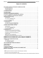
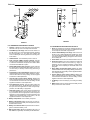
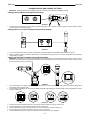
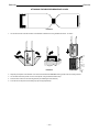
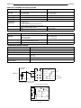
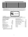
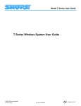
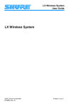
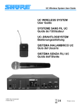
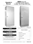
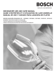
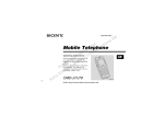
UP PORTABLE UHF Wireless System User Guide 2002, Shure Incorporated 27C8681 (Rev. 3) Patents 6, 296, 565; Des. 433, 642 Printed in U.S.A. ENGLISH ENGLISH TABLE OF CONTENTS QUICK SETUP GUIDE FOR THE SHURE UP WIRELESS SYSTEM . . . . . . . . . . . . . . . . . . . . . . . . . . . . . . . . . . UP4 RECEIVER SETUP . . . . . . . . . . . . . . . . . . . . . . . . . . . . . . . . . . . . . . . . . . . . . . . . . . . . . . . . . . . . . . . . . . . . . . TRANSMITTER SETUP . . . . . . . . . . . . . . . . . . . . . . . . . . . . . . . . . . . . . . . . . . . . . . . . . . . . . . . . . . . . . . . . . . . . . . SYSTEM OPERATION . . . . . . . . . . . . . . . . . . . . . . . . . . . . . . . . . . . . . . . . . . . . . . . . . . . . . . . . . . . . . . . . . . . . . . . 1 1 1 1 SYSTEM DESCRIPTION . . . . . . . . . . . . . . . . . . . . . . . . . . . . . . . . . . . . . . . . . . . . . . . . . . . . . . . . . . . . . . . . . . . . . . . . . 2 SYSTEM FEATURES . . . . . . . . . . . . . . . . . . . . . . . . . . . . . . . . . . . . . . . . . . . . . . . . . . . . . . . . . . . . . . . . . . . . . . . . . . . . 2 UP4 RECEIVER FEATURES AND CONTROLS . . . . . . . . . . . . . . . . . . . . . . . . . . . . . . . . . . . . . . . . . . . . . . . . . . . . 3 UC1 AND UC2 TRANSMITTER FEATURES AND CONTROLS . . . . . . . . . . . . . . . . . . . . . . . . . . . . . . . . . . . . . . . 4 U1 AND U2 TRANSMITTER FEATURES AND CONTROLS . . . . . . . . . . . . . . . . . . . . . . . . . . . . . . . . . . . . . . . . . . 5 CHECKING BATTERY STATUS . . . . . . . . . . . . . . . . . . . . . . . . . . . . . . . . . . . . . . . . . . . . . . . . . . . . . . . . . . . . . . . . . . UP4 RECEIVER . . . . . . . . . . . . . . . . . . . . . . . . . . . . . . . . . . . . . . . . . . . . . . . . . . . . . . . . . . . . . . . . . . . . . . . . . . . . . UC1 and UC2 TRANSMITTERS . . . . . . . . . . . . . . . . . . . . . . . . . . . . . . . . . . . . . . . . . . . . . . . . . . . . . . . . . . . . . . . U1 and U2 TRANSMITTERS . . . . . . . . . . . . . . . . . . . . . . . . . . . . . . . . . . . . . . . . . . . . . . . . . . . . . . . . . . . . . . . . . . 6 6 6 6 INSTALLING BATTERIES . . . . . . . . . . . . . . . . . . . . . . . . . . . . . . . . . . . . . . . . . . . . . . . . . . . . . . . . . . . . . . . . . . . . . . . . UP4 RECEIVER . . . . . . . . . . . . . . . . . . . . . . . . . . . . . . . . . . . . . . . . . . . . . . . . . . . . . . . . . . . . . . . . . . . . . . . . . . . . . UC1 AND U1 BODYPACK TRANSMITTERS . . . . . . . . . . . . . . . . . . . . . . . . . . . . . . . . . . . . . . . . . . . . . . . . . . . . . . UC2 AND U2 HANDHELD TRANSMITTERS . . . . . . . . . . . . . . . . . . . . . . . . . . . . . . . . . . . . . . . . . . . . . . . . . . . . . . 7 7 7 7 CHANGING GROUP/CHANNEL SETTINGS . . . . . . . . . . . . . . . . . . . . . . . . . . . . . . . . . . . . . . . . . . . . . . . . . . . . . . . . . UP4 RECEIVER . . . . . . . . . . . . . . . . . . . . . . . . . . . . . . . . . . . . . . . . . . . . . . . . . . . . . . . . . . . . . . . . . . . . . . . . . . . . . UC1 and UC2 TRANSMITTERS . . . . . . . . . . . . . . . . . . . . . . . . . . . . . . . . . . . . . . . . . . . . . . . . . . . . . . . . . . . . . . . U1 and U2 TRANSMITTERS . . . . . . . . . . . . . . . . . . . . . . . . . . . . . . . . . . . . . . . . . . . . . . . . . . . . . . . . . . . . . . . . . . 8 8 8 8 UP4 RECEIVER SET UP . . . . . . . . . . . . . . . . . . . . . . . . . . . . . . . . . . . . . . . . . . . . . . . . . . . . . . . . . . . . . . . . . . . . . . . . . ATTACHING THE UP4 RECEIVER ANTENNA . . . . . . . . . . . . . . . . . . . . . . . . . . . . . . . . . . . . . . . . . . . . . . . . . ATTACHING THE MOUNTING BOX TO CAMERA . . . . . . . . . . . . . . . . . . . . . . . . . . . . . . . . . . . . . . . . . . . . . . ATTACHING A SECOND MOUNTING BOX . . . . . . . . . . . . . . . . . . . . . . . . . . . . . . . . . . . . . . . . . . . . . . . . . . . . POWER CABLE . . . . . . . . . . . . . . . . . . . . . . . . . . . . . . . . . . . . . . . . . . . . . . . . . . . . . . . . . . . . . . . . . . . . . . . . . . . . INSTALLING THE UP4 RECEIVER . . . . . . . . . . . . . . . . . . . . . . . . . . . . . . . . . . . . . . . . . . . . . . . . . . . . . . . . . . . ATTACHING THE WEATHER-PROTECTIVE COVER . . . . . . . . . . . . . . . . . . . . . . . . . . . . . . . . . . . . . . . . . . . 10 10 10 10 11 12 12 OPERATING THE UP SYSTEM WITH THE U1 OR UC1 BODY-PACK TRANSMITTER . . . . . . . . . . . . . . . . . 13 OPERATING THE UP SYSTEM WITH THE U2 OR UC2 HAND-HELD TRANSMITTER . . . . . . . . . . . . . . . . . 13 CHANGING THE TRANSMITTER SETTINGS . . . . . . . . . . . . . . . . . . . . . . . . . . . . . . . . . . . . . . . . . . . . . . . . . . . . . GAIN LEVEL . . . . . . . . . . . . . . . . . . . . . . . . . . . . . . . . . . . . . . . . . . . . . . . . . . . . . . . . . . . . . . . . . . . . . . . . . . . . . . . UC1 ATTENUATOR SWITCH . . . . . . . . . . . . . . . . . . . . . . . . . . . . . . . . . . . . . . . . . . . . . . . . . . . . . . . . . . . . . . . . U1 ATTENUATOR SWITCH . . . . . . . . . . . . . . . . . . . . . . . . . . . . . . . . . . . . . . . . . . . . . . . . . . . . . . . . . . . . . . . . . . 14 14 14 14 TIPS FOR ACHIEVING OPTIMUM PERFORMANCE . . . . . . . . . . . . . . . . . . . . . . . . . . . . . . . . . . . . . . . . . . . . . . . 15 TROUBLESHOOTING . . . . . . . . . . . . . . . . . . . . . . . . . . . . . . . . . . . . . . . . . . . . . . . . . . . . . . . . . . . . . . . . . . . . . . . . . . 15 SPECIFICATIONS . . . . . . . . . . . . . . . . . . . . . . . . . . . . . . . . . . . . . . . . . . . . . . . . . . . . . . . . . . . . . . . . . . . . . . . . . . . . . 15 LICENSING INFORMATION . . . . . . . . . . . . . . . . . . . . . . . . . . . . . . . . . . . . . . . . . . . . . . . . . . . . . . . . . . . . . . . . . . . . . 17 FURNISHED AND OPTIONAL ACCESSORIES, REPLACEMENT PARTS . . . . . . . . . . . . . . . . . . . . . . . . . . . . . . . 17 WARRANTY INFORMATION . . . . . . . . . . . . . . . . . . . . . . . . . . . . . . . . . . . . . . . . . . . . . . . . . . . . . . . . . . . . . . . . . . . . 90 NOTE: Operation of this device is subject to the following two conditions: (1) this device may not cause interference, and (2) this device must accept interference, including interference that may cause undesired operation of the device. ENGLISH ENGLISH QUICK SETUP GUIDE FOR THE SHURE UP WIRELESS SYSTEM UP4 Receiver Setup and Camera Mounting To audio input To power supply (If not using interior battery power) ATTACHING THE MOUNTING BOX, INSTALLING THE UP4 RECEIVER FIGURE 1 1. Open the battery compartment on the UP4 receiver and insert a fresh 9 volt battery if battery power is to be used. Attach the two antennas to the ANTENNA IN SMA connectors. 2. Attach the mounting box to the video camera (see Attaching the Mounting Box to a Camera). 3. Insert the UP4 receiver into the mounted box. Connect the audio cable from the UP4 audio output into the audio input(s) of the video camera. If not using the receiver’s battery, attach a cable from the receiver’s dc jack to the camera’s battery port. (See Installing the UP4 Receiver) 4. Set the Push-Lock Audio Gain Pot to the appropriate level for the camera sound input or other equipment you are using. 5. Move the receiver’s power switch to the ON position. Note: If you encounter RF interference, change the Group and Channel setting on the transmitter and the receiver. Refer to the supplement for additional frequency information. UC1/UC2/U1/U2 Transmitter Setup 1. Open the battery cover and insert a fresh 9V alkaline battery (UC1/UC2) or two 1.5V AA batteries (U1/U2) 2. Make sure the transmitter Group and Channel settings match those of the receiver. If they do not, adjust settings using either a screwdriver (UC1 and UC2) or the electronic controls (U1 and U2). 3. Close the battery cover. System Operation 1. Turn the transmitter on and speak into the microphone. 2. On the UP4 receiver, the PWR LED, RF LED and AUD LED should illuminate green, indicating that the receiver is receiving the transmitter signal. 3. If the AUD LED on the receiver glows red steadily when you are speaking in a normal voice, try adjusting the transmitter gain until the AUD LED glows green on the receiver. The AUD LED should flash red when you speak loudly. –1– ENGLISH UC1 ENGLISH U2 UC2 U1 UP4 UP WIRELESS SYSTEM COMPONENTS FIGURE 2 SYSTEM DESCRIPTION The Shure UP Wireless System is a portable, frequency-agile, diversity wireless system operating in the UHF band. The UP4 receiver is easily mounted to a SonyR video camera or any video camera with an Anton-BauerR battery pack. The UP4 is compatible with both Shure UC and UHF Series microphones and body-packs. Both the receiver and the transmitter are microprocessor controlled by Phase Locked Loop (PLL) circuitry for a clear, steady signal. The following components are available with the UP system: UP4 Diversity Receiver with internal battery power supply, antennas, and camera-mounting hardware. UC1 or U1 Body-Pack Transmitter with your choice of a WL93, WL184, or WL185 lavalier microphone. UC2 or U2 Hand-Held Microphone-Transmitter with your choice of interchangeable microphone heads, including: • SM58 cardioid dynamic microphone • SM87 supercardioid condenser microphone SYSTEM FEATURES • UHF Band Operation. The Shure UP System operates within the UHF frequency band, which is less congested in metropolitan areas than the VHF band. Typically, UHF systems encounter less interference than VHF systems. • Frequency Agility. The UC and UHF-system transmitters’ and UP receiver’s frequencies can be changed to avoid RF interference. This ensures interference-free operation, even in the most congested RF environments. • Camera-Mountable Receiver Design. The UP4 receiver’s compact design allows easy mounting to Sony cameras and cameras outfitted with Anton-Bauer battery packs. The UP4 receiver is supplied with hardware for mounting to cameras. • Tone Key Squelch Circuitry. This circuitry prevents unwanted noise from entering the system, including the “pop” noise that occurs when the transmitter is turned on or off. • Noise Squelch Circuitry. This circuitry analyzes signal quality rather than signal strength, virtually eliminating the possibility of annoying noise bursts. • LED Indicators (On Receiver). Three LEDs provide information on audio level, RF level and battery power. –2– ENGLISH ENGLISH 9 8 6 7 10 1 2 3 4 11 UP4 RECEIVER CONTROLS AND INDICATORS 5 FIGURE 3 UP4 RECEIVER FEATURES 1. Group Setting Control. Rotate this switch clockwise to advance the Group setting, or rotate it counterclockwise to decrease the setting. Use the supplied screwdriver to make adjustments. 2. Channel Setting Control. Rotate this switch clockwise to advance the Channel setting, or rotate it counterclockwise to decrease the setting. Use the supplied screwdriver to make adjustments. 3. Three-way Power Switch. The power switch features three positions: ON (power on with tone key activated, to find the signal from Shure U or UC transmitter); OFF (power off); or ON (TONE KEY OFF) (power on with tone key disabled, to listen to interfering signals.) 4. Headphone Jack: This allows the user to listen to incoming audio signal. Accepts mono or stereo 1/8” plug. 5. Headphone Gain Control: This allows the user to set the headphone gain level at High, Mid-point or Low level, independent of audio level. 6. Push-Lock Audio Gain Pot: The audio gain pot recesses after the gain is set. Simply set to desired level and then push in to lock. Pot has a center detent at -40 dBu. (Consult your camera’s product literature for information on the proper level setting for the camera’s audio input.) 7. LED Indicators: Three LEDs provide information on the following functions: LED STATUS LED INDICATOR GREEN RED OFF RF Tone Key active, usable RF signal N/A No RF and/or no Tone Key AUD Audio at useable, non–peak level Audio within 9 dB of reaching peak (clip) level No audio/Low audio level PWR Power on Power on, receiver battery low Power off 8. 9. 10. 11. SMA Antenna Input Connectors. SMA–type connectors allow easy installation of the supplied antennas. Battery Compartment: Installation of a 9V battery allows use of unit without external power source. XLR Output Connector (Low Z). XLR connector provides balanced low-impedance output. Locking DC Jack: The DC jack allows powering of the receiver with an external DC source or an AC adaptor. The jack is threaded to insure a secure connection. –3– ENGLISH ENGLISH 1 2 3 4 1 1 2 2 3 3 4 4 5 6 5 6 8 7 9 7 8 10 11 12 FIGURE 5 FIGURE 4 UC1 TRANSMITTER FEATURES AND CONTROLS UC2 TRANSMITTER FEATURES AND CONTROLS 1. Antenna. A flexible 1/4 wave whip antenna is permanently attached to the top of the UC1 Body-Pack transmitter. 1. Grille. This protects the microphone cartridge and helps reduce breath sounds and wind noise. The grilles for the various microphone heads differ in appearance. 2. Power/Battery Fuel Gauge. When the Power switch is in the ON position, one of the three LEDs will glow, indicating that the transmitter is on. The LED color indicates the amount of battery life remaining. Refer to the Checking Batteries section. 2. Power Indicator/Battery Fuel Gauge. When the UC2 is turned on, one of three LEDs will glow, indicating that power is on and the amount of battery life remaining. Refer to the “Checking Transmitter Battery” paragraph for more information on battery life. 3. ON/OFF Switch. Turns transmitter power on and off. 3. Power Switch. This switch turns the transmitter on and off. 4. Input Connector (LEMO connector optional). This Mini connector (TA4F ) provides connection with a variety of lavalier, instrument and headset microphones and cables. LEMO connectors are available as an option. 4. Audio Gain Control. This control changes the audio level to accommodate various sound sources (e.g. singing or speaking). Use the supplied screwdriver to make adjustments. Refer to the “Adjusting the Transmitter Gain Level” paragraph. 5. Remote Mute Switch Input Connector. When used with the optional Shure UA101 Remote Mute Switch, this 3.5 mm connector lets you remotely mute the body pack during a performance. 5. Group Setting Control (Red Switch). Rotating this switch clockwise advances the Group setting. Rotating it counterclockwise decreases the Group setting. Use the supplied screwdriver to change the setting. 6. Group Setting Control (Red Switch). Rotating this switch clockwise advances the Group setting. Rotating it counterclockwise decreases the Group setting. Use the supplied screwdriver to make adjustments. 6. Channel Setting Control (Green Switch). Rotating this switch clockwise advances the Channel setting. Rotating it counterclockwise decreases the Channel setting. Use the supplied screwdriver to make adjustments. 7. Channel Setting Control (Green Switch). Rotating this switch clockwise advances the Channel setting. Rotating it counterclockwise decreases the Channel setting. Use the supplied screwdriver to make adjustments. 7. 9 V Battery. Access the battery by unscrewing the battery cover. 8. Battery Cover. Unscrew this to expose the battery and the Group, Channel and Gain controls. 8. Input Attenuation Control. This two position switch lets you select either 0 dB or –20 dB attenuation, depending on the input source and application. For most microphone applications, the 0 dB setting is appropriate. 9. Audio Gain Control. This control changes the audio level to accommodate different sound sources. The factory setting is at mid level, which is appropriate for most microphone applications, except headphone microphones (Refer to the “Adjusting the Transmitter Gain Level” section). Use the supplied screwdriver to make adjustments. 10. Battery Compartment. One 9V battery is required. 11. Battery Compartment Cover. Hinged cover on front surface opens to expose the battery and Group/Channel, Gain, and Attenuation controls. 12. Battery Cover Release Tabs. Squeeze these two tabs together to release the battery cover. 13. Belt Clip (not shown). Allows the transmitter to be worn on a belt, waistband, or guitar strap. The belt clip can be rotated 180°. –4– ENGLISH ENGLISH 1 1 3 4 5 1 2 2 7 8 ON OFF 9 6 3 10 GAIN 4 7 8 9 5 10 11 12 13 ON OFF 6 FIGURE 7 FIGURE 6 U2 TRANSMITTER CONTROLS & INDICATORS U1 TRANSMITTER CONTROLS & INDICATORS 1. Antenna. A 1/4 wave antenna is permanently attached to the top of the U1 body-pack transmitter. The antenna can be replaced in the field by a qualified technician. 2. Programmable Display. This display provides information on group and channel settings, battery power level, and frequency lock/power lock on/off status. 3. Input Connector. This connector functions with a variety of lavalier and headset microphone cables, and the Shure WA302 instrument adapter cable. LEMO–type connectors are available as an option. 4. ON/OFF Switch. This switch turns transmitter power on and off. 5. On/Off LED. When the U1 is turned on, this glows green. 6. Belt Clip. This allows the transmitter to be easily worn on a belt, waistband or guitar strap. 7. MODE Button. This button allows you to chose between changing the Group or the Channel setting. 8. SET Button. This button changes transmitter Group and Channel settings. Also used with the MODE button to lock power on and to lock the frequency and channel setting. 9. Audio Gain Control. This allows audio level adjustment to accommodate a variety of sound sources (speaking, singing, or playing an instrument). A small screwdriver is supplied for making adjustments. 10. Battery Cover Release Tabs. Squeeze these two tabs together to release the battery cover. 11. Battery Compartment Cover. Hinged cover on front surface opens to expose the battery and display control keys. 12. Battery Fuel Gauge. This meter visually indicates battery power level. 13. Battery Compartment. Two 1.5V AA batteries are required. (DuracellR MN1500 recommended). 1. Grille. The grille protects the microphone cartridge and helps reduce breath sounds and wind noise. The grilles for the various microphone heads differ in appearance. 2. Programmable Display. This display provides information on the Group and Channel settings, battery power level, and frequency lock/power lock on/off status. 3. Battery Fuel Gage. This meter visually indicates battery power level. 4. Battery Cover. Unscrew this to expose batteries and display control keys. 5. ON/OFF Switch. This switch turns transmitter power on and off. 6. Antenna. Helical antenna is attached to the end of the U2 transmitter. The antenna can be replaced in the field by a qualified technician. 7. Battery Compartment. Two 1.5 V AA batteries are required. 8. MODE Button. This button allows you to chose between changing the Group or the Channel setting. 9. SET Button. Changes transmitter Group and Channel settings. Also used with the MODE button to lock power on and to lock the frequency and channel setting. 10. Audio Gain Control. This allows audio level adjustment to accommodate a variety of sound sources (speaking, singing, or playing an instrument). A small screwdriver is supplied for making adjustments. –5– ENGLISH ENGLISH CHECKING BATTERIES UP4 Receiver 1. Turn the receiver power ON/OFF switch to the ON position. 2. Observe the PWR LED on front panel (See figure 8). If it is glowing red, the battery power is low and the battery should be changed immediately. PWR LED (Red Indicates Low Receiver Battery) FIGURE 8 UC1 and UC2 Transmitter 1. Turn the transmitter ON/OFF switch to the ON position. 2. Observe the three LED battery gauge (figure 9). Verify that one LED is glowing. The amount of battery life remaining is indicated by which LED is lit, as shown in the table below: Battery Gauge FIGURE 9 Transmitter LED Color Remaining Transmitter Operating Time Green 2 to 8 hours Amber 45 minutes to 2 hours Red 45 minutes or less U1 and U2 Transmitter 1. Turn the transmitter power ON/OFF switch to the ON position. 2. Observe the battery fuel gauge displayed on the transmitter screen. Battery power level is indicated by the number of black segments displayed. As transmitter batteries are consumed, the displayed segments will gradually disappear. NOTE: The dc to dc converter keeps the system voltage constant as battery voltage declines, ensuring superior audio and RF performance. Number of Segments Displayed on Transmitter 5 4 3 2 1 TRANSMITTER BATTERY FUEL GAUGE (ON TRANSMITTER DISPLAY) A Operating Time Remaining (in Hours)* 8 – 12 6–8 4–6 2–4 1 or less *Using Duracell MN1500 alkaline batteries. FIGURE 10 –6– B ENGLISH ENGLISH INSTALLING BATTERIES UP4 Receiver Á FIGURE 11 1. Locate the battery door on the bottom of the unit. Release the battery door by sliding the door in the direction of the arrow until the pins on either side of the door are visible. Flip open the battery door once it is released. 2. Insert a fresh 9 volt battery, with terminals facing down, observing the proper polarity (+/–). 3. Return the battery door to its original position and slide the pins back into the lock position. NOTE: The battery door can be opened when the UP4 receiver is mounted on a camera, allowing the battery to be replaced without dismounting the unit. If two receivers are mounted on the same camera, the top receiver and box will need to be dismounted in order to open the battery door on the bottom unit. UC1 or U1 Body-Pack Transmitter U1 UC1 1.5V AA 1.5V AA FIGURE 12 1. Make sure the transmitter power ON/OFF switch is in the OFF position. 2. Open the transmitter battery compartment by squeezing the two tabs on either side of the transmitter. Then flip the battery cover down. Refer to Figure 12. 3. To remove battery: UC1: Lift up on the edge of the battery remove it. U1: Press down on negative terminal end of each battery. 4. Insert a new 9V battery (UC1) or two fresh 1.5V AA batteries (U1) in the compartment. Maintain proper battery polarity (”+/–”). UC2 or U2 Hand–Held Transmitter U2 UC2 FIGURE 13 1. 2. 3. 4. Make sure the transmitter power ON/OFF switch is in the OFF position. Unscrew the battery cover. On the U2, Slide the cover down once it has been unscrewed. Pull down on the old battery and remove it (UC2) or lift the batteries out (U2). Install a fresh 9V alkaline battery (UC2) or two fresh 1.5 V AA batteries (U2). Maintain proper battery polarity (”+/–”). Screw the battery cover back into place. –7– ENGLISH ENGLISH CHANGING GROUP AND CHANNEL SETTINGS IMPORTANT: Transmitter GROUP and CHANNEL settings must match receiver GROUP and CHANNEL settings. Changing the UP4 Receiver Group/Channel Setting GROUP CHANNEL FIGURE 14 1. To advance the receiver Group or Channel setting, rotate the appropriate switch clockwise, using the supplied screwdriver. Rotate the switch counterclockwise to decrease the setting. Changing the UC1 or UC2 Transmitter Group/Channel Settings FIGURE 15 1. Turn the transmitter off and open the battery compartment to expose the GROUP and CHANNEL switches. Refer to Figure15. 2. Using the supplied screwdriver, rotate the GROUP switch until the desired setting is reached. Then rotate the CHANNEL switch until the the desired setting is reached. Changing U1 AND U2 Transmitter Group/Channel Settings IMPORTANT: Due to differences in design, there are variations in the preset group/channel settings between the UP4 receiver and the U1 and U2 transmitters. Consult the frequency supplement provided with these units to determine which U1/U2 Group/Channel setting corresponds to the UP4 Group/Channel setting you have chosen. B A FIGURE 16 C 1. Turn the transmitter on by sliding the transmitter power ON/OFF switch to the ON position. The existing Group and Channel settings will be automatically displayed (Figure 16A) . 2. Open the battery compartment. This will expose the MODE (left) and SET (right) buttons, as well as the GAIN control and the batteries, as shown in Figure 16 B and 16C. 3. 4. 5. 6. 7. FIGURE 17 B A D C Press and hold down the MODE button until only the Group number is displayed, as shown in Figure 17A. Press the SET button to change the Group setting, as shown in Figure 17B. Press the MODE button again so that only the Channel number is displayed, as shown in Figure 17C. Press the SET button to change the Channel setting, as shown in Figure 17D Press the MODE button again so that the new Group and Channel numbers are both displayed. –8– ENGLISH ENGLISH LOCKING THE POWER ON (U1 AND U2) B A FIGURE 18 1. To lock the power on, press and hold the SET button, then press and hold the MODE button. Hold both keys down until “PoL” (for power locked) is displayed, as shown in Figure 18A. NOTE: When the Power On Lock function is activated, “–– ––” will flash on the transmitter screen every 5 seconds when the transmitter power ON/OFF switch is in the OFF position. 2. To cancel the Transmitter Power On Lock function, press and hold the SET button, then press and hold the MODE button. Keep both keys pressed down until “Po UL” (for power unlocked) is displayed momentarily, as shown in Figure 17B. The Transmitter Power On Lock function can also be canceled by removing the batteries. ACTIVATING THE FREQUENCY LOCK FUNCTION (U1 AND U2) A B C FIGURE 19 The Frequency Lock function prevents accidental frequency changes, and is particularly useful in preventing accidental or unauthorized changes. The lock function is retained in memory, even if the transmitter is turned off and the batteries removed. To activate the Frequency Lock function, proceed as follows: 1. Turn the transmitter power off. 2. Turn the power back on while holding down the SET button until the fuel gauge on the transmitter is active. 3. “Fr L” will appear momentarily, as shown in Figure19A, until you release the SET button. 4. To verify that the frequency lock function is turned on, press the MODE or SET button. If the lock function is turned on, “– –” will appear on the transmitter screen, as shown in Figure 19B. NOTE: When the Frequency Lock function is engaged, the Power On Lock function can still be activated. However, if the Power Lock and the Frequency Lock functions are engaged, the Power Lock function must be disengaged before the Frequency Lock can be cancelled. 5. To cancel the Frequency Change Lock function, repeat steps 1 and 2 above. When the frequency lock function is turned off, Fr UL will appear on the transmitter display, as shown in Figure 19C. –9– ENGLISH ENGLISH UP4 RECEIVER SET UP Attaching The UP4 Receiver Antennas FIGURE 20 1. Center the antenna over the SMA Antenna Input Connectors on the front panel of the receiver. 2. Rotate the antenna in a clockwise direction until the base of the antenna is threaded firmly to the connector. Attaching the Mounting Box to a Camera A FIGURE 21 1. Locate the battery pack (A) on the camera. If it is a Sony or Anton Bauer equipped camera, there will be four mounting screws on the surface of the battery pack, either on the side or back of the battery pack. 2. Attach the mounting box by inserting the mounting screws in the large ends of the four mounting holes on the box. Lock the box to the battery pack by moving the box down so that the screws are in the small ends of the mounting holes. 3. Tighten the screws by inserting a screw driver into the access holes on the outside surface of the mounting box. Attaching a Second Mounting Box FIGURE 22 In some applications, it may be desirable to have two active receivers attached to the camera. In these cases, a second receiver can be “stacked” on the first receiver. To attach a second mounting box to a camera, follow these steps: 1. Insert supplied screws into the four screw holes of the mounted box. Engage the screw, but do not tighten; leave a space between the head of the screw and the surface of the mounting box. 2. Following steps 2 and 3 of Attaching a Mounting Box, using the mounting screws on the outside of the first box instead of the mounting screws on the battery pack. 3. Install the receiver as directed in Installing the UP4 Receiver. – 10 – ENGLISH ENGLISH INSTALLING THE UP4 RECEIVER Side Mounted Rear Mounted To Power Supply (if not using battery power) To Audio Input FIGURE 23 1. After the mounting box is attached to the camera, insert the UP receiver in the box. It should slide in easily, but fit snuggly. 2. Connect XLR audio output on the bottom of UP receiver to audio input on the camera. 3. If not using internal 9V battery power, connect the DC jack on the bottom of the UP receiver to an external power supply (see Power Cable). POWER CABLE The supplied power cable consists of a locking DC power jack on one end and bare wires on the other. This is due to the wide variety of connectors used by various camera manufacturers. In order to use the supplied power cable, you will first need to determine the appropriate connector for your camera. Once you have obtained the correct connector, you will need to attach it to the supplied power cable. For further information about this procedure, please contact Shure at 847/866–2200 and ask for the applications department. An AC power adaptor may also be used to power the UP4 from a wall socket or other AC power supply. – 11 – ENGLISH ENGLISH ATTACHING THE WEATHER-RESISTANT COVER FIGURE 24 1. Join the narrow ends of the two sections of the weather–resistant cover using the attached VelcroR as shown. FIGURE 25 2. Wrap the joined pieces of the weather cover around the UP4 Receiver BEFORE inserting the UP4 into its mounting bracket. 3. Join the wide ends of the pieces over the control panels, using the attached Velcro strips. 4. Insert the UP4 receiver into the mounting bracket (see Installing the UP4 Receiver). 5. To access the control panel or the battery, flip open the appropriate flap. – 12 – ENGLISH ENGLISH OPERATING THE UP SYSTEM WITH UC1 OR U1 BODY–PACK 1. If the UP4 receiver has not been mounted to the camera, attach the mounting box (See Attaching Mounting Box) and install the UP4 receiver, connecting the XLR output on the receiver to the sound input on the camera (See Installing UP4 Receiver). Set the Push-Lock Audio Gain Pot to the appropriate level for the camera sound input or other equipment you are using. If internal 9V battery power is not being used, attach the locking dc jack to an external dc source. 2. Clip the body-pack transmitter to your belt or waistband. 3. Connect the lavalier microphone or headset microphone the transmitter. NOTE: If you are using a headset microphone, the audio gain of the transmitter may need to be adjusted. See ADJUSTING THE AUDIO GAIN section for details. 4. Clip the lavalier microphone to your tie, lapel, or other garment. For best results, the microphone should be 15 to 20 cm (6 to 8 in.) below your chin. 5. Slide the transmitter ON/OFF switch to the ON position. Check battery status (see Checking Battery Status). 6. On the UP4 receiver, move the power switch to the ON position. The receiver PWR LED should glow green. If you are using internal 9V battery power and the PWR LED glows red, change the battery. 7. Make sure the transmitter and receiver are tuned to the same Group and Channel. If necessary, change the settings on either the transmitter or receiver. See Changing Group/Channel Settings. 8. Begin speaking. The RF and AUD LEDs on the receiver should glow green, with the AUD LED flashing red at the loudest sounds. NOTE: If the AUD LED on the receiver does not flicker red during the loudest sounds, or if it is consistently red, the transmitter gain may need to be increased or decreased. Refer to the Adjusting the Transmitter Gain Level section. If the system still does not operate properly, consult the Troubleshooting table included in this manual. 9. When the shoot is over, slide the transmitter and receiver ON/OFF switches to the OFF position to conserve battery power. LAVALIER MIC OPERATING THE BODY–PACK SYSTEM FIGURE 26 OPERATING THE UP SYSTEM WITH A UC2 OR U2 HAND-HELD TRANSMITTER 1. If the UP4 receiver has not been mounted to the camera, attach the mounting box (See Attaching Mounting Box) and install the UP4 receiver, connecting the XLR output on the receiver to the sound input on the camera (See Installing UP4 Receiver). Set the Push-Lock Audio Gain Pot to the appropriate level for the camera sound input or other equipment you are using. If internal 9V battery power is not being used, attach the locking dc jack to an external dc source. 2. Slide the transmitter power ON/OFF switch to the ON position. Check battery status (see Checking Battery Status). 3. On the UP4 receiver, move the power switch to the ON position. The receiver PWR LED should glow green. If you are using internal 9V battery power and the PWR LED glows red, change the battery. 4. Make sure the transmitter and receiver are tuned to the same Group and Channel. If necessary, change the settings on either the transmitter or receiver. See Changing Group/Channel Settings. 5. Begin speaking. The RF and AUD LEDs on the receiver should glow green, with the AUD LED flashing red at the loudest sounds. NOTE: If the AUD LED on the receiver does not flicker red during the loudest sounds, or if it is consistently red, the transmitter gain may need to be increased or decreased. Refer to the Adjusting the Transmitter Gain Level section. If the system still does not operate properly, consult the “Troubleshooting” table included in this manual. 6. When the shoot is over, slide the transmitter and receiver ON/OFF switches to the OFF position to conserve battery power. OPERATING THE HAND–HELD SYSTEM FIGURE 27 – 13 – ENGLISH ENGLISH CHANGING THE TRANSMITTER SETTINGS Adjusting the Transmitter Gain Level The U1, U2, UC1 and UC2 transmitter audio gain level has been factory preset to provide satisfactory output in most applications, and it will probably not need to be adjusted for most microphone applications. However, for loud talkers, the preset level may be too high, as indicated by a constant glow of the red audio LED on the receiver. Soft spoken talkers may find that the factory setting is too low, as indicated by the failure of the green audio level LED on the receiver to glow at all. To adjust audio gain, open the battery compartment and locate the transmitter audio gain control. Use the supplied screwdriver to make adjustments. See Figure 28. For high sound pressure level applications, such as loud speaking, decrease audio gain level by rotating the gain control counterclockwise (while the microphone is in use) until the red audio level LED on the receiver flickers only during the loudest sounds. For low sound pressure level applications, such as soft speaking, increase audio gain level by rotating the gain control clockwise until the red audio level LED on the receiver flickers only during the loudest sounds. DECREASE GAIN DECREASE GAIN DECREASE GAIN INCREASE GAIN INCREASE GAIN INCREASE GAIN Á DECREASE GAIN INCREASE GAIN ADJUSTING THE TRANSMITTER GAIN LEVEL FIGURE 28 UC1 Attenuator Switch The UC1 Transmitter features an attenuator switch inside the battery cover. For most situations, the 0 dB setting is preferable. The –20 dB setting was designed for use with high output musical instruments 0 –20 ATTENUATOR SWITCH THE UC1 TRANSMITTER ATTENUATION SWITCH FIGURE 29 U1 Attenuator Switch The U1 body-pack transmitter features an attenuator switch which may be adjusted through an access hole located beneath the transmitter’s belt clip. It is factory preset at –6 dB (center), which is the proper setting for most microphone applications, with the exception of low-output microphones such as a headset. For those applications, the attenuator switch should be set at 0dB (fully counterclockwise). The –20 dB (clockwise) position is designed for high output musical instruments. To remove the beltclip and gain access to the attenuator, carefully remove the wire bracket, one side at a time, from the side of the transmitter. To reinsert the belt clip, orient the clip so that the SHURE logo is on the outside toward the top (antenna side) of the transmitter. Carefully reinsert the clip’s wire bracket, one side at a time, into the body of the transmitter. Attenuator access Increase input level Decrease input level Clip sockets FIGURE 30 – 14 – ENGLISH ENGLISH TIPS FOR ACHIEVING OPTIMUM PERFORMANCE • Maintain a line of sight between the transmitter and receiver antennas. • Use the proper receiver antennas. • Do not obstruct the receiver antennas. • Avoid operating near metal objects. • Never use two transmitters set to the same frequency concurrently. • Keep distance between transmitter and receiver as short as possible. • Monitor the UP4’s PWR LED; if the PWR LED goes into low battery mode (red light) replace old battery with a fresh battery immediately. • For added protection, replace batteries before each shoot. TROUBLESHOOTING Some common problems and their solutions are identified in the table below. If you are unable to solve a problem, contact your dealer or the Shure Service Department at 1-800-516-2525 (7:30 am to 4:00 pm, Central Standard Time). In Europe, call 49-7131-72140; other international users call Shure in the U.S.A. at 847-866-2200. Problem Solution No sound; receiver RF LED and Make sure transmitter and receiver are turned on. AUD LEDs not glowing. Check transmitter Power/Battery Gauge. Replace battery if necessary. Make sure transmitter and receiver frequency Group/Channel settings are identical. Check receiver antenna connection(s). Make sure an antenna is in the line of sight of the transmitter. If necessary, reduce the distance between transmitter and receiver. No receiver sound; RF and AUD LEDs Check for proper connection between receiver and camera. glowing. Talk into the microphone and observe the receiver AUD LED. If it glows, the problem is elsewhere in the sound system. Check output gain setting Received signal is noisy or contains ex- Check transmitter Power/Battery Fuel Gauge and replace battery if power is low. traneous sounds with transmitter on. Remove local sources of RF interference, such as lighting equipment. Two transmitters may be operating on the same frequency. Locate and turn one off or change frequency. Signal may be too weak. Reposition antennas closer to the transmitter. Make sure the antennas are properly attached. Turn the UP4 receiver to the On (Tone Key Off) position. This will allow the receiver to pass noisy or unwanted interfering signals. If interfering signals are detected, change frequencies on both the receiver and the transmitter. Noise from receiver with transmitter off. Remove local sources of RF interference, such as lighting equipment. Try using another frequency. Reposition the receiver or antennas. Momentary loss of sound as transmitter Reposition receiver and perform a “walkthrough” test and observe the RF LED. If audio dropouts peris moved around usage area. sist, mark these “dead spots” in the usage area and avoid them. SYSTEM SPECIFICATIONS RF Carrier Frequency Range Approximately 692 to 862 MHz (Available frequencies depend on applicable regulations in country where system is used). Operating Range:152.4 m (500 ft) under typical conditions Audio Frequency Response: 45 to 15,000 Hz, $3 dB Image Rejection: > 90 dB typical Spurious Rejection: >80 dB typical System Distortion (ref. 45 kHz deviation, 1 kHz modulation): 0.4% THD typical Signal/Noise Ratio: UA, UB: 100 dB (ref. 45 kHz deviation) MB: >80 dB (ref. 27 kHz deviation) KK: >80 dB (ref. 23 kHz deviation) Sensitivity: –110 dBm for 12 dB SINAD typical Operating Temperature Range –28.9° to 57.2° C (–20 to 135° F) NOTE: Battery characteristics may limit this range. Battery Life U1*, U2*: 12 hours UC1**UC2**: 8 hours UP4**: 10 hours *with two 1.5 V AA batteries. **with 9 V alkaline battery (Duracell MN1604 recommended). – 15 – ENGLISH ENGLISH BODY-PACK TRANSMITTER SPECIFICATIONS UC1 U1 Input Configuration UA, UB: 50 mW Typical MB: 50 mW Typical KK: 50 mW Typical Unbalanced, active UA, UB: 10 mW Typical MB: 10 mW Typical KK: 10 mW Typical Unbalanced Connector Type 4-Pin male mini connector (TA4M) 4-Pin male mini connector (TA4M) Actual Impedance 18 kΩ 18 kΩ Connector Pin Assignments Pin 1:Tied to Ground Pin 2:Tied to +5 V Pin 3:Tied to Audio Pin 4:Tied to 20kΩ Resistor and Audio Ground RF Output 9 V alkaline battery (Duracell MN1604 recommended); V lithium ULTRALIFE battery optional. 65 mA Power Requirements Nominal Current Drain 9 Two 1.5 V AA batteries 100 mA at 3 volts HAND-HELD TRANSMITTER SPECIFICATIONS UC2 U2 RF Output UA, UB: 50 mW Typical MB: 50 mW Typical KK: 50 mW Typical UA, UB: 10 mW Typical MB: 10 mW Typical KK: 10 mW Typical Power Requirement 9 V alkaline battery (Duracell MN1604 recommended); 9 V lithium ULTRALIFE battery optional. Two 1.5 V AA batteries Nominal Current Drain 65 mA 60 mA at 5 volts UP4 RECEIVER SPECIFICATIONS Connector 3-Pin XLR (male) Maximum Output Levels –20 dBu Output Configuration Active Balanced Actual Impedance 250 Ω Connector Pin Assignments Pin 1: Ground Pin 2: Hot Pin 3: Cold Power Requirements 10–20 Vdc nominal, 31 mA at 9 volts; 26 mA with PS40 Voltage/Current/Phantom Power Protection? Yes MICROPHONE ELEMENT UC/U1 MIC JACK BOARD 2 2 4 4 3 3 500 Ω +5 V 27 pF UC1/U1 20K Ω 500 Ω AUDIO 27 pF 1 1 GROUND NOTE: LAVALIER MIC TIES PINS 3 AND 4 TOGETHER; GUITAR CABLE DOES NOT. U1L (LEMO 4 PIN) MIC JACK BOARD 499 Ω 1 AUDIO 27 pF 499 Ω 2 3 BIAS 27 pF 10K Ω SHIELD 4 – 16 – ENGLISH ENGLISH COMPONENT DIMENSIONS UP4 124.6 mm L x 85.1 mm W x 31.8 mm T (4 58/64“ x 3 11/32“ x 1 1/4”) WEIGHT UC1 99.2 mm L x 63.5 mm W x 23.0 mm D (3 UC2/58 241.3 mm L x 50.8 mm Dia. (9 1/2” x 2”) UC2/87 215.9 mm L x 50.8 mm Dia. (8 1/2” x 2”) U1 98.4 mm L x 64.7 mm W x 24.6 mm D (3 U2/58 254 mm L x 50.8 mm Dia. (10” x 2”) U2/87 15/ 229 mm L x 49.2 mm Dia. (9” x 1 29/ 32” x2 1/ 2” x 29/ 353.8 g (11.4 oz) 32”) 73.5 g (2.59 oz) without battery 311.9 g (11 oz) without battery 198.5 g x (7 oz.) without battery 7/ 8” x2 1/ 2” x 31/ 32”) 175.2 f (6.1 oz) without battery 375.6 g (13.02 oz.) without battery 16”) 303.1 g (10.7 oz.) without battery Certification U1, U2: Type Accepted under FCC Part 74. Certified by IC in Canada under TRC-78. Conforms to European Union directives, eligible to bear CE marking; meets European Union Requirements. BAPT Type Approved to FTZ 17TR 2019 and BAPT 122 R1; meets requirements of EMC Standard EN 301 489 Parts 1 and 9. UC1, UC2: Type Accepted under FCC Part 74. Certified by IC in Canada under TRC-78. Conforms to European Union directives, eligible to bear CE marking; meets European Union Requirements .Type Approved to ETS 300422; meets requirements of EMC Standard EN 301 489 Parts 1 and 9. UP4: Approved under the Declaration provision of FCC Part 15. Certified by IC in Canada under RSS–123. Conforms to European Union directives, eligible to bear CE marking; meets European Union Requirements. Meets requirements of EMC Standard EN 301 489 Parts 1 and 9. SHURE UP4 Tested To Comply With FCC Standards FOR HOME OR OFFICE USE Licensing Statement. A user license may be required for operation. Contact the communications authority in your country for more information. UP4 complies with Part 15 of the FCC Rules. Operation is subject to the following two conditions: (1) this device may not cause harmful interference, and (2) this device must accept any interference received, including interference that may cause undesired operation. Modifications to Approved Equipment. Changes or modifications not expressly approved by Shure Incorporated could affect compliance with telecommunications standards, thereby voiding the user’s authority to operate this product. Shure Incorporated, Manufacturer. REPLACEMENT PARTS FURNISHED ACCESSORIES SM58 Cartridge w/ Grille (U2, UC2/58) . . . . . . . . . . . . . . . . . R158 BETA 58A Cartridge w/ Grille (U2, UC2/BETA 58) . . . . . . . . . R179 SM87 Cartridge with Grille (U2, UC2/87) . . . . . . . . . . . . . . . . . R165 BETA 87A Cartridge with Grille (U2, UC2/BETA 87A) . . . . . . R166 BETA 87C Cartridge with Grille (U2, UC2/BETA 87C) . RPW100 Matte Silver Grille (U2, UC2/58) . . . . . . . . . . . . . . . . . . . . . RK143G Matte Silver Grille (U2, UC2/BETA 58) . . . . . . . . . . . . . . . . RK265G Matte Silver Grille (U2, UC2/BETA 87A) . . . . . . . . . . . . . . RK313G Black Grille (U2, UC2/87C) . . . . . . . . . . . . . . . . . . . . . . . . . RK214G Black Grille (U2, UC2/BETA 58) . . . . . . . . . . . . . . . . . . . . . RK323G Black Grille (U2, UC2/BETA 87A) . . . . . . . . . . . . . . . . . . . . RK324G Belt Clip (U1) . . . . . . . . . . . . . . . . . . . . . . . . . . . . . . . . . . . . . 90A1392 Belt Clip (UC1) . . . . . . . . . . . . . . . . . . . . . . . . . . . . . . . . . . . . 44A8013 Antenna (U1) . . . . . . . . . . . . . . . . . . . . . . . . . . . . . . . . . . . . . 70A8018 Antenna (U2) . . . . . . . . . . . . . . . . . . . . . . . . . . . . . . . . . . . . . 95A2029 Antenna (UP4) . . . . . . . . . . . . . . . . . . . . . . . . . . . . . . . . . . . . 95A8883 Zipper Bag (U1/UC1) . . . . . . . . . . . . . . . . . . . . . . . . . . . . . . . . 26A13 Zipper Bag (U2/UC2) . . . . . . . . . . . . . . . . . . . . . . . . . . . . . . . . 26A14 Screwdriver . . . . . . . . . . . . . . . . . . . . . . . . . . . . . . . . . . . . . . . 80A498 Power Cord (UP4) . . . . . . . . . . . . . . . . . . . . . . . . . . . . . . . . . 95A8846 Weather-Resistant Cover (UP4) . . . . . . . . . . . . . . . . . . . . . 90A8867 Mounting Box (UP4) . . . . . . . . . . . . . . . . . . . . . . . . . . . . . 95A8848C Camera Mounting Hardware (UP4) . . . . . . . . . . . . . . . . 90WG1371 UP System Carrying Case . . . . . . . . . . . . . . . . . . . . . . . . . . 95A8849 Audio Cord (UP4) . . . . . . . . . . . . . . . . . . . . . . . . . . . . . . . . . 90L2582 OPTIONAL ACCESSORIES AC Adapter (120 VAC, 60 Hz) . . . . . . . . . . . . . . . . . . . . . PS40 AC Adapter (230 VAC, 50/60 Hz, Europlug) . . . . . . . . PS40E AC Adapter (230 VAC, 50/60 Hz, UK) . . . . . . . . . . . . PS40UK AC Adapter (90 VAC, 50/60 Hz) . . . . . . . . . . . . . . . . . . PS40J 4–Pin Female mini connector TA4F, (U1/UC1) . . . . . . WA330 In-Line Audio Switch (U1/UC1) . . . . . . . . . . . . . . . . . . . WA360 Remote Mute Switch for UC1 . . . . . . . . . . . . . . . . . . . . UA101 NOTE: SHURE and the Shure logo are registered trademarks of Shure Incorporated. Sony, Anton-Bauer, VELCRO, DURACELL, and ULTRALIFE are registered trademarks of their respective owners. – 17 – ENGLISH ENGLISH Declaration of Conformity We of Shure Incorporated 222 Hartrey Ave. Evanston IL 60202–3696 U.S.A. 847–866–2200 declare under our sole responsibility that the following products, Model: UP4 Name: UP4 Receiver were tested and found to comply with Part 15 of the FCC rules. Operation is subject to the following two conditions: (1) this device may not cause harmful interference, and (2) this device must accept any interference received, including interference that may cause undesired operation. Testing was completed by the following NVLAP or A2LA accredited laboratory: BZT privat CETECOM GmbH 66117 Sarbruken Unterturkheimer StrBe 6–10 Deutschland telephone +49 681 598 – 9000 fax +49 681 598 – 9075 Shure Incorporated, Manufacturer. Signed: Date: January 15th, 2000 Name, Title: Craig Kozokar, Senior Quality Engineer Additional Information for this Shure Wireless System This Shure wireless transmitter is accepted under FCC Part 74 and/or Part 90. IMPORTANT: Licensing of Shure wireless microphone equipment is the user’s responsibility, and licensability depends on the user’s classification and application, and on the selected frequency. Shure urges the user to consult the appropriate telecommunications authority before choosing and ordering frequencies. Changes or modifications not expressly approved by Shure Incorporated. could void your authority to operate this equipment. – 18 – LIMITED WARRANTY Shure Incorporated (”Shure”) hereby warrants that this product will be free in normal use of any defects in materials and workmanship for a period of two years from the date of purchase for all cartridge and housing assembly parts and for a period of two years from the date of purchase for all transmitter parts. At its option Shure will repair or replace the defective product and promptly return it to you, or refund the purchase price. You should retain proof of purchase to validate the purchase date and return it with any warranty claim. If you believe this product is defective within the warranty period, carefully repack the unit, insure it and return it postage prepaid to: Shure Incorporated Attention: Service Department 222 Hartrey Avenue Evanston IL 60202–5730 U.S.A. Outside of the United States, return the product to your dealer or Authorized Service Center. This warranty does not apply in cases of abuse or misuse of the product, use contrary to Shure’s instruction, ordinary wear and tear, an act of God or unauthorized repair. All implied WARRANTIES OF MERCHANTABILITY or FITNESS FOR A PARTICULAR PURPOSE are hereby disclaimed and Shure hereby disclaims liability for incidental, special, or consequential damages resulting from the use or unavailability of this product. Some states do not allow limitations on how long an implied warranty lasts, or the exclusion or limitation of incidental or consequential damages, so the above limitation may not apply to you. This warranty gives you specific legal rights, and you may have other rights which vary from state to state. THIS WARRANTY SUPERSEDES ALL OTHER WARRANTIES THAT ARE ASSOCIATED OR INCLUDED WITH THIS PRODUCT. GARANTIE LIMITÉE Shure Incorporated (” Shure ”) garantit par la présente que, pour un usage normal, ce produit est exempt de défauts de matériaux et de fabrication, pendant une période de deux ans à compter de la date d’achat, pour toutes les pièces de capsule et de boîtier et, pendant une période de deux ans à compter de la date d’achat, pour toutes les pièces d’émetteur. Shure réparera ou remplacera, à son gré, les produits défectueux et les retournera promptement à leur propriétaire ou lui remboursera le prix d’achat. Conserver la preuve d’achat pour confirmer la date d’achat et la joindre à toute demande de service sous garantie. Si le produit est considéré comme défectueux au cours de la période de garantie, le remballer soigneusement, l’assurer et le retourner en port payé à : Shure Incorporated Attention: Service Department 222 Hartrey Avenue Evanston IL 60202–5730 U.S.A. À l’extérieur des États–Unis, renvoyer le produit au distributeur ou au Centre de réparations agréé. Cette garantie n’est pas applicable en cas d’utilisation abusive ou incorrecte du produit, d’utilisation contraire aux instructions de Shure, d’usure normale, de catastrophe naturelle ou de réparation non autorisée. Toutes les GARANTIES implicites de QUALITÉ MARCHANDE ou d’APTITUDE À UN USAGE PARTICULIER sont refusées et, par la présente, Shure n’accepte aucune responsabilité concernant des dommages fortuits, spéciaux ou conséquents, résultant de l’utilisation ou de l’indisponibilité de ce produit. Certains états n’acceptent pas les limitations sur la durée des garanties implicites ni l’exclusion ou la limitation des dommages fortuits ou conséquents et par suite, il est possible que la limitation ci–dessus ne soit pas applicable. La présente garantie vous donne des droits légaux spécifiques et vous pouvez également avoir d’autres droits qui varient d’un état à l’autre. CETTE GARANTIE REMPLACE TOUTES LES AUTRES GARANTIES INCLUSES AVEC CE PRODUIT OU QUI LUI SONT ASSOCIÉES. BESCHRÄNKTE GEWÄHRLEISTUNG Shure Incorporated (”Shure”) garantiert hiermit, dass bei normalem Gebrauch für einen Zeitraum von zwei Jahren ab dem Kaufdatum keine Mikrofonkapseln und Gehäuseteile dieses Produkts und für einen Zeitraum von zwei Jahren ab dem Kaufdatum keine Senderteile dieses Produkts Material– oder Verarbeitungsfehler aufweisen. Nach seinem Ermessen wird Shure ein schadhaftes Produkt reparieren oder umtauschen und Ihnen umgehend zurücksenden oder den Kaufpreis erstatten. Den Kaufbeleg zur Bestätigung des Kaufdatums aufbewahren und bei einem Garantieanspruch einsenden. Wenn sich das Produkt innerhalb der Gewährleistungsfrist als schadhaft erweist, das Gerät wieder sorgfältig verpacken, versichern und portofrei einsenden an: Shure Incorporated Attention: Service Department 222 Hartrey Avenue Evanston IL 60202–5730 U.S.A. Für Kundendienst in Deutschland das Produkt einsenden an: Shure Europe GmbH Service Wannenäckerstr. 28 74078 Heilbronn Für Kundendienst in anderen deutschsprachigen Regionen das Produkt bitte an Ihre jeweils zuständige Vertriebszentrale einsenden. Diese Garantie gilt nicht bei unsachgemäßer Verwendung oder Zweckentfremdung des Produkts, Einsatz entgegen der Anweisungen von Shure, normalem Verschleiß, Schäden durch höhere Gewalt oder nicht berechtigter Reparatur. Alle stillschweigenden GARANTIEN DER HANDELSÜBLICHEN QUALITÄT oder EIGNUNG FÜR EINEN BESTIMMTEN ZWECK sind ausgeschlossen, und Shure haftet nicht für zufällige, besondere oder Folgeschäden, die durch den Einsatz bzw. der fehlenden Verfügbarkeit dieses Produkts entstehen. Einige Staaten gestatten die Einschränkung des Zeitraums für stillschweigende Garantien nicht; die Einschränkung bzw. der Ausschluss der zufälligen oder Folgeschäden trifft daher auf Sie u.U. nicht zu. Diese Garantie gibt Ihnen bestimmte Rechtsmittel; je nach Gesetzeslage können Sie auch noch andere Rechte haben. DIESE GARANTIE ERSETZT ALLE ANDEREN GARANTIEN, DIE SICH AUF DIESES PRODUKT BEZIEHEN ODER IN DER PACKUNG ENTHALTEN SIND. GARANTIA LIMITADA Shure Incorporated (”Shure”) garantiza por este medio que si este producto se usa de modo normal, estará libre de defectos de materiales y de fabricación por un lapso de dos años a partir de la fecha de compra para todos los componentes de la cápsula y de la caja y por un lapso de dos años a partir de la fecha de compra para todos los componentes del transmisor. Shure reparará o reemplazará a discreción propia el producto defectuoso y lo devolverá al cliente o devolverá el importe de la compra. Se recomienda guardar los comprobantes de compra para convalidar las fechas de compra. Estos deberán ser devueltos con todo reclamo bajo garantía. Si usted cree que el producto está defectuoso dentro del período de la garantía, embale cuidadosamente la unidad, ampárela bajo un seguro postal y envíela porte pagado a: Shure Incorporated Attention: Service Department 222 Hartrey Avenue Evanston IL 60202–5730 U.S.A. Fuera de los EE.UU., devuelva el producto al distribuidor más cercano o al centro de servicio autorizado de productos Shure. Esta garantía no cubre el abuso o uso indebido del producto, uso contrario a las instrucciones dadas por Shure, desgaste normal, actos de fuerza mayor o reparaciones por entidades no autorizadas para ello. Se renuncia por este medio a todas las GARANTIAS implícitas de UTILIDAD o IDONEIDAD PARA UN FIN PARTICULAR y Shure no se hace responsable por daños incidentes, especiales o consecuentes que resulten del uso o falta de disponibilidad de este producto. Algunos estados no permiten la fijación de limitaciones a la duración de una garantía implícita ni la exclusión o limitación de daños incidentes o consecuentes, por lo cual la limitación anterior puede no corresponder en su caso. Esta garantía le otorga derechos legales específicos; se puede contar con otros derechos adicionales que varían entre un estado y otro. ESTA GARANTIA SUSTITUYE A TODAS LAS GARANTIAS RELACIONADAS O INCLUIDAS CON ESTE PRODUCTO. GARANZIA LIMITATA La Shure Incorporated (”Shure”) garantisce che, in condizioni di uso regolare, questo prodotto sarà esente da difetti di materiale e manodopera per due anni a decorrere dalla data dell’acquisto di tutte le capsule, le parti di montaggio dell’alloggiamento e le parti del trasmettitore. A sua discrezione, la Shure riparerà o sostituirà un prodotto eventualmente difettoso e lo restituirà prontamente oppure rimborserà il prezzo di acquisto. Conservate lo scontrino, che dovrà essere allegato a un’eventuale richiesta di intervento in garanzia. Se ritenete che questo prodotto sia difettoso, durante il periodo di garanzia, imballatelo con cautela e speditelo assicurato e franco destinatario al seguente indirizzo: Shure Incorporated Shure Incorporated Attention: Service Department 222 Hartrey Avenue Evanston IL 60202–5730 U.S.A. Fuori degli USA, consegnate il prodotto al rivenditore o a un centro di assistenza autorizzato. Questa garanzia non si applica in caso di abuso o uso improprio del prodotto, uso contrario alle istruzioni Shure, usura ordinaria, danni di forza maggiore o riparazioni non autorizzate. La Shure non offre nessuna GARANZIA di COMMERCIABILITÀ o IDONEITÀ AD UNO SCOPO SPECIFICO e si ritiene esente da responsabilità di danni casuali, speciali o indiretti risultanti dall’uso di questo prodotto o dall’impossibilità di usarlo. Poiché la legge potrebbe non permettere limitazioni sul periodo di validità di una garanzia implicita, o l’esclusione o la limitazione di danni casuali o indiretti, la suddetta limitazione potrebbe non riguardarvi. Questa garanzia fornisce specifici diritti legali, che possono variare a seconda dei vari Stati/Paesi. QUESTA GARANZIA ANNULLA QUALSIASI ALTRA GARANZIA RELATIVA O ACCLUSA A QUESTO PRODOTTO. – 91 – – 92 – SHURE Incorporated Web Address: http://www.shure.com 5800 W. Touhy Avenue, Niles, IL 60714-4608, U.S.A. Phone: 847-600-2000 Fax: 847-600-1212 In Europe, Phone: 49-7131-72140 Fax: 49-7131-721414 In Asia, Phone: 852-2893-4290 Fax: 852-2893-4055 Elsewhere, Phone: 847-866-2200 Fax: 847-866-2585