1
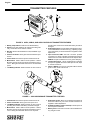
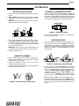
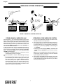
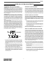
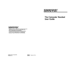
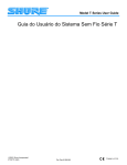
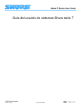
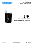
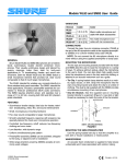
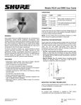
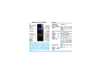
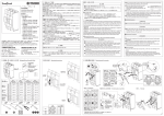
English ACCESS VHF SERIES USER GUIDE This user guide provides detailed instructions for your Access VHF series wireless system. To get your system up and running in minutes, see the Access VHF Series Quick Set Up Guide. Your new Access VHF Series system is designed to give you both the freedom of a wireless system and world-famous Shure sound quality. This manual covers both Single antenna and Diversity versions of the Access VHF Series systems: the AXS31/58 handheld systems; the AXSGW bodypack systems; the AXSHW Headset systems; and the AXSLWD lavalier microphone system. Wireless System AXS31 and AXS58 AXSGW AXSHW AXSLWD Hand-held systems for singers. Bodypack systems for electric and bass guitarists. Can also be used with other electric instruments Bodypack system for applications requiring handsfree operation, such as aerobics or percussion Bodypack system for public speaking, theater, or business presentations. Components Transmitter AXH2 Handheld Transmitter Microphone SM58 or BG3.1 AXB1G Bodypack Transmitter –– Receiver AXB1 Bodypack Transmitter WH20 Headset Microphone WL93 omnidirectional lavalier AXR3 single antenna or AXR4N Diversity Power Supply PS20 (105–125 VAC, 60 Hz) Supplied Accessories Carrying and storage case; Receiver feet; Hook and loop fastening strips; gain adjustment screwdriver microphone stand adapter 1/4” to 1/4” guitar cables (2) RECEIVER FEATURES ÁÁ ÁÁ Á ÁÁÁÁÁÁÁÁ Á ÁÁ Á Á ÁÁÁÁÁÁÁÁ ÁÁ ÁÁÁÁÁÁ Á Á Á Á ÁÁÁÁÁÁÁÁ ÁÁÁÁÁÁÁ ÁÁ Á ÁÁÁÁÁÁ ÁÁÁÁÁ Á ÁÁÁÁÁ ÁÁÁÁÁÁÁ ÁÁÁÁ ÁÁÁÁÁ ÁÁ Á ÁÁÁÁÁÁ ÁÁÁÁÁ ÁÁÁÁÁ ÁÁÁÁÁÁÁ ÁÁÁÁÁ ÁÁÁÁ ÁÁÁÁÁÁ ÁÁÁÁÁ ÁÁÁÁÁÁ ÁÁÁÁÁ ÁÁÁÁÁ Á ÁÁ Á Á ÁÁÁÁÁ ÁÁÁÁ ÁÁÁÁÁÁ ÁÁÁÁÁ ÁÁÁÁÁ Á ÁÁ Á Á ÁÁÁÁ ÁÁÁÁÁ Á ÁÁ ÁÁ Á ÁÁ Á ÁÁÁÁÁÁ ÁÁÁÁÁ ÁÁÁ Á ÁÁ ÁÁÁÁ ÁÁÁÁÁ ÁÁÁÁ ÁÁÁÁÁ Á ÁÁÁÁÁÁ ÁÁÁ 6 7 8 8 1 SQUELCH BALANCED 5 DC INPUT 12–18 VDC MIN MAX 9 6 2 . . . 1 3 AXR3 4 EVANSTON IL 60202 USA HIGH Z 5 Á Á ÁÁ Á ÁÁÁ ÁÁ SHURE BOTHERS INC. UNBALANCED 2 3 4 . . .. .. AXR4N . 7 FIGURE 1. AXR3 AND AXR4N RECEIVER FEATURES 1. Power On Indicator: Glows green when the receiver is powered on. 2. RF Signal Indicator: AXR3: Glows yellow when RF (radio frequency) signals are received. AXR4N: One of two indicator lights glows when RF is received by antenna A or B. 3. Audio Peak Indicator: Flashes red when the audio signal received approaches overload clipping level. 4. Volume Control: Adjusts the output volume of the receiver. Does not affect Transmitter Audio Peak indicator. 5. Telescoping Antenna(s): Receives signals from the transmitter. 6. Audio Output: Provides mic level signal for connection to amplifiers or mixing consoles. AXR3: 1/4 inch phone jack. AXR4N: 1/4 inch phone jack and male XLR connector. 7. Squelch Control: This control is factory pre-set and normally requires no adjustment. See Wireless System Adjustments at the end of this guide. 8. Power Input: Accepts power from supplied AC adapter. 9. Power Cable Retainer: AXR4N only. Secures the AC adapter cable to the receiver. 1 English TRANSMITTER FEATURES ÁÁ ÁÁÁÁ ÁÁÁÁÁÁ Á ÁÁÁÁÁ ÁÁÁÁÁÁÁ ÁÁÁÁ Á ÁÁÁÁÁÁ Á ÁÁÁÁ ÁÁÁÁÁ ÁÁÁÁÁ ÁÁÁÁÁÁÁ ÁÁÁÁ Á ÁÁÁÁ ÁÁÁÁÁ ÁÁÁÁÁÁ Á ÁÁÁÁÁ ÁÁÁÁÁÁÁ ÁÁÁÁ Á ÁÁÁÁ Á ÁÁ Á Á Á ÁÁÁÁÁ ÁÁÁÁÁÁ Á ÁÁÁÁ ÁÁÁÁÁÁÁ ÁÁÁÁ ÁÁ Á Á Á ÁÁ Á ÁÁÁÁÁÁ Á ÁÁÁÁÁ ÁÁÁÁ ÁÁÁÁ Á Á ÁÁÁÁÁÁ ÁÁÁÁÁ ÁÁÁÁ ÁÁÁÁÁÁ Á ÁÁÁÁÁÁ ÁÁÁÁÁ Á Á Á Á ÁÁÁÁÁÁ ÁÁÁÁÁ Á Á Á Á Á ÁÁ Á Á ÁÁ ÁÁ ÁÁ 3 45 6 1 10 11 7 8 9 2 AXB1/AXB1G Bodypack 9 AXB1G FIGURE 2. AXB1, AXB1G, AND AXB11 BODYPACK TRANSMITTER FEATURES 1. Battery Compartment. Holds one 9V alkaline battery. 2. Antenna. For best operation, the antenna must hang vertically, and should not be coiled or bundled. 8. 3. Belt Clip. Secures the transmitter to a belt, waistband or guitar strap. 4. Power On Indicator. Glows green when transmitter is powered on. 9. 5. Power Switch. Recessed to prevent accidental turn-off. 6. Mute Switch. Slide to ON for normal operation. Slide to MUTE to prevent sounds from being transmitted to the receiver. Muting the transmitter does not turn off transmitter power. 10. 11. 7. Low Battery Indicator. Glows red when one hour or less of operating time remains and transmitter battery should be changed. Audio Gain Control. Provides audio level adjustment to accommodate different sound sources (e.g., speaking or playing an instrument). A small screwdriver is supplied to make adjustments. Input Connector. AXB1: Tini Q-G connector provides connection to a variety of lavalier and headset microphone cables and to the Shure WA302 instrument adapter cable. AXB1G: Accepts a standard 1/4 inch or guitar cable plug. Lavalier Microphone. WL93 omnidirectional condenser microphone supplied with a mount that clips onto a tie, lapel, or acoustic instrument. Cables. AXB1G: 1/4 inch to 1/4 inch guitar cable for electric guitar or other electric instruments. Á Á Á ÁÁ Á ÁÁ Á ÁÁ ÁÁÁÁÁ ÁÁ ÁÁÁÁÁ ÁÁ Á ÁÁ ÁÁÁÁÁ ÁÁ ÁÁÁÁÁ ÁÁÁÁÁ ÁÁÁÁÁ Á ÁÁÁ ÁÁÁÁÁÁÁÁÁ ÁÁ ÁÁÁÁ ÁÁÁ Á ÁÁÁ ÁÁÁÁÁÁÁ ÁÁÁÁ ÁÁÁ ÁÁ ÁÁÁÁ ÁÁÁ ÁÁÁ Á ÁÁ ÁÁ Á ÁÁÁÁ ÁÁÁ ÁÁ Á 5 6 1 7 2 3 4 FIGURE 3. AXH2 MICROPHONE-TRANSMITTER FEATURES 5. Audio Gain Control. Allows you to adjust the transmitter to match the loudness of your vocals. A small screwdriver is supplied to make adjustments. 1. Power Switch. Recessed to prevent accidental turn-off. 2. Power On Indicator. Glows green when power is on. 3. Low Battery Indicator. Glows red when one hour or less of operating time remains and battery should be changed. 4. Mute Switch. Slide to ON for normal operation. Slide to MUTE to prevent sounds from being transmitted to the receiver. Muting the transmitter does not turn off power. 6. 9V Alkaline Battery (shown installed). Provides power to the microphone-transmitter. 7. Battery Cover. Unscrews for access to the 9V alkaline battery and gain control. 2 English SYSTEM SETUP BATTERY INSTALLATION BODYPACK TRANSMITTER SETUP 1. Slide the transmitter POWER ON/OFF switch to the OFF position. 2. AXB1, AXB1G: Press down on the OPEN side of the battery compartment cover, slide it back and flip it open, as shown in Figure 4. AXH2: Unscrew the transmitter battery cover to expose the battery terminals, as shown in Figure 3. 1. Attach the transmitter to your belt, guitar strap, or waistband as shown in Figure 6. Depress the tab marked PRESS and slip the belt or strap between the transmitter body and the belt clip. For added stability, draw the strap or belt toward the clip’s top wire, especially when using thin guitar straps. ÁÁÁÁÁ Á Á Á Á Á ÁÁÁÁÁ ÁÁ AXB1/AXB1G - 9V Á Á ÁÁ Á ÁÁÁ Á Á Á ÁÁ Á ÁÁÁÁ ÁÁ Á Á ÁÁÁ Á Á ÁÁ Á Á ÁÁ ÁÁÁ ÁÁ + FIGURE 6. TRANSMITTER SETUP 2. Plug your guitar, headset microphone, or lavalier microphone into the transmitter. FIGURE 4. BATTERY INSTALLATION 3. Insert a fresh 9V alkaline battery into the battery compartment (A Duracell MN1604 is recommended). A fresh 9V alkaline battery will typically provide 18 hours of performance time. A fully charged 8.4V NiCad battery will provide about 2 hours of performance time. RECEIVER SETUP 1. Plug one end of the AC power adapter into the DC INPUT connector on the back of the receiver. AXR4N: Loop the power cable around the cable retainer on the bottom of the receiver. See Figure 7. Plug the other end into an AC power source (use PS20 for 105–125 VAC. The green POWER light on the receiver will glow. IMPORTANT: Carbon-zinc and zinc-chloride batteries will not provide adequate power and are not recommended. 4. Replace the battery cover. HEADSET ASSEMBLY Á Á ÁÁ 1. Refer to the tag attached to the headset for assembly instructions. After assembling the WH20, adjust the headband and place it on your head. 2. Position the microphone over the corner of your mouth, about 1/2 inch away. See Figure 5. 3. To reduce pops and breath noise, place the supplied foam windscreen over the microphone. 1 ÁÁ Á Á ÁÁ ÁÁ Á 2 FIGURE 7. AXR4N POWER CABLE RETAINER 2. Connect the receiver output. The Guitarist: plug a standard guitar cable (two provided) into the receiver’s output connector. Plug the other end into a guitar amplifier, as shown in Figure 8. AXSHW, AXS31, AXS58 or AXSLWD: Use a cable with a 1/4 inch phone plug (AXR3, AXR4N) or a female XLR connector (AXR4N) to connect the receiver to a mic level input of a mixer or PA system, as shown in Figure 8. 3. Extend antenna(s). AXR3: The antenna should be fully extended and vertical, as shown in Figure 8. AXR4N: The antennas should be fully extended and angled away from each other, at an angle of 45 degrees from vertical, as shown in Figure 8. FIGURE 5. HEADSET MICROPHONE POSITION 3 English WIRELESS SYSTEM OPERATION T1G ÁÁ Á Á Á Á ÁÁÁÁÁÁ Á ÁÁ Á Á ÁÁ Á ÁÁÁ ÁÁ ÁÁÁ ÁÁ Á ÁÁÁ Á Á Á ÁÁ AXR3 45° AXR4N 45° SHURE Í È ÁÈ Á Á Á ÁÁ Á ÁÁ ÁÁ Á Á ÁÁÁ ÁÁ ÁÁÁÁ Á ÁÁÁ Á ÁÁÁÁ ÁÁ Á AXR3 SHURE ÁÁÁÁÁÁ ÁÁ ÁÁ ÁÁ ÁÁ Á Á ÁÁ Á 45° Á ÁÁ Á ÁÁ Á AXR4N SHURE 45° Á Á FIGURE 8. WIRELESS SYSTEM OPERATION ESTABLISHING A WIRELESS LINK OPERATING YOUR WIRELESS SYSTEM When powered on, your transmitter broadcasts an RF carrier signal. When picked up by your receiver, this signal links your wireless system together and allows wireless transfer of audio signals from your microphone or instrument. The RF signal is broadcast steadily, even when your transmitter is muted. The yellow RF light (AXR3) and ANTENNA A/B lights (AXR4N) indicate when this link is established. To test your wireless link, setup your transmitter and receiver as described above. Turn on your transmitter while remaining close enough to the receiver to see the yellow RF or ANTENNA lights. The RF light (AXR3) or one of the ANTENNA lights (AXR4N) should illuminate. • If the RF or ANTENNA lights do not illuminate, see the Troubleshooting section in this guide. Turn your transmitter off. The RF or ANTENNA light should go out. • If the RF or ANTENNA lights do not go out after you turn off your transmitter, your receiver is picking up an RF signal from some other source. If you cannot identify and remove this source (usually other digital or wireless electronic equipment nearby), place your receiver in another location. If external RF sources cannot be avoided, you may need a wireless system that operates on a different carrier frequency. Contact your Shure dealer. 1. Once you have established a wireless link, slide the transmitter MUTE switch to the ON position. 2. Sing, speak, or play your instrument at typical volume levels. (AXSGW systems: turn the volume control on your guitar or bass all the way up.) Normal operation is indicated by: • Steady glow of yellow RF light (AXR3) or ANTENNA light A or B (AXR4N). • Flickering of the red PEAK light (AXR3) or TRANSMITTER AUDIO PEAK light (AXR4N) when loud sounds are transmitted. NOTE: If the red TRANSMITTER AUDIO PEAK light on the receiver does not flicker occasionally, refer to the Wireless System Adjustments Section below. 3. When finished, slide the MUTE switch to MUTE. Then slide the transmitter POWER switch to OFF. (Muting the transmitter first will help prevent audio thumps that may occur when powering off the transmitter.) 4 English WIRELESS SYSTEM ADJUSTMENTS TRANSMITTER AUDIO GAIN ADJUSTMENT RECEIVER VOLUME ADJUSTMENT AXSGW Systems: The audio gain control on the transmitter in these systems is factory-preset at the minimum setting (full counterclockwise) to reduce the risk of overload and distortion. If the red TRANSMITTER AUDIO PEAK light on the receiver does not flicker when the guitar is played loudly and its volume controls are turned all the way up, increase the transmitter gain level. This will ensure the best signal-to-noise ratio for performance. See Figure 9. The volume control on the front panel of the AXR3 and AXR4N receivers can be adjusted to make the wireless system output level identical to that of a cabled guitar or bass or wired microphone. After making any necessary transmitter gain adjustments, adjust the receiver volume control until the output reaches the desired level. Rotate the volume control clockwise to increase output. Rotate it counterclockwise to decrease output. AXSHW Systems: The audio gain control on the transmitter in the headset systems is factory preset at the maximum setting (full clockwise). This is because the microphone in the WH20 is a low output, dynamic microphone. It may be necessary to reduce the transmitter gain until the red TRANSMITTER AUDIO PEAK light flickers only when you speak or sing loudly. This will ensure the best signal to noise ratio for performance. See Figure 9. RECEIVER SQUELCH ADJUSTMENT The squelch control on the AXR3 and AXR4N receivers is factory preset for optimum performance. No further adjustment is normally required. It is possible to adjust the squelch control setting to emphasize either signal quality or system range: • Turning the squelch control clockwise causes the receiver AXS31/AXS58/AXSLWD: The audio gain controls on the transmitters in these systems have been factory preset at the midrange position. This will provide the best results in most applications. However, for singers or presenters with quiet voices, the audio gain may need to be increased for better signal-to-noise ratio. Increase the gain until the receiver’s TRANSMITTER AUDIO PEAK light flickers when you speak in a loud voice. For those with loud voices, the preset gain level may be too high, causing unwanted distortion. In this case, the PEAK indicator will glow continuously when you sing or speak in a loud voice and the gain level should be reduced. See Figure 9. ÁÁÁÁÁ Á ÁÁ Á Á Á Á ÁÁÁÁÁ ÁÁ Á Á ÁÁÁÁ ÁÁÁÁ ÁÁ Á ÁÁÁ ÁÁÁ Á Á ÁÁÁÁ ÁÁÁÁ ÁÁ ÁÁÁÁ ÁÁÁ ÁÁÁ to demand a higher quality signal (less noise before muting), but decreases operating range. • Turning the squelch control counterclockwise allows a lower quality signal through (more noise before muting), but increases operating range. To return the receiver squelch control to the factory setting, rotate it to the mid-range position (so the slot is vertical). ABOUT THE SHURE NOISE SQUELCH SYSTEM Conventional squelch circuits analyze RF signal strength. Consequently, they cannot discriminate between noise and desired signals. When a wireless system is used in a noisy RF environment, conventional circuits may “open” unexpectedly, sending loud bursts of noise through the receiver when the transmitter’s signal is weak or turned off. Unlike conventional wireless systems, Shure T-Series systems use a noise squelch circuit that analyzes signal quality instead of signal strength. A special detector monitors the level of high frequency noise. When the transmitter signal is strong, the system’s noise level is low and the receiver sends audio through. When the transmitter signal is weak or absent, the system’s noise level is high and the squelch circuit will mute the receiver. This virtually eliminates the possibility of annoying bursts of noise coming through your receiver. AXB1/AXB1G + -9V AXH2 FIGURE 9. GAIN ADJUSTMENT • To Increase Gain: Rotate the transmitter gain control clock- • • wise with the supplied screwdriver until the red TRANSMITTER AUDIO PEAK light on the receiver flickers when the guitar is played loudly, or when you sing or speak in a loud voice. To Reduce Gain: Rotate the transmitter gain control counterclockwise until the red TRANSMITTER AUDIO PEAK light on the receiver flickers only when the guitar is played loudly, or when you speak or sing in a loud voice. To Return Audio Gain to the Factory Setting: Rotate the transmitter audio gain control counterclockwise as far as it will go (AXSGW systems), clockwise as far as it will go (AXSHW systems), or to mid position (AXS31, AXS58 and AXSLWD Systems). TIPS FOR ACHIEVING MAXIMUM PERFORMANCE • Make sure you can always see a receiver antenna from the transmitter position. • Keep the distance between the transmitter and the receiver antennas short. • Avoid placing the receiver antennas near metal surfaces and obstructions. They will reduce system performance. • To mount the receiver on a flat surface, attach the four adhesive rubber feet or secure the receiver to the surface with the supplied cloth fastening strips. 5 English TROUBLESHOOTING INDICATOR STATUS = on PROBLEM = flickers on loud peaks SOLUTIONS AXR4N RECEIVER TRANSMITTER AXR3 RECEIVER POWER ON A POWER RF POWER TRANSMITTER AUDIO ANTENNA ON No sound. TRANSMITTER AUDIO ANTENNA A B PEAK PEAK B RF POWER TRANSMITTER AUDIO ANTENNA PEAK ON A POWER RF POWER TRANSMITTER AUDIO ANTENNA ON A POWER RF LOW BATT POWER TRANSMITTER ANTENNA AUDIO and into DC input connector on rear panel of receiver. sure AC electrical outlet works and supplies proper voltage. • Make POWER • Slide transmitter MUTE switch to ON. LOW BATT • Extend antenna(s). AXR4N receiver antennas should point away POWER PEAK PEAK match transmitter terminals). • Insert fresh battery. • Make sure AC adapter is securely plugged into electrical outlet POWER PEAK PEAK B LOW BATT PEAK POWER B • Slide transmitter POWER switch to ON. • Make sure battery is inserted properly (+/– battery terminals must POWER LOW BATT • • • No sound or faint sound. ON A POWER RF POWER TRANSMITTER AUDIO ANTENNA ON A POWER RF B B • Increase transmitter gain until Transmitter Audio Peak light flashes POWER on loud peaks. PEAK PEAK LOW BATT POWER PEAK PEAK from each other at a 45° angle from vertical; AXR3 receiver antenna should remain vertical. See Figure 8. Move receiver away from nearby metal objects. Remove obstructions and maintain line of sight between transmitter and receiver. Move transmitter closer to receiver. LOW BATT Sound level from the receiver is different from that of a cabled guitar or microphone. Sound level is different when you change guitars. • Turn up receiver volume control as necessary. • Turn up receiver volume control. • Check cable connection between receiver and amplifier or mixer. • Adjust transmitter gain as necessary. • Adjust receiver volume as necessary. • Adjust transmitter gain to compensate for differences between guitar output levels. POWER • Replace transmitter battery. Distortion increases gradually. Bursts of noise, distortion, or other radio signals interrupt performance. Momentary loss of sound as transmitter is moved around performing area (dropouts). LOW BATT ANTENNA A B LOW BATT RF ANTENNA A RF • If noise occurs when transmitter is turned off, remove or turn off POWER POWER • nearby sources of RF (such as other wireless systems, CB radios, etc.). Use a wireless system that operates on a different frequency. • Reposition B LOW BATT 6 receiver and perform walk-through test. If audio dropouts persist, mark “dead” spots and avoid them during performance. English SYSTEM AND COMPONENT SPECIFICATIONS RF Carrier Frequency Range 169.445 to 240.000 MHz Operating Range:100 m (328 ft.) under typical conditions Audio Frequency Response: 50 to 15,000 Hz, 3 dB Image Rejection: 75 dB typical Spurious Rejection: 75 dB typical System Distortion (ref. 15 kHz deviation, 1 kHz modulation): 0.1% THD typical Signal/Noise Ratio: 102 dB Sensitivity: –110 dBm for 12 dB SINAD typical Operating Temperature Range –18° to 57° C (0° to 135° F) NOTE: Battery characteristics may limit this range. Battery Life: 18 hours with 9 V alkaline battery (Duracell MN1604 recommended). AXR3 AND AXR4N RECEIVER SPECIFICATIONS AXR4N AXR3 Connector 3-Pin XLR (Male) and 1/4” Phone Plug 1/4” Phone Jack Maximum Output Levels at 15 KHz deviation 1/4”: + 5dBV XLR: –10 dBV –6.8 dBV Nominal Output Levels 1/4”: –8 dBV XLR: –30 dBV –32 dBV Output Configuration Active Balanced Unbalanced Actual Impedance 3.3 KΩ 1 KΩ Connector Pin Assignments XLR: Pin 1: ground; Pin 2: hot; Pin 3: cold 1/4”: Tip: hot; Sleeve: ground. Tip: hot; Sleeve: ground Dimensions (AXR4N) 41 mm H x 197 mm W x 138 mm D (1.625” H x 7.77” W x 5.42” D) Dimensions (AXR3) 35mm H x 152 mm W x 98 mm D (1.38”H x 5.98” W x 3.85” D) 1/4 Inch (AXB1G); 4-pin Tini Q-G (AXB1) 1 MΩ Net Weight (AXR4N) 435 g (15.4 oz.) Net Weight (AXR3) 192 g (6.8 oz.) +12 dBV Power Requirements 12–18 VDC nominal, 200mA Power Supply 120 V or 230V AC adaptor with 2.1 mm female plug AXB1, AXB1G BODYPACK TRANSMITTER SPECIFICATIONS RF Output Input Configuration Connector Type Actual Impedance Maximum Recommended Input Level* Minimum Recommended Input Level** 50 mW Typical Connector Pin Assignments (AXB1) Pin 1:Tied to Ground Pin 2:Tied to +5 V Pin 3:Tied to Audio Pin 4:Tied to 20kΩ Resistor and Audio Ground Connector Pin Assignments (AXB1G) Dimensions Net Weight Power Requirements Nominal Current Drain Unbalanced –80 dBV Voltage/Current/Phant Yes om Power Protection Certification AXB1G, AXB1:Accepted under FCC Parts 74 and 90. Certified by IC in Canada under TRC-78. AXH2/31, AXH2/58: Type Accepted under FCC Parts 74 and 90. Certified by IC in Canada under TRC-78. Conforms to European Union directives, eligible to bear CE marking; meets European Union Requirements. Type Approval: pr I–ETS 300 422, BZT 17 TR 2019, and BAPT 122 R 1. EMC Immunity: pr ETS 300 445. AXR3, AXR4N: Approved under the Declaration of Conformity provision of FCC Part 15 (AXR3). Certified by IC in Canada under RSS 123 (AXR4N). Conforms to European Union directives, eligible to bear CE marking; mets European Union Requirements. EMC Immunity: pr ETS 300 445. Power supply meets Low Voltage Directive: 73/23/EEC. Sleeve: Tied to Ground Tip: Tied to Audio 64 mm H x 106 mm W x 24 mm D (2.52” H x 4.17” W x 0.95” D) 96.4g (3.4 oz.) 9 V alkaline battery (Duracell MN1604 recommended); 8.4 V NiCd battery optional. 30 mA * Gain Control at minimum ** Gain Control at maximum AXH2 HAND-HELD TRANSMITTER SPECIFICATIONS AXH2/58 (SM58) AXH2/31(BG3.1) RF Output 50 mW Typical (FCC); 20 mW Typical (ETSI) Dimensions 236 mm H x 51 mm D (9.29” H x 2.01” D) 222 mm H x 51 mm D (8.74” H x 2.01” D) Net Weight 295g (10.4 oz.) 266g (9.4 oz.) Power Requirement 9 V alkaline battery (Duracell MN1604 recommended); 8.4 V NiCd battery optional. Nominal Current Drain 30 mA Yes 30 mA 7 English ACCESSORIES, LICENSING AND WARRANTY FURNISHED ACCESSORIES DECLARATION OF CONFORMITY Screwdriver . . . . . . . . . . . . . . . . . . . . . . . . . . . . . . . . 65A1659 Sew–in Mounting Block (WL93 AXSLWD Only) . . . . . . . . . . . . . . . . . . . 65B1733* Receiver AC Adapter . . . . . . . . . . . . . . . . . . . . . PS20 (120V) Guitar Cables (2) (AXSGW systems Only) . . . . . . . WA303 Swivel Adapter (AXS31/58 systems Only) . . . . . . . . WA371 Plastic Carrying Case (Diversity Systems) . . . . . . . WA605 Plastic Carrying Case (Single Antenna systems) . . WA600 We of Shure Incorporated 222 Hartrey Ave. Evanston IL 60202–3696 U.S.A. 847–866–2200 declare under our sole responsibility that the following products, OPTIONAL ACCESSORIES Model: AXR3 Model: AXR4N Anti–Roll Device for Handheld Transmitters . . . . . . . . . A1K Neoprene Bodypack Belt Pouch . . . . . . . . . . . . . . . . WA570 Line Matching Output Transformer (AXR3 Receiver) . A95U 1.8 Meter (6 ft.) Receiver-Mixer Cable . . . . . . . . . . . WA410 Rack-Mount Kit (AXR4N Diversity Systems Only) . . . . URT Amp/Powered Mixer stand for Receivers . . . . . . . . . WA595 AXSLWD Systems Only Tan version of WL93 . . . . . . . . . . . . . . . . . . . . . . . . . . WL93T Single-Mount Tie Clip (2) (WL93) . . . . . . . . . . . . . . . . . . . . . . . . . . . . . . . . . RK354SB Dual-Mount Tie Clip (WL93) . . . . . . . . . . . . . . . . . . . . . . . . . . . . . . . . . RK307DB Black Windscreen (4) (WL93) . . . . . . . . . . . . . . . . . . . . . . . . . . . . . . . . . RK355WS Tan Windscreen and Tie Clip (2 each) (WL93) . . . . . . . . . . . . . . . . . . . . . . . . . . . . . . . . . . . RK304T AXSHW Systems Only Foam Windscreens (2) and Clothing Clip (WH20) RK318WS Croakies Headband (WH20) . . . . . . . . . . . . . . . . . . . RK319 Croakies Headband and Wire Frame (WH20) . . RPM600 Microphone and Boom Assembly (WH20) 1/4” plug . . . . . . . . . . . . . . . . . . . . . . . . . . . . . . . . RPM100 Name: AXR3 Receiver Name: AXR4N Diversity Receiver were tested and found to comply with Part 15 of the FCC rules. Operation is subject to the following two conditions: (1) this device may not cause harmful interference, and (2) this device must accept any interference received, including interference that may cause undesired operation. Testing was completed by the following NVLAP or A2LA accredited laboratory: BZT privat CETECOM GmbH 66117 Sarbruken Unterturkheimer StrBe 6–10 Deutschland telephone +49 681 598 – 9000 fax +49 681 598 – 9075 Shure Inc., Manufacturer. ∗ Furnished in multiples of 4. ∗∗ Includes 2 tie bars and 2 windscreens. For additional microphone service or parts information, please contact Shure’s Service department at 1–800–516–2525 or Shure’s website at www.shure.com. Outside the United States, please contact your Authorized Shure Service Center. Signed: Date: June 15, 1999 Name, Title: Craig Kozokar, Senior Quality Engineer WARRANTY INFORMATION ADDITIONAL INFORMATION FOR THIS SHURE WIRELESS SYSTEM Shure Incorporated (“Shure”) hereby warrants that these products will be free from defects in material and workmanship for a period of two years from the date of purchase for all microphone cartridge and housing assembly parts and, for a period of one year from the date of purchase, all transmitter and receiver parts. At its option, Shure will repair or replace the defective product and promptly return it to you. You should retain proof of purchase to validate the purchase date and return it with any warranty claim. If you believe this product is defective within the warranty period, carefully repack the unit, insure it, and return it postpaid to: Shure Incorporated Attention: Service Department 222 Hartrey Avenue Evanston, IL 60202-5730 U.S.A. Customers outside the U.S.A. should ship the product to the authorized Shure Distribution Center in their region. This Shure wireless transmitter is accepted under FCC Part 74 and/or Part 90. IMPORTANT: Licensing of Shure wireless microphone equipment is the user’s responsibility, and licensability depends on the user’s classification and application, and on the selected frequency. Shure urges the user to consult the appropriate telecommunications authority before choosing and ordering frequencies. Changes or modifications not expressly approved by Shure Inc. could void your authority to operate this equipment. 8