1
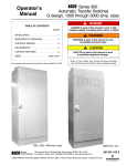
Operator’s Manual Series 300 Automatic Transfer Switches G design 1000 through 3000 amps 1000, 1200, 1600 amp. sizes 2000 amp. size An experienced licensed electrician must install the ATS. DANGER is used in this manual to warn of high voltages capable of causing shock, burns, or death. TABLE OF CONTENTS section ! WARNING is used in this manual to warn of possible personal injury. ! SEQUENCE OF OPERATION . . . . . . . . . . . . . 2 TESTING & SERVICE . . . . . . . . . . . . . . . . . . . . 3 CAUTION is used in this manual to warn of possible equipment damage. Refer to the outline and wiring drawings provided with ASCO Series 300 ATS for all installation details. ASCO POWER TECHNOLOGIES L.P. INSTALLATION . . . . . . . . . . . . . . . . . . . . . . . . . . 1 ADJUSTMENTS . . . . . . . . . . . . . . . . . . . . . . . . . 4 CONTROL FEATURES . . . . . . . . . . . . . . . . . . . 5 INDEX . . . . . . . . . . . . . . . . . . . . . . . . . back cover 50 Hanover Road, Florham Park, New Jersey 07932 USA www.asco.com 381333–122 B Nameplate Catalog Number Indentification The Transfer Switch nameplate includes data for each specific ASCO Series 300 ATS. Use the ATS only within the limits shown on this nameplate. A typical Catalog Number is shown below with its elements explained. The example is for a G–design Series 300 ATS with switched neutral, 3 pole, 2000 amp, 480 V, in a Type 1 enclosure: G300 Neutral B – switched C – overlapping blank – solid Phase Poles 2 – single Ø 3 – three Ø 3 2000 Amperes 1000 1200 1600 2000 2600 3000 N Voltage C 208 D 220 E 230 F 240 H 380 J 400 K 415 neutral connections 1 L 440 M 460 N 480 P 550 Q 575 R 600 C Controller Enclosure 1 – standard C – type 1 F – type 3R G – type 4 * L – type 12 * 1X – if accessories ordered blank – open type * type 4 & 12 enclosures are available only for 1000, 1200, & 1600 amp. sizes terminal block TB for engine start and switch position contacts power connections Controller membrane controls Transfer Switch power connections neutral connections 2000 amp. size in typical enclosure with location of customer connections SECTION 1 INSTALLATION Auxiliary Cable Box for 1000–2000 amp ASCO Series 300 Automatic Transfer Switches (ATSs) are Listed under Underwriters Laboratories UL 1008 Standard for Safety for Automatic Transfer Switches. All control features are UL Component Recognized, which assures that ASCO automatic transfer switches meet OSHA Safety Requirements and will be acceptable to electrical inspectors. An auxiliary cable box is required if the power cables do not enter the enclosure directly adjacent to the terminal lugs (for example, if all power cables enter the top or bottom). Order ASCO part no. 609027 if needed. ! ASCO Series 300 Automatic Transfer Switches are suitable for emergency and standby system applications. They meet emergency system rating requirements as defined in National Electrical Code (NEC) Article 700 and UL 1008. Also, they are suitable for the requirements of NEC Article 517 – Health Care Facilities, NEC Article 701 – Legally Required Standby Systems, NEC Article 702 – Optional Standby Systems, NFPA 99 Health Care Facilities, and NFPA 110 Emergency and Standby Power Systems. Do not route the power cables along the sides of the Transfer Switch. Line Connections Refer to the Wiring Diagram provided with your Series 300 ATS. All wiring must be made in accordance with the National Electrical Code and local codes. It is unnecessary to remove pole covers from the transfer switch. If you do remove them, reinstall them carefully. Rating Label Each automatic transfer switch contains a rating label to define the loads and fault circuit withstand / closing ratings. Refer to the label on the transfer switch for specific values. De–energize the conductors before making any line or auxiliary circuitry connections. Be sure that Normal and Emergency line connections are in proper phase rotation. Place engine generator starting control in the OFF position. Make sure engine generator is not in operation. ! Do not exceed the values on the rating label. Exceeding the rating can cause personal injury or serious equipment damage. Testing Power Conductors Series 300 Automatic Transfer Switches are factory wired and tested. Installation requires skid removal then securing the enclosure to the supporting foundation. Do not connect the power conductors to the ASCO Series 300 transfer switch until they are tested. Installing power cables in conduit, cable troughs and ceiling-suspended hangers often requires considerable force. The pulling of cables can damage insulation and stretch or break the conductor’s strands. For this reason, after the cables are pulled into position, and before they are connected, they should be tested to verify that they are not defective or have been damaged during installation. Remove the Shipping Skid Open the front door and remove the four lag screws (two in front, two in rear) securing the enclosure to the wood skid. Supporting Foundation The supporting foundation for the enclosure must be level and straight. Refer to the applicable enclosure outline drawing included with the Series 300 for all mounting details including door opening space. ! Protect the automatic transfer switch from construction grit and metal chips to prevent malfunction or shortened life of the ATS. If bottom cable entry is used, the foundation must be prepared so that the conduit stubs are located correctly. Refer to the enclosure outline drawing for specified area and location. Provide cable bending space and clearance to live metal parts. When a concrete floor is poured, use interlocking conduit spacer caps or a wood or metal template to maintain proper conduit alignment. Connecting Power Conductors After the power cables have been tested, connect them to the appropriate terminal lugs on the transfer switch as shown on the wiring diagram provided with this Series 300. Make sure the lugs provided are suitable for use with the cables being installed. Standard terminal lugs are solderless screw type and will accept the wire sizes listed on the drawings provided with the Series 300. Be careful when stripping insulation from the cables; avoid nicking or ringing the conductor. Remove surface oxides from cables by cleaning with a wire brush. When aluminum cable is used, apply joint compound to conductors. Tighten cable lugs to the torque specified on rating label. Mounting Refer to the applicable enclosure outline drawing furnished with this switch and mount the Series 300 according to details and instructions shown on diagram. 1--1 INSTALLATION (continued) Controller Ground Harnesses A grounding wire must be connected to the controller’s lower left mounting stud. Because the controller is mounted on the enclosure door, a conductive strap must be used between the enclosure and the door. This connection provides proper grounding which does not rely upon the door hinges. The transfer switch is connected to the left side of the controller by a plug–in harness (two plugs). Engine Starting Contacts Customer connections for engine control contact and TS auxiliary contacts connections are located on terminal block TB which is mounted on the front lower left of the transfer switch. Refer to wiring diagram provided with the Series 300 ATS and connect the engine start wires to the appropriate terminals. See Figure 1–1 and Table A. Engine Starting Signals TS Auxiliary Contacts Feature 14A & 14B 5 amps, 32 V DC 5 amps resistive 28 V DC or 120 V AC max. 10 amps, 32 V DC 10 amps 250 V AC general purpose Table A. Engine start connections. When normal source fails contact closes contact opens TB Terminal Block (field connections) accepts wire range 22–12 AWG Terminals on transfer switch TB1 and TB3 TB1 and TB2 Auxiliary Circuits Figure 1-1. Connections to engine starting contact terminal block located on the Transfer Switch. Connect auxiliary circuit wires to appropriate terminals on transfer switch terminal block TB as shown on the wiring diagram provided with this Series 300 Automatic Transfer Switch. Make the necessary auxiliary connections by referring to Section 5, Control Features. Programmable Load Disconnect Engine Exerciser Feature connection, Connections if provided (see Wiring Diagram (refer to & refer to page 5–3 for DIP switch settings) page 5–2) Connections to Controller for other Control Features (located on bottom of Controller) Remote Control Features Connections (refer to the Wiring Diagram & page 5–3 for DIP switch settings) Each control contact must be suitable for a 5 V DC low energy circuit. for factory use only Figure 1-2. Input / output label on the Controller showing possible connections to the lower terminal block. 1--2 INSTALLATION (continued) Functional Test The Functional Test consists of three checks: manual operation, voltage checks, and electrical operation. Turn counterclockwise to Emergency. ! Turn clockwise to Normal. Do these checks in the order presented to avoid damaging the automatic transfer switch. slide hub onto shaft Read all instructions on the Wiring Diagram and labels affixed to the automatic transfer switch. Note the control features that are provided and review their operation before proceeding. Figure 1-3. Maintenance handle. 1 – Manual Operation Test 1. After deenergizing both power sources, open the enclosure door. Locate and remove the maintenance handle and hub stored on the transfer switch frame. Then install the hub onto the center operator shaft and insert the handle firmly into the hole in the side of the hub (spring fully compressed). See Figure 1–3 and 1–4 and Table B. 2. If the transfer switch is closed on Normal (window shows CLOSED), grasp handle firmly and turn it counterclockwise. The transfer switch should operate smoothly without binding. If it does not, check for shipping damage or construction debris. 3. Turn the handle clockwise to return the transfer switch to the Normal position. Observe that the window indicators (left side) show the top shaft OPEN and the bottom shaft CLOSED. A detachable maintenance handle is provided on the frame of the Transfer Switch for maintenance purposes only. Manual operation of the transfer switch should be checked before it is energized (operated electrically). ! Do not manually operate the transfer switch until both power sources are disconnected: open both circuit breakers. Table B. Maintenance handle positions. ATS Position Indicators OPEN E upper contacts open Normal CLOSED N lower contacts closed E CLOSED insert handle into hole Grasp handle firmly 4. Note: If Normal and Emergency connections are reversed this operation is also reversed. Remove the maintenance handle and hub and store it on the frame in the place provided. upper contacts closed Emergency ! OPEN N Verify that the maintenance handle and hub have been removed before proceeding! lower contacts open Now continue to 2 – Voltage Checks on next page. Emergency contacts window indicators OPEN or CLOSED Normal contacts contact position indicators (left side) counterclockwise DOWN closes the Emergency source contacts (upper) and opens the Normal source contacts (lower) clockwise DOWN closes the Normal source contacts (lower) and opens the Emergency source contacts (upper) Figure 1-4. Contact position indicators and maintenance handle operation. 1--3 INSTALLATION (continued) Florham Park NJ 07932 USA observe these lights TRANSFER SWITCH TEST BYPASS TIME DELAY Press for 15 Seconds SET ENGINE EXERCISER Press until light FLASHES Figure 1–5. Standard controls and indicators. 2 – Voltage Checks Close the normal source circuit breaker. The Transfer Switch 1 Connected To Normal and the Normal Source Available lights should come on. First check nameplate on transfer switch; rated voltage must be the same as normal and emergency line voltages. ! Verify that the feeders have been connected to the proper lugs. Use an accurate voltmeter to check phase to phase and 2 phase to neutral voltages present at the transfer switch normal source terminals. Use extreme caution when using a meter to measure voltages in the following steps. Do not touch power terminals; shock, burns, or death could result ! Close the emergency source circuit breaker. (Start generator, if necessary.) The Transfer 3 Switch Connected To Normal and the Emergency Source Available lights should come on. Perform steps 1 through 6 at the right. Observe the status lights. See Figure 1–5. ● Black circle means light is on. Use an accurate voltmeter to check phase to phase and 4 phase to neutral voltages present at the transfer switch emergency source terminals.* ❍ White circle means light is off. * If necessary, adjust voltage regulator on the generator according to the manufacturer’s recommendations. The Automatic Transfer Switch will respond only to the rated voltage specified on the Transfer Switch nameplate. Use a phase rotation meter to check phase rotation of emer5 gency source; it must be the same as the normal source. A B C Shut down the engine–generator, if applicable. The Emergency Source Accepted light should 6 go off. Then put the starting control selector switch (on the generator set) in the automatic position. Close enclosure door. Now continue to 3 – Electrical Operation on next page. 1--4 INSTALLATION (continued) Florham Park NJ 07932 USA observe these lights press this button TRANSFER SWITCH TEST BYPASS TIME DELAY Press for 15 Seconds SET ENGINE EXERCISER Press until light FLASHES Figure 1–6. Standard controls and indicators. 3 – Electrical Operation The normal source must be available and the generator 1 must be ready to start. Check that the Normal Source Available light is on. First check nameplate on transfer switch; rated voltage must be the same as normal and emergency line voltages. ! Press and hold the Transfer Switch Test button until the 2 engine starts and runs. This should happen within 15 sec. Verify that the feeders have been connected to the proper lugs. 3 Use extreme caution when using a meter to measure voltages in the following steps. Do not touch power terminals; shock, burns, or death could result ! Perform steps 1 through 8 at the right. Observe the status lights. See Figure 1–6. 4 ● Black circle means light is on. ❍ White circle means light is off. NOTE: If Motor Load Transfer feature is activated, then transfer may not occur immediately after the respective time delays. Transfer will only occur when the phase relationship between sources is correct. 5 6 This completes the Functional Test of the ASCO Series 300 Automatic Transfer Switch. Leave the engine–generator starting control in the automatic position. 7 The Emergency Source Available light should come on. The transfer switch should transfer to the Emergency position. The Load Connected to Emergency light should come on and the Load Connected to Normal light should go off. If the transfer to emergency delay is used the transfer should occurs after a time delay (up to 5 minutes). For immediate transfer press the Bypass Time Delay button. The transfer switch should transfer back to the Normal position. The Load Connected to Normal light should come on and the Load Connected to Emergency light should go off. If the retransfer to normal delay is used the retransfer should occur after a time delay (up to 30 minutes). For immediate retransfer press the Bypass Time Delay button. The unloaded running delay keeps the generator running for 5 minutes (cool–down period). 8 Then the generator should stop and the Emergency Source Available light should go off. 1--5 TRANSFER SWITCH TEST BYPASS TIME DELAY BYPASS TIME DELAY SECTION 2 SEQUENCE OF OPERATION lights show position of transfer switch lights show the sources available Transfer To Emergency The sequence for load transfer to emergency source begins automatically when normal source voltage falls below the preset dropout point or when Transfer Switch Test button is pressed. An under voltage condition on any phase of the normal source is detected by the sensor. light for built–in engine exercise timer Florham Park NJ 07932 USA · blinks rapidly when button is held 5 sec. while being set · blinks slowly when button is released (set) and during 20 min. exercise period. TRANSFER SWITCH TEST BYPASS TIME DELAY SET ENGINE EXERCISER · stays on after engine stops (exerciser is enabled for weekly operation) When the normal Press for 15 Seconds Press until light FLASHES source voltage fails or the Transfer Switch Test See page 5–1 button is pressed, the for complete Hold 5 sec. to set Press to cancel the instructions SE relay de-energizes Hold 15 sec. to active exercise period 20 min. engine exercise start the engine and relay NR begins its generator and to (stops engine now or period immediately (engine timing cycle (1 or 3 transfer the load after cooldown) See starts) and weekly thereafter. page 5–1. seconds, momentary to emergency. Figure 2–1. Membrane controls and indicator lights. normal source outage Retransfer to Normal delay). The NR relay is provided with a time delay on dropout to override momentary outages and prevent The sequence for load retransfer to the normal source nuisance starting of the engine-driven generator. If the automatically begins when the voltage sensor detects normal source voltage returns above the sensor dropout restoration of the normal source. The voltage level must setting before the time delay expires, the NR relay timing rise above the preset pickup point on all phases before cycle is reset to zero and relay SE energizes. the sensor will accept the normal source. If the normal source voltage does not return above the sensor dropout setting before the time delay expires, the NR relay de-energizes and signals the engine-driven generator to start. At the same time, a voltage and frequency sensor begins monitoring the emergency source. The sensor will accept the emergency source only when both voltage and frequency reach preset pickup points. Usually about ten seconds elapse from dropout of the NR relay to acceptance by the sensor. This time span occurs because the engine-driven generator must crank, start, and run up to nominal pickup points. For this reason, if the Transfer Switch Test button is pressed it must be held for 15 seconds. If the emergency source is available immediately, the sensor may accept it as soon as NR relay drops out. When the normal source is accepted by the sensor, relay SE begins its timing cycle (adjustable 1 sec. to 30 min., retransfer to normal delay). For immediate retransfer press Bypass Time Delay button. SE relay is provided with a time delay on pickup to prevent immediate load retransfer to the normal source. The delay insures that the normal source has stabilized before reconnection of vital loads. If the normal source voltage falls below the present dropout point before the time delay expires, the timing cycle is reset to zero. If the emergency source fails for more than 4 seconds during the timing cycle, ER relay drops out and the load is immediately retransferred to the normal source, if that source is acceptable. SE relay energizes and ER relay is dropped out. The TS coil is energized, the transfer switch operates, and all switch contacts (mains, controls, auxiliaries) reverse position. The transfer switch is now supplying the load from the normal source again. When the emergency source is accepted by the sensor, relay ER begins its timing cycle (transfer to emergency delay). ER relay is provided with an adjustable (0 to 5 minutes) time delay on pickup to delay transfer of the load to the emergency source. For immediate transfer press Bypass Time Delay button. Upon retransfer to the normal source, NR relay begins its timing cycle (unloaded running delay [engine cooldown] ). NR relay is provided with a 5 minute time delay on pickup to keep the engine running for a cool-down period. ER relay energizes, the TS coil is energized, the transfer switch operates, and all switch contacts (mains, controls, auxiliaries) reverse position. The transfer switch is now supplying the load from the emergency source. NR relay energizes after the time delay and signals the engine-driven generator to shut down. All circuits are reset for any future normal source failure. The transfer switch will remain in the Emergency position until the normal source is restored. If the Transfer Switch Terst button is used, the transfer switch will remain on emergency until the retransfer to normal delay times out. Activation of standard control features shown in Section 5 will alter the sequence of operation and introduce additional time delays during transfer operations. 2--1 SECTION 3 TESTING & SERVICE PREVENTIVE MAINTENANCE DISCONNECTING THE CONTROLLER Reasonable care in preventive maintenance will insure high reliability and long life for the automatic transfer switch. The harness disconnect plugs are furnished for repair purposes only and should not have to be unplugged. If the controller must be isolated, follow these steps carefully. Operate the switch at least once a month. Perform this four step Electrical Operation Test. This is a test with load transfer. Disconnecting the Plugs ! Do not unplug the controller until step 1a. or 1b. below is completed. 1. Observe the position of the transfer switch. a. If the transfer switch is in the Normal position, place standby engine starting control in the off position. Then open the emergency source circuit breaker. TRANSFER SWITCH TEST Press for 15 Seconds BYPASS TIME DELAY b. If the transfer switch is in the Emergency position, open the normal source circuit breaker. Place the engine starting control in the test or run position. SET ENGINE EXERCISER 2. Separate the quick disconnect plugs by squeezing the latches. Do not pull on the harness wires. Press until light FLASHES 3. Label, remove, and tape the signal wires connected to the engine start terminals on the transfer switch: TB1 and TB3, or TB1 and TB2. Transfer Switch Test 1. Press and hold the door-mounted TRANSFER SWITCH TEST button until the engine starts and runs. This should happen within 15 seconds. Reconnecting the Plugs ! 2. The transfer switch will operate to the Emergency position. If the Transfer To Emergency Delay is used, the transfer will occur after a time delay (up to 5 minutes). For immediate transfer press BYPASS TIME DELAY button. Do not reconnect the controller until step 1a. or 1b. and 2 below are completed. 1. Observe the position of the transfer switch. a. If the transfer switch is in the Normal position, be sure that the standby engine starting control is still in the off position. The emergency source circuit breaker still should be open. 3. The Transfer Switch will operate back to the Normal position after the Retransfer To Normal Delay (up to 30 minutes). For immediate retransfer press BYPASS TIME DELAY button. b. If the transfer switch is in the Emergency position, normal source circuit breaker still should be open. 2. Reconnect the signal wires connected to the appropriate engine start terminals on the transfer switch. See Section 1, Engine Starting Contacts. 4. Unloaded Running (Engine Cooldown) Delay allows engine to run unloaded for 5 minutes. Clean and inspect the switch once a year. De-energize all sources, then brush and vacuum away any excessive dust accumulation. Remove the transfer switch barriers and check contact condition. Replace contacts when pitted or worn excessively. Reinstall the barriers carefully. 3. The harness plugs and sockets are keyed. Carefully align the plugs with the sockets and press straight in until both latches click. 4. Restore the opposite source as follows: a. If the transfer switch is in the Normal position, place the standby engine starting control in the automatic position. Then close the emergency source circuit breaker. Maintain transfer switch lubrication. The transfer switch has been properly lubricated, and under normal operating conditions no further lubricating is required. Renew factory lubrication if the switch is subjected to severe dust or abnormal operating conditions. Relubricate the operator if TS coil is replaced. Order lubrication kit 75-100. b. If the transfer switch is in the Emergency position, close the normal source circuit breaker. The load will be automatically retransferred to the normal source after the Retransfer to Normal Delay. For immediate retransfer, press BYPASS TIME DELAY button. Place the engine starting control in the automatic position. Replacement parts. Replacement parts are available in kit form. When ordering parts provide the Serial No. and Catalog No. from the transfer switch nameplate. Contact your local ASCO Power Technologies sales office. 3--1 TESTING & SERVICE (continued) MANUAL LOAD TRANSFER 1. Open normal and emergency source circuit breakers. This procedure will manually transfer the load if the controller is disconnected. 2. Use the maintenance handle to manually operate transfer switch to the opposite source. See page 1–3, Manual Operation Test. ! Do not manually operate the transfer switch until both power sources are disconnected: open both circuit breakers. 3. If the transfer switch is in the Emergency position manually start the engine generator and then close the emergency source circuit breaker. TROUBLE-SHOOTING Note the control features that are activated or furnished on the switch and review their operation. Refer to Section 5, Control Features. ! Proceed with care! The automatic transfer switch is energized. Table 3-1. Trouble-Shooting Checks. CHECK IN NUMERICAL SEQUENCE PROBLEM 1 OPERATION Gen-Set does not start when Hold the TRANSFER SWITCH the TRANSFER SWITCH TEST TEST button 15 sec. or the button is pressed and held for outage must be long enough 15 seconds or when the to allow for the 1 or 3 sec. normal source fails. Momentary Normal Source Outage Delay plus engine cranking and starting time. 2 GEN-SET Starting control must be in automatic position. Batteries must be charged and connected. Check wiring to engine starting contacts. 3 VOLTAGE Transfer switch does not transfer the load to emergency source after the gen-set starts. Wait for Transfer to Emergency Delay (0 to 5 min.) to time out. For immediate transfer, press the BYPASS TIME DELAY button. If Motor Load Transfer is active, wait for inphase condition (see below). Generator output circuit breaker must be closed. Generator frequency must be at least 57 Hz. Voltmeter should read at least 90% of nominal phase to phase voltage between transfer switch terminals EA and EC (or EL1 and EL2 for 2 pole switches). * * These are factory settings. Transfer switch does not transfer the load to normal source when normal returns or when TRANSFER SWITCH TEST button is released. Wait for Retransfer to Normal Delay (1 sec. to 30 min.) to time out. For immediate re– transfer, press BYPASS TIME DELAY button. If Motor Load Transfer is active, wait for inphase condition (see below). Gen-Set does not stop after load retransfer to the normal source. Wait for the 5 minute Unloaded Running Delay to time out. — — Voltmeter should read at least 90% of nominal phase to phase voltage between transfer switch terminals NB and NC, NC and NA, and NA and NB (or NL1 and NL2 for 2 pole switches). Starting control must be in automatic position. — Trouble-Shooting the Motor Load Transfer Feature (refer to page 5–3) 3. Press and hold TRANSFER SWITCH TEST button. The load should transfer to emergency source when meter needle is near 0 volts. If transfer does not occur, Motor Load Transfer feature is not operating. 4. Release the Transfer Switch Test button. The load should retransfer back to the normal source after the Retransfer to Normal Delay, if used. The retransfer should occur when the needle is near 0 volts. If retransfer does not occur after the time delay, the Motor Load Transfer feature is not operating. 5. For immediate retransfer, press the BYPASS TIME DELAY button. Then disconnect the voltmeter. Use extreme caution when using a meter to measure voltages in the following steps. Do not touch power terminals; shock, burns, or death could result ! 1. Connect a voltmeter (set for twice system phase–to–phase voltage) between Transfer Switch terminals NA and EA. 2. Manually start generator. Voltmeter needle should sweep back and forth at a regular rate between 0 and about twice system voltage. If the problem is isolated to circuits on the controller or the transfer switch, call your local ASCO Power Technologies sales office. Furnish Serial No., Bill of Material (BOM) No., & Catalog No. from the transfer switch nameplate. 3--2 SECTION 4 ADJUSTMENTS Time Delay Adjustment To change a setting, follow procedure on page 4-2. Use Table 4-1 as a guide to time delay values and their corresponding adjustment DIP switch or potentiometer. Standard time delays are set to customer specifications (if none specified, standard factory settings are used). Table 4-1. Time Delay Settings DESCRIPTION LABELS FACTORY SETTING Override Momentary Normal Source Outages TD ES 3 seconds Transfer to Emergency TIMER N/E Override Momentary Emergency S. Outages ADJUSTMENT RANGE S3 DIP SWITCH ADJUSTMENT POTENTIOMETER Actuator 1 on 3 seconds Actuator 1 off 0 minutes (full ccw) 0 to 5 minutes — — P2 — 4 seconds non-adjustable — — — Retransfer to Normal TIMER E/N 30 minutes (full cw) 1 second to 30 minutes — — P1 Unloaded Running (Engine Cooldown) — 5 minutes non-adjustable — — — ! Voltage and frequency sensor pickup and dropout points are set to customer specifications (if none specified, standard factory settings are used). To change a setting, follow procedure on page 4–2. Use Tables 4-2 and 4–3 for settings and corresponding DIP switch actuators. Any change in these settings may affect the normal operation of the automatic transfer switch. This change could allow the load circuits to remain connected to a low voltage source. Table 4-2. Voltage and Frequency Settings. ( DESCRIPTION DO / N Emergency Source Voltage Actuator 3 on 90 % * Actuator 1 off Actuator 2 off 85 % Actuator 1 on Actuator 2 off 80 % Actuator 1 off Actuator 2 on 70 % Actuator 1 on Actuator 2 on –– Pickup 90 % non-adjustable –– Dropout 75 % non-adjustable 95 % non-adjustable Dropout 85 % non-adjustable 60 / 50 Hz 60 / 50 Hz 60 Hz 34,14 34/14 34 –– 60 Hz Actuator 4 off 50 Hz Actuator 4 on 3 phase Actuator 6 off 1 phase Actuator 6 on 6 Pickup –– 6 –– –– 4 Voltage Phases 90 % 4 Emergency S E Source Frequency q y 85 % D Dropout t Actuator 3 off 1 2 Normal Source Voltage 95 % * 1 2 90 % 1 2 Pickup S1 DIP SWITCH ADJ RANGE 1 2 PU / N % of nominal FACT. SET 3 SETTING Shaded DIP switches are standard factory settings). 3 LABELS — 1 Sensor Adjustments 1 1 second * If dropout voltage is set to 90%, the pickup voltage must be set to 95%. Table 4-3. Transformer Voltage Adjust. (Low setting shifts all voltage settings down 4.2%; for example, 240 V to 230 V, or 480 V to 460 V) FACTORY SETTING Voltage Adjust (4 (4.2%) 2%) LOW / HI HI 4--1 ADJUSTMENT S3 DIP SWITCH LOW Actuator 2 off HI Actuator 2 on 2 LABELS 2 DESCRIPTION ADJUSTMENTS (continued) ! Do not make any setting changes while the controller is energized. thumb latch cover How to Change a Setting 1. Prevent the transfer switch from operating by disconnecting one source first, then the other, as follows: a. b. hook on left side If the transfer switch is in the Normal position, open the emergency source circuit breaker. Turn the engine starting control to off. Then open the normal source circuit breaker. Figure 4-1. Controller cover latch. If the transfer switch is in the Emergency position, open the normal source circuit breaker. Turn engine starting control to test or run. Then open the emergency source circuit breaker. 2. Disconnect both harness plugs from controller by squeezing the latches. Do not pull on the wires. 9 volt alkaline battery 3. Remove cover from the controller by releasing latch on right side with your thumb. See Figure 4-1. 4. Locate the appropriate adjustment potentiometer or DIP switch for the setting that you want to change. Refer to Table 4-1 and Table 4–2 on page 4-1 and Figure 4-2, Figure 4–3, Figure 4–4 on page 4–2. retransfer to normal time delay S1 DIP switch S2 DIP switch 6. Use a ball-point pen (or similar pointed tool) to slide the switch actuators left or right so they match the illustration next to the setting (left = off, right = on). Recheck the setting. See Figure 4-4. Figure 4-2. Location of potentiometers. clockwise to increase P1 or P2 potentiometer 7. Install the cover on the controller by hooking it on the left side and latching the right side. 8. Reconnect both harness plugs to the controller by aligning and pressing straight in until latches click. counterclockwise to decrease ! Figure 4-3. Changing time delay potentiometers. Close the enclosure door. 9. Close the enclosure door, then restore both sources: If the transfer switch is in the Normal position first close the normal source circuit breaker, then close the emergency source circuit breaker. b. If the transfer switch is in the Emergency position, close the normal source circuit breaker. The load will be automatically retransferred to the normal source. Then close the emergency source circuit breaker. transfer to emergency time delay S3 DIP switch 5. Use a small screwdriver to turn the potentiometer clockwise to increase the time delay or counterclockwise to decrease it. See Figure 4-3. a. battery on/off jumper harness plugs DIP switches SW1 SW2 SW3 actuator (8 on each DIP switch) off on Figure 4-4. Setting DIP switch actuators. 10. Turn the engine starting control to automatic. 4--2 SECTION 5 CONTROL FEATURES – ENGINE EXERCISERS These timers periodically exercise the emergency engine-generator plant. They can be set to exercise with or without load transfer, or they can be completely disabled. The engine-generator should be exercised under load once a week for a minimum time period of 20 minutes, or follow the recommendations of the engine-generator set manufacturer. Refer to page 4–2 for location of DIP switches, battery (provided), and jumper block in the controller. BUILT–IN ENGINE EXERCISER DIP Switch Settings 5 Actuator 8 on 8 Exercise with Load 8 Actuator 8 off S2 DIP SWITCH Actuator 5 on Actuator 5 on 5 Std. Timer Enabled Std. Timer Disabled Exercise without Load 7 S1 DIP SWITCH Actuator 7 on Actuator 7 off FUNCTION 7 The engine exerciser included in ASCO Series 300 Automatic Transfer Switches provides a once a week 20–minute exercise period. It occurs immediately when the SET ENGINE EXERCISER push button is pressed (and held for at least 5 seconds), and then at the same time weekly thereafter. A 9 volt alkaline battery (DuracellR MN1604, EverreadyR 522, or PanasonicR 6AM6) is furnished and installed in the controller to maintain the setting. The battery jumper block must be shifted to the ON position. See Figure 4–2 on page 4–2. Shaded DIP switches are standard factory settings. Fill in day and time set. Week Day ______ Time _______. Press to cancel an active exercise period (stops generator). status light Press and hold for 5 sec. or until status light blinks rapidly to set exercise period If Exercise with Load is set, immediately and every week hereafter Press until light FLASHES retransfers load to Normal, (generator starts). then stops generator after If Exerciser with Load is set, 5 min. cooldown. Figure 5-1. Operator panel pushbuttons and light. transfers load to Emergency. Select below either Exercise without Load or Exercise with Load according to the setting of DIP switch S1, actuator 8. The load transfers from the Normal source to Emergency source (generator) and back again if Exercise with Load is selected. Step 1 2 3 4 Push Button SET ENGINE EXERCISER hold 5 sec. release press BYPASS TIME DELAY — Explanation blinks rapidly FfFfFf set exercise period Exercise the generator now and every week at this time hereafter. blinks slowly FffFff exercise period now active Generator starts and runs. F stays on cancel active exercise period Generator stops. F stays on generator off Exerciser enabled; repeats every 7 days. Status Light 8 Step 1 How to Set Built–In Timer Function Exercise with Load, DIP Switch S1, Actuator 8 on Push Button SET ENGINE EXERCISER hold 5 sec. 8 Exercise without Load, DIP Switch S1, Actuator 8 off How to Set Built–In Timer Function Explanation blinks rapidly FfFfFf set exercise period Exercise the generator now and every week at this time hereafter. Status Light 2 release blinks slowly FffFff exercise period now active 3 press BYPASS TIME DELAY blinks slowly FffFff cancel active exercise period 4 — F stays on generator off Generator starts and runs; the load transfers to Emergency. The load retransfers to Normal; then generator runs for 5 minute cooldown ( light blinks slowly during cooldown ). Exerciser enabled; repeats every 7 days. NOTE: Every time SET ENGINE EXERCISER push button is pressed (held 5 seconds) the exercise period is changed. 5--1 CONTROL FEATURES (continued) OPTIONAL PROGRAMMABLE ENGINE EXERCISER (Accessory 11CD) The optional programmable engine exerciser provides seven days of different exercise periods. The timer is connected and mounted below the controller. A permanent backup battery maintains the setting; when power is lost to timer, output switch deenergizes. DIP Switch Settings 8 5 Actuator 8 on S2 DIP SWITCH Actuator 5 off Actuator 5 on 5 8 Exercise with Load Actuator 8 off 7 Opt. Timer Enabled Opt. Timer Disabled Exercise without Load S1 DIP SWITCH Actuator 7 off Actuator 7 off 7 FUNCTION The Accessory 11CD Programmable Engine Exerciser incorporates a 7 day time base, and therefore, each day of the week can be uniquely programmed to test the engine generator set either with or without load. The proper controller settings must be made to determine whether or not the test will be conducted with or without load (refer to page 5–1 for proper selection). For convenience, Block Programming is also provided, whereby up to seven days can be grouped together if the ON and OFF times are the same. See next page for instructions on setting the timer. Shaded DIP switches are standard factory settings. 5--2 ☞ CONTROL FEATURES (continued) How to Set Optional Programmable Engine Exerciser (Accessory 11CD) ! Proceed with care! The automatic transfer switch is energized. Press Button Display Meaning 1 reset 1234567 (blink) 00 00 ¬ f after self-test, clears memory 2 hold h, then press ±1h Note 3 1234567 AM 12 00 ¬ f hold ¬ while setting thru step 7 4 ±1h once (if Daylight Saving Time) ±1h do nothing if it is Standard Time. 5 h (hold for fast count) [00] 00 hour 6 m (hold for fast count) 00 [00] minute Day Mo Tu We Th Fr Sa Su day release ¬ : blinking time & date set, clock starts 7 8 day button Figure 5-2. Exerciser display and push buttons Changing or Checking Time Programs By operating the Prog. button, the individual commands as programmed can, at any time, be brought consecutively into the display for revision or checking. Revisions are accomplished by programming over the existing programs using the steps at the left. Canceling Time Programs After the selecting the desired program, use the h and m buttons to set hours and minutes to zero; the ––:–– will be displayed. This program has been made ineffective and will no longer be carried out. To cancel all programs, press the Res. (reset) button. This clears all memory including the time base and program storage. Programming Engine On-Off Period(s) Step Press Button Display Meaning 1 Prog. (do not hold) 1234567 –– : –– begin 2 hand ¬ on 3 h start hour 4 m start minute 5 Day start day Note Manual Override ! Do not manually override the exerciser unless you are sure that the controller has been set for exercise without load (see page 5–2). Failure to do so could result in possible injury if the transfer switch operates while the enclosure door is open. start engine Successive pressing displays blocks of days: Mon–Sat, Mon–Fri, Sat & Sun (1 is Monday) Prog. 1234567 –– : –– begin 7 Press hand (2 times) f off 8 h stop hour 9 m stop minute 10 Day stop day 11 ¬ : blinking 6 minute button clock button military 24 hr or AM/PM 12 hr time 1234567 (blink) 00 00 ¬ f hour button display Repeat step 2 to toggle between military (blank display) and AM/PM time. hold ¬ (clock symbol) 1h button program button Setting the Clock (Time and Day) Step on/off button reset button Step Press Button Display Meaning 1 hand ¬ hand on 2 hand [¬] permanent on 3 hand [f] permanent off 4 hand ¬ f back to automatic Daylight Savings / Standard Time Change To change to Daylight Savings time, press the ¦1h button once. Clock advances by one hour and +1h appears in display. To change to Standard Time, press the ¦1h button again; the clock sets back one hour and +1h disappears. stop engine program set 5--3 CONTROL FEATURES (continued) INPHASE MONITOR FOR MOTOR LOAD TRANSFER LOAD DISCONNECT FEATURE Inphase monitoring logic controls transfer and retransfer of motor loads, so that inrush currents do not exceed normal starting currents. It avoids nuisance tripping of circuit breakers and mechanical damage to motor couplings. The Motor Load Transfer feature is built into the controller. DIP switch S1 (actuator 5) activates this feature: right = ON, left = OFF. FUNCTION Actuator 5 off Delay Before Transfer 5 disable 5 Actuator 5 on The double throw (Form C) contact is rated for 28 VDC or 120 VAC (5 amps resistive). The contact operates prior to a selectable 0, 3, 10, or 20 second delay before transfer of the Automatic Transfer Switch. The contact resets either immediately following transfer or after the same delay as set for pre–signal before transfer. Time delay between the load disconnect control signal and initiation of transfer is set on the controller with DIP switch S2 (actuators 6, 7, 8) as shown below: S1 DIP SWITCH enable Connect external circuits to the terminals indicated on the Wiring Diagram provided with the ATS. LD TDBT Actuator 7 on Actuator 8 on 3 seconds Actuator 7 on Actuator 8 off 10 seconds Actuator 7 off Actuator 8 on 7 8 20 seconds Actuator 7 off Actuator 8 off 7 8 If the Motor Load Transfer feature is enabled, it will be activated following the Load Disconnect Feature Delay Before Transfer delay. 0 (disable) 7 8 Note S2 DIP SWITCH 7 8 Shaded DIP switches are standard factory settings. Shaded DIP switches are standard factory settings. Delay After Transfer* LD TDAT S2 DIP SWITCH enable Actuator 6 on 6 disable Actuator 6 off 6 *Enabling the Delay After Transfer will cause the control signal to reset after the same delay as set for the Delay Before Transfer. REMOTE CONTROL FEATURES These remote control features require a customer–supplied normally closed contact suitable for a 5 V dc low energy circuit. Refer to the Wiring Diagram provided with the ATS. Activate appropriate DIP switch S2 actuators below. Remote Test (terminals CP6–7) RTSW Remote Transfer to Emergency (CP8–9) S2 DIP SWITCH enable Actuator 2 off 2 Actuator 3 off Actuator 2 on 2 enable disable 3 Actuator 3 on Bypass Transfer Time Delay (CP12–13) TD E/N BYP. Inhibit Transfer to Emergency (CP10–11) S2 DIP SWITCH Actuator 4 on enable Actuator 4 off 4 Actuator 1 off disable 4 enable S2 DIP SWITCH 1 Actuator 1 on N/E INHIB. 1 disable S2 DIP SWITCH 3 disable RT /E 5--4 CONTROL FEATURES (continued) OPTIONAL STRIP HEATER (Accessory 44) Accessory 44 Strip Heater is designed to keep ambient temperatures within the Automatic Transfer Switch enclosure at acceptable levels. This accessory consists of a mounting bracket with strip heater, thermostat, and terminal block. A transformer with fuses is included when the power for the assembly is derived from voltages above 120 V ac. The 120 V ac customer powered assembly does not include a transformer. This optional accessory is available factory installed or in kit form. thermostat dial turn counterclockwise to lower temperature Turn the thermostat’s dial to required setting as shown. turn clockwise to raise temperature AVAILABLE KITS FROM ASCO Controls Strip Heater – Accessory 44 Description Accessory Kit Description Accessory Kit Programmable Engine Exerciser 11CD K601111 120 volt customer supplied voltage (without transformer) 44A K613127–001 Serial Communication Module 72A K601110 208 – 480 volt ATS derived voltage (with transformer) 44G K613127–002 380 volt ATS derived voltage (with transformer) 44G K613127 550 – 600 volt ATS derived voltage (with transformer) 44G K613127–003 5--5 INDEX A accessories, 5–2, 5–3, 5–4, 5–5 auxiliary circuits, 1–2 B barriers, 1–3 battery, 4–2, 5–1 buttons, push, 3–1 bypass time delay, 1–4, 2–1, 3–1 C cable lugs, 1–1 preparation, 1–1 spacers, 1–1 illustration of, 1–1 catalog number, inside cover cleaning, 3–1 connections engine control contact, 1–2 line, 1–1 conact position indicators, 1–3 control features, 5–1 load disconnect, 5–4 motor load transfer, 5–4 plant exerciser, 5–1 controller (control panel), 4–1, 4–2 codes, cover cover removal, 4–2 disconnecting, 3–1 time delay potentiometers, 4–2 F failure see trouble-shooting, 3–2 features, see control features frequency, pickup and dropout settings, 4–1 functiona testl, 1–3, 1–4, 1–5 H harness, 1–2 disconnect plugs, 3–1 I inphase monitor, 5–4 inspection, 3–1 installation, 1–1 insulator backing piece, 1–1 illustration of, 1–1 warning, 1–1 L labels, engine starting contacts, 1–2 inputs / outputs, 1–2 rating, cover lights, 1–4, 5–1 load disconnect feature, 5–4 lubrication, 3–1 M maintenance, preventive, 3–1 manual load transfer, 3–2 warning, 3–2 manual operation, 1–3 illustration of, 1–3 warning, 1–3 motor load transfer feature, 5–3 D DIP Switches, 4–1, 4–2, 5–1, 5–2, 5–4 E electrical operation, 1–4 engine exerciser, 5–1, 5–2, 5–3 engine starting contacts, 1–2 Printed in U.S.A. N nameplate, cover O operation electrical, 1–4 manual, 1–3 illustration of, 1–3 warning, 1–3 sequence of, 2–1 P parts, 3–1 problem, 3–2 programmable engine exerciser, 5–2, 5–3 R rating label, inside cover remote control features, 5–4 bypass transfer time delay, 5–4 inhibit transfer to emergency, 5–4 remote test, 5–4 remote transfer to emergency, 5–4 replacement parts, 3–1 S set engine exerciser, 5–1 settings changing, 4–1 factory, 4–1 frequency, 4–1 phase, 4–1 time delay, 4–1 voltage, 4–1 T terminal block, 1–2 test, functional, 1–3, 1–4, 1–5 time delay adjustment, 4–1 gen–set cooldown, 4–1 how to change, 4–2 override momentary outages, 4–1 settings, 4–1 transfer to emergency, 4–1 transfer to normal, 4–1 timer (plant exerciser), how to set, 5–1 transfer switch test, 1–4, 3–1 trouble–shooting, 3–2 inphase monitor, 5–4 V voltage, phase, 4–1 voltage, pickup and dropout settings, 4–1 E 2001 ASCO Power Technologies, L.P.