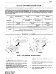
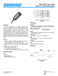
1
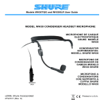
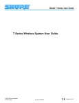
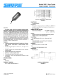
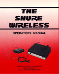
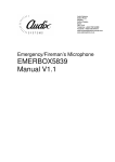
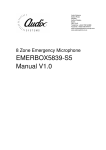
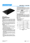
Shure Brothers Incorporated 222 Hartrey Avenue Evanston IL 60202-3696 U.S.A. Model WH10 Dynamic Headset Microphone The WH10 is supplied in three configurations: • The WH10 is supplied with its cable terminating in a rightangle 1/4-inch phone plug for use with Shure Headset Wireless Microphone Systems, or any unbalanced microphone input. • The WH10TQG is supplied with its cable terminating in a miniature four-pin female Tini “Q-G” connector for direct connection to a Shure L11, LX1, EC11, EC1, T1, or similar Body-Pack Wireless Microphone Transmitters.** • The WH10XLR is supplied with its cable terminating in a three-pin male XLR connector with a convenient detachable belt clip. **For use with Shure W10BT, L1 or other transmitters, contact the Shure Wireless Customer Services Department. GENERAL The Shure Model WH10 is a dynamic headset microphone intended for use in applications where light weight, maximum mobility, and high-quality voice pickup are absolute necessities. These include such diverse applications as auctioneers, aerobics instructors, and square dance callers. Additionally, the WH10 is an optimum choice for automatic speech recognition, voice communications, and voice annotation applications where hands-free operation is desired. The WH10 has a cardioid unidirectional pickup pattern that provides isolation from ambient noise and from adjacent sound sources such as machinery, air-moving equipment, musical instruments, loudspeakers and other talkers. Its clarity in close-talk operation combined with a high sound pressure level capability make the WH10 an excellent choice for all mobile voice situations. The WH10’s dynamic cartridge incorporates a carefully shaped frequency response and the Shure voice-frequency presence peak. When used with Shure Body-Pack Transmitters, the performance of the WH10 closely resembles the finest conventional vocal microphones. The microphone’s equalization tailors the low-frequency response to resemble the proximity effect of larger vocal microphones. The cardioid (unidirectional) pickup pattern of the WH10 discriminates against sounds coming from the sides and rear, permitting higher gain-before-feedback and use under noisy conditions without loss or masking of vocals. Its wide frequency response, low RF susceptibility and reliable operation at temperature and humidity extremes make the WH10 suitable for virtually any vocal application. The WH10 is small, extra-lightweight, rugged and reliable. A comfortable adjustable elastic headband* holds securely for active microphone users. The headband and gooseneck length are both adjustable to accommodate any head size or shape, and the microphone can be adjusted so that it faces the corner of the talker’s mouth. The microphone consists of two assemblies: the headband-wireframe, and the microphone-gooseneck-cable. Copyright 1996, Shure Brothers Incorporated 27A2970 (PK) A supplied acoustic foam windscreen can be used when needed to minimize breath sounds and popping, or wind noise in outdoor applications. Features • Extra lightweight headband stays secure and unobtrusive while worn, prevents user fatigue • Response comparable to high-quality conventional handheld vocal microphones • Smooth, natural frequency response • Optimum sound pickup in side-of-mouth position minimizes breath and popping noises • Close-talk operation and unidirectional polar pattern isolates talker from ambient sounds, provides effective noise reduction • High input clipping level eliminates overload distortion • Headband length and flexible gooseneck adjustable for maximum ease in positioning • Supplied acoustic foam windscreen • Reliable at temperature and humidity extremes • Extra-strong small-diameter attached microphone cable resists breakage SPECIFICATIONS Type Dynamic, Close-Talking Frequency Response (at 8 mm [5/16 in.]) 50 to 15,000 Hz (see Figure 1) +10 0 –10 20 50 100 200 500 1,000 2,000 5,000 10,000 20,000 TYPICAL FREQUENCY RESPONSE FIGURE 1 *CROAKIES is a trademark of Life Link International Inc. Shure patent pending Printed in U.S.A. Net Weight (including connector) WH10: 60.1 g (2.12 oz) WH10TQG: 63.5 g (2.24 oz) WH10XLR: 91.9 g (3.24 oz) Polar Pattern Cardioid (unidirectional) response—uniform with frequency, symmetrical about axis (see Figure 2) 180o 150o Certification 150o 120o Conforms to European Union directives, eligible to bear CE marking; meets European Union EMC Immunity Requirements (EN 50 082-1, 1992); RF radiated (IEC 801-3); ESD (IEC 801-2); EFT (IEC 801-4). 120o 90o 90o MICROPHONE PARTS The WH10 consists of the following parts (see Figure 3). –20 dB –15 dB 60o 60o –10 dB –5 dB 30o 30o WIREFRAME 0 500 Hz 1000 Hz 4000 Hz CABLE TYPICAL POLAR PATTERNS FIGURE 2 ELASTIC HEADBAND Impedance Microphone rating impedance is 150 ohms (200 ohms actual) Output Level (close-talked* at 1,000 Hz) Open Circuit Voltage –47.0 db (4.5 mV) (0 dB = 1 V/100 µbar) Power Level –66.0 dB (0 dB = 1 mW/10 µbar) PLASTIC HOUSING MICROPHONE CARTRIDGE GOOSENECK *At 12.5 mm (1/2 inch). Hum Sensitivity 38.4 dB equivalent SPL in a 1 millioersted field Polarity WH10 as a wired microphone: Positive sound pressure on diaphragm produces positive voltage on tip with respect to sleeve (ground) of microphone output phone plug connector WH10, WH10TQG used with Shure Wireless Systems: 1/ -inch Phone Jack Receiver Outputs: Positive sound 4 pressure on diaphragm produces positive voltage on tip of receiver output connector. 3-pin XLR Receiver Outputs: Positive sound pressure on diaphragm produces positive voltage on pins 2 with respect to pin 3 of low-impedance output connector, and on tip of Aux output connector WH10XLR as a wired microphone: Positive sound pressure on diaphragm produces positive voltage on pin 2 with respect to pin 3 of microphone output XLR connector Environmental Conditions Operating Temperatures: –18° to 60°C (0° to 140°F) Storage Temperatures: –40° to 74°C (–40° to 165°F) Humidity: 0 to 95% Cable Attached 1.22 m (4 ft), small-diameter, shielded, PVC-jacketed (WH10: single-conductor; WH10TQG, WH10XLR: two-conductor) Cable Connector WH10: Right-angle 1/4-inch phone plug WH10TQG: Miniature four-pin female XLR (Switchcraft Tini “Q-G” TA4F) WH10XLR: Three-pin female XLR with detachable belt clip Construction Black thermoplastic housing; stainless steel grille; blackTEFLON-coated steel wireframe; rubber-clad steel gooseneck; rubber/nylon elastic headband MICROPHONE PARTS FIGURE 3 1. Microphone Cartridge and Gooseneck: The miniature gooseneck provides flexibility for proper microphone placement. 2. Wireframe: The U-shaped wireframe supports the gooseneck, microphone and cable assembly, and, by wrapping it over the ears and around the back of the head, maintains the microphone position. 3. Housing: The plastic housing secures the microphonegooseneck, cable assembly, and wireframe. Its construction enables the gooseneck and wireframe to be adjusted for optimum microphone position. 4. Elastic Headband: This adjustable headband holds the wireframe and other components securely in place. It is adjustable for maximum comfort and security. 5. Cable and Connector Assembly: The cable extends from the plastic housing to the cable connector, and is secured to the wireframe by a small plastic cable retainer. The thindiameter, shielded cable is terminated in either a rightangle phone plug (WH10), four-pin miniature female Tini “Q-G” connector (WH10TQG), or three-pin female XLR connector with detachable belt clip (WH10XLR). ASSEMBLING THE HEADSET MICROPHONE 1. Attach the wireframe-headband assembly to the plastic housing by snapping the exposed right-hand section of the wireframe into the housing (see Figure 4) so that the microphone-boom assembly is on the right side of the user’s head. 2. Attach the cable retainer to the wireframe to provide a strain relief for the microphone cable. See Figure 3. 2 A ATTACHING THE WIREFRAME FIGURE 4 3. Place the microphone on the user’s head so that the wireframe and elastic band are horizontal across the back of the head, with the elastic headband below the wireframe and the white “SHURE” outward (Figure 5). Note that the elastic headband can be positioned above or below the wireframe; comfort and convenience will dictate the user’s choice. B ADJUSTING THE WIREFRAME FIGURE 7 7. Readjust the position of the elastic band along the wireframe if necessary (step 4). 8. IMPORTANT: For maximum gain before feedback, position the gooseneck so that the microphone grille (silver side) is within 25 mm (1 inch) of the right corner of the mouth. Then bend the gooseneck until the microphone grille faces the right corner of the mouth. 9. Use the spring-loaded clothing clip to secure the microphone cable to the user’s clothing. 10.If breath noise or “popping” is audible over the sound system, install the supplied pop screen. OPERATION Connect the WH10 to the microphone input of the wireless microphone transmitter, or microphone mixer or amplifier. When using the WH10, remember that it is a dynamic (selfpowered) microphone. Dynamic microphones inherently have lower outputs than condenser microphones; in wireless applications especially, the transmitter gain must be increased to compensate for the WH10’s lower output. ELASTIC HEADBAND The elastic headband holding the wireframe securely against the head can be removed from the wireframe and hand-washed in a mild soapy water solution. To remove the headband from the wireframe assembly for washing, follow these steps. 1. Remove the microphone cable retainer from the wireframe. 2. Slide the elastic headband along the wireframe and off the left side of the wireframe (the right end of the wireframe is blocked by the plastic housing). 3. Wash the headband and allow to dry thoroughly. 4. Slide the headband over the left side of the wireframe and around the wireframe to its original position. Replace the cable in the plastic retainer. Note that the CROAKIES elastic headband supplied with the WH10 is not a standard size; CROAKIES headbands purchased in stores are too long for this application. WEARING THE MICROPHONE FIGURE 5 4. Adjust the tension of the elastic headband across the back of the head by sliding it up or down the ends of the wireframe. Note that the band holds the wireframe securely against the back and sides of the head, at the same time preventing excessive head pressure from the wireframe. The maximum amount of travel is approximately 25 mm (1 inch). See Figure 6. (photo) ELASTIC HEADBAND ADJUSTMENT FIGURE 6 5. If the plastic housing does not lie flush along the user’s cheek, or if the headset feels extremely loose or uncomfortably tight, carefully bend the sides of the wireframe to make it tighter or looser around the head (see Figure 7A). 6. The ends of the wireframe should fit comfortably over and in front of the ears. Careful bending of the wireframe (see Figure 7B) can achieve this result. 3 REPLACEMENT PARTS Cable Connector (for WH10TQG only) . . . . . . . . . . WA330 Connector Belt Clip (forWH10XLR only) . . . . . . . RK200BC Black Elastic Headband . . . . . . . . . . . . . . . . . . . . . . . . RK319 Black Elastic Headband and Wireframe . . . . . . . . . . RK314 Microphone, Cable and 1/4-inch Connector Assembly (for WH10 only) . . . . . . . . . . . . . . . . . . . . . . RK315 Microphone, Cable and TA4F Tini “Q-G” Connector Assembly (for WH10TQG only) . . . . . . . . . . . . . . . . . RK317 Microphone, Cable and XLR Connector Assembly (for WH10XLR only) . . . . . . . . . . . . . . . . . . RK316 Black Windscreens (2) and Clothing Clip . . . . . RK318WS For additional service or parts information, please contact Shure’s Service department at 1-800-516-2525. Outside the United States, please contact your Authorized Shure Service Center. MODEL WH10 SLEEVE TIP SHIELD WHITE RED OR WHITE SHIELD 1 2 SHIELD MODEL WH10XLR RED 3 BLACK BLACK CARTRIDGE MODEL WH10TQG RED 1 3 4 SHIELD 2 WIRING DIAGRAMS FIGURE 9 4 BLACK