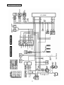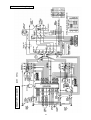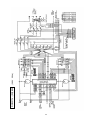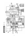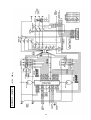
1
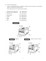
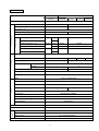
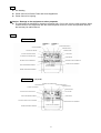
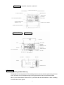
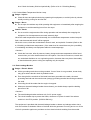
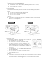
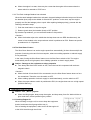
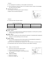
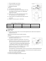
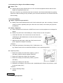
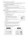
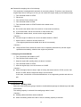
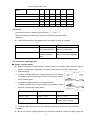
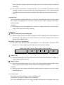
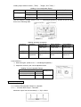
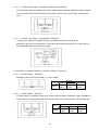
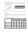
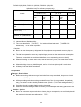
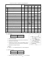
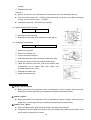
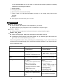
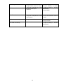
’ Table of Contents ’ Water-cooled 4 Cycle Diesel Engine 1. Safety Guidelines 2. Specifications 3. Use 4. Parts 5. Equipment 5-1. ECO Welding (DGW311DM only) 5-2. Monitor Lamp 5-3. Earth Leakage Breaker 5-4. Slow-Down 6. Initialization and Pre-check 6-1. Checking Engine Oil 6-2. Checking Coolant/Water 6-3. Checking Fuel 6-4. Checking Fuel, Engine Oil, and water Leakage 6-5. Checking Battery 7. Operation 7-1. Initializing/Preparation 7-2. Stopping Generator/Welder 8. Welding Operation 8-1. Selection – Welding Cable 8-2. Polarity 8-3. Connection – Welding Cable 8-4. Duty Cycle 8-5. Welding 9. Generator Operation 9-1. Output Range 9-2. Output Limitation 9-3. Operation 10. Simultaneous Use of Welding and Generating 11. Checking and Maintenance 12. Long-term Storage 13. Troubleshooting 14. Engine Wiring Diagram 15. Generator Wiring Diagram Page 2 5 6 6 7 7 8 9 11 11 11 12 13 14 14 14 14 16 16 16 17 17 18 18 19 19 21 22 23 24 27 28 30 31 Introduction Thank you for purchasing Shindaiwa Sound Proof Diesel Engine Generator/Welder. z This user manual was created to ensure the safe operation of this equipment. Therefore, the manufacturer of this equipment strongly recommends that the user follow the instructions herein, to avoid unnecessary accidents and repairs. z Please operate this equipment after thoroughly reviewing and understanding the contents of this manual. z Please attach this manual, if the equipment will be sub-leased. z Please store this manual near the equipment for easy reference. Following convention will be used throughout the manual to indicate the degree of cautions. Danger Can cause severe injuries or death. Caution <Caution> Can cause minor injuries or damage to the equipment or other properties. Other types of caution z Even some of the items noted in Caution items and follow all the safety guidelines. 1 may lead to severe injuries. Please read all 1. Safety Guidelines Danger : Suffocation from exhaust fume z Exhaust fume from the engine contains many elements harmful to human. Do not operate this equipment in poorly ventilated area, such as inside a room or in a tunnel. Danger : Electric Shock z Do not touch the output terminals during operation. z Do not insert metal objects (such as pin or wire) into plug-in receptacles. z Do not touch wiring or electric parts inside the equipment during operation. z Before connecting or disconnecting a load cable from output terminals, always turn the circuit breaker to OFF position. z Before connecting or disconnecting a welding cable from output terminals, stop the engine, and remove the engine key. z Before performing any equipment check or maintenance, stop the engine, and remove the engine key. A person performing the check or maintenance should always keep the key. Danger : Burns z Do not open the radiator cap while operating this equipment or immediately after stopping the equipment, to avoid sustaining burns from hot vapor. Danger : Injuries z Close all doors and place locks during operating this equipment, to avoid injuries by unintentionally touching cooling fan and fan belt. Caution : Suffocation from exhaust fume z Do not point the exhaust fume toward pedestrians or building. Caution : Suffocation from welding fume z Be sure to wear a fume proof mask in operation, because welding fume contains poisonous gas and dust. Pay attention to the airflow direction and sufficient ventilation also in order to prevent from inhaling the fume. Caution : Injuries to eyes and skin z Be sure to wear spark protection glass(es), long-sleeve shirts, gloves, etc. in order to protect eyes and skin from harmful spark in welding. z Battery fluid contains diluted sulfuric acid. Avoid contact with eyes, skin or on clothing. If the acid comes in contact, especially with eyes, flush with a lot of water, and contact to your physician immediately. 2 Caution : Electric shock z Do not flush water onto the equipment nor operate it in the rain. Caution : Explosion z When the liquid level is below the LOWER level, never use the equipment nor recharge the battery. z Battery may emit some combustible gas, so keep it away from fire and sparks. Caution : Fire z The equipment uses Diesel fuel as a fuel. When refueling, always stop the engine and keep away from fire. Moreover, always wait until the engine cools down before refueling. z Always wipe any drip of Diesel fuel or lubrication oil. Do not use this equipment when a leak is found. Repair the equipment before use. z Temperature around muffler and exhaust can get extremely high. Keep any inflammable items (such as fuel, gas, paint, etc.) away from the equipment. z Keep any inflammable items and easily burning items away from the place in welding, because welding splashes spatters. z Always operate this equipment on flat surface and, at least 1 meter away from any objects (wall, box, etc.). z Do not connect AC output to any indoor wiring. z Always wait until the equipment cools down, before placing any covering materials for storage. Caution : Burns z Do not touch the engine and muffler during operation and immediately after stopping the equipment, for the temperature can reach extremely high. z When checking engine oil or changing oil, always stop the engine, and wait until the engine cools down. If you open either the oil gauge or the oil filter cap during operation, hot oil may cause some injury. z Be sure to wear leather gloves, apron, shoe covers, eye protection glass(es) (mask), safety shoes, safety cap, and long sleeve shirts, because welding splashes spatters. Caution : Injuries z When lifting the equipment, always use a lift hook. Do not lift a handle, for it may cause equipment to drop due to handle breaking off. z Always place the equipment on a flat and stable surface, to keep the equipment from sliding. Be sure to lock the wheels for the wheeled models. z When starting the engine, turn off the connected equipment and set the circuit breaker to OFF position. z Do not move the equipment during operation. z When performing equipment check and maintenance, always stop the engine. z Do not operate the equipment, if the equipment is being modified or if the parts are removed. 3 Location of Warning labels When the warning labels become unreadable or damaged, place new labels on the appropriate locations, as specified in the following figure. When ordering the label, use the following part numbers. Suffocation from exhaust fume (No. 19402-00194 ) Suffocation from welding fume (No. 19402-00195 ) Electric shock (No. 19402-00192 ) Electric shock (No. 19402-00193 ) Injuries (No. 19402-00199 ) Burns (No. 19402-00201 ) Burns (No. 19402-00200 ) Fire (No. 19402-00166 ) DGW311DM DGW311L DGW311L -(W)220B 4 -(W)380A, -(W)400A, -(W)415A 2. Specifications Model DGW311DM DGW311L -(W)220B Generating Method -(W)220B Rated Current (A) 280 260 Rated Voltage (V) 31.2 30.4 (min ) 3600 3000 MAX 85 Current Adj. Range (A) Welding Rod Current Adj. Range (A) Welding Rod Welding Rod 30-160 ECO 2.0-4.0 (Ф ) Single (Ф ) Current Adj. Range (A) Dual 85-310 45-310 35-280 2.6-6.0 2.0-6.0 2.0-6.0 45-160 2.0-4.0 (Ф ) Phase 3-Phase/1-Phase AC Generator Rated Voltage (V) 220/110 Frequency (Hz) 380/220 400/230 60 Rated Output (kVA) Rated Speed -1 50 3-Phase 10 1-Phase (min ) Power Factor 6 8 3600 3000 3-Phase: 0.8 / 1-Phase: 1.0 Rating Continuous Model Yanmar: 3TNE68-USW2 Type Vertical, Water-cooled 4-Cycle Diesel Engine Displacement (L) Rated Output (kW(PS)/min-1 ) 0.784 15.1(20.5)/3600 Fuel 12.9(17.5)/3000 Diesel Fuel(ASTM No.2-D) or Equivalent Lubricant Oil API Class CD or Higher Lubrication Oil Volume (L) 3.5 Cooling Water Volume (L) 3.1 Starting Method Starter Motor Battery 46B24L Fuel Tank Capacity (L) 37 Length (mm) Width 1428 (Bonnet Length 1293) (mm) 700 Height (mm) Dry Weight -(W)415A 50 -1 No Load Voltage (V) Output Change Welding Generator Rated Speed Engine -(W)400A Brushless, Rotating Field, Synchronous AC Generator Duty Cycle (%) Dimension -(W)380A 760 (870 with wheels) (kg) 370 (380 with wheels) 5 415/240 3. Use z Arc Welding z Power Source for Electric Tools and Home Appliances z Power Source for Lighting Caution : Damage to the equipment or other properties z The equipment is designed for the above purposes only. Do not use it for the other purpose. When it will be used for the equipment with the microcomputer control or for the ultra-precision devices, the load may be malfunctioned. 4. Parts DGW311DM CURRENT ADJUSTMENT DIAL A CURRENT ADJUSTMENT DIAL B SLOW-DOWN SWITCH CIRCUIT BREAKER STARTER SWITCH MONITOR LAMP 3-PHASE VOLT METER OUTPUT SELECTOR SWITCH FUEL GAUGE 1-PHASE OUTPUT RECEPTACLE HOUR METER WELDING OUTPUT TERMINAL A WELDING OUTPUT TERMINAL B 1-PHASE OUTPUT TERMINAL EARTH GROUNDING TERMINAL 3-PHASE/1-PHASE OUTPUT TERMINAL BONNET GROUNDING TERMINAL DGW311L -(W)220B CURRENT ADJUSTMENT DIAL CIRCUIT BREAKER SLOW-DOWN SWITCH STARTER SWITCH 3-PHASE VOLT METER MONITOR LAMP 1-PHASE OUTPUT RECEPTACLE FUEL GAUGE EARTH GROUNDING TERMINAL HOUR METER 3-PHASE/1-PHASE OUTPUT TERMINAL WELDING OUTPUT TERMINAL 1-PHASE OUTPUT TERMINAL BONNE GROUNDING TERMINAL 6 DGW311L -(W)380A, -(W)400A, -(W)415A CURRENT ADJUSTMENT DIAL CIRCUIT BREAKER SLOW-DOWN SWITCH 3-PHASE VOLT METER STARTER SWITCH MONITOR LAMP FUEL GAUGE EARTH GROUNDING TERMINAL HOUR METER 3-PHASE/1-PHASE OUTPUT TERMINAL (U,V, W,O) WELDING OUTPUT TERMINAL BONNET GROUNDING TERMINAL DGW311DM DGW311L SIDE DOOR AIR CLEANER FUSE RADIATOR OIL PLUG, ENGINE OIL FILLER OIL GAUGE BATTERY RESERVOIR TANK FUEL LEVER/STRAINER OIL FILTER OIL DRAIN PLUG FUEL INLET WATER/COOLANT DRAIN PLUG FUEL DRAIN PLUG MUFFLER LIFTING LUG HANDLE HANDLE EXHAUST OUTLET TOP PLATE 5. Equipment 5-1 ECO Welding (DGW311DM only) The equipment is incorporated in ECO welding features that are aimed at performing the lower noise, the lower fuel consumption and the lower gas emission than conventional models. When you turn the selector switch to ECO, you will be able to weld with Max. 4.0mm welding rod at the Slow-Down speed. 7 <Caution> z When welding is performed, do not turn the output selector switch, which causes the burnout of the switch. z ECO is designed for welding only. The circuit breaker trips when ECO is used for AC power supply. 5-2 Monitor Lamp The equipment is equipped with monitoring function of oil pressure, battery charge and water/coolant Temperature. When it is started by the starter switch from STOP to RUN OIL PRESSURE MONITOR LAMP under normal condition, Oil Pressure and Battery lamps will BATTERY CHARGE MONITOR LAMP flash, and then the lamps will go off, immediately after the COOLANT/WATER TEMPERATURE MONITOR LAMP engine starts. When abnormality is detected either in water temperature or in oil pressure, the corresponding monitor lamp will flash, and the automatic shutoff shall be engaged to the engine. When the automatic shutoff is engaged, turn the starter switch to STOP position, and then restart the engine. In the event the automatic shutoff is engaged next time, check all parts of the corresponding alarm. 5-2.1 Oil Pressure Monitor Lamp Danger : Injuries z Close all doors and place locks during operating this equipment, to avoid injuries by unintentionally touching cooling fan and fan belt. Caution : Burns z Do not touch the engine and muffler during operation and immediately after stopping the equipment, for the temperature can reach extremely high. z When checking engine oil, always stop the engine, and wait until the engine cools down. If you open either the oil gauge or the oil filter cap during operation, hot oil may cause some injury. When the engine oil pressure drops during operation, the oil pressure monitor lamp will flash, and the automatic shutoff will be engaged. When this occurs, check the engine oil level, and replenish to the maximum level if needed. <Caution> z The engine oil pressure monitor cannot detect the degradation of engine oil itself. Please check the engine oil periodically, and change if needed. (Refer to No. 11. Maintenance.) 5-2.2 Battery Charge Monitor Lamp When the battery is unable to be charged during operation, the battery charge monitor lamp will flash and the automatic shutoff will be engaged. In the event it will happen, consult with the authorized distributor or our engineering section. <Caution> z The battery charge monitor cannot detect the degradation of battery life nor the battery fluid 8 level. Check the battery fluid level periodically. (Refer to No. 6-5 Checking Battery) 5-2.3 Coolant/Water Temperature Monitor Lamp Danger : Injuries z Close all doors and place locks during operating this equipment, to avoid injuries by unintentionally touching cooling fan and fan belt. Danger : Burns z Do not open the radiator cap while operating this equipment or immediately after stopping the equipment, to avoid sustaining burns from hot vapor. Caution : Burns z Do not touch the engine and muffler during operation and immediately after stopping the equipment, for the temperature can reach extremely high. When the water temperature rises abnormally, the coolant/water temperature monitor lamp will flash, and the automatic shutoff will be engaged. When this occurs, check the coolant/water reservoir tank, and replenish if needed. (Refer to No. 6-2 Checking coolant/water temperature.) If the water level is normal there may be a possibility of overloading and always use equipment within the rated amperage. <Caution> z Check the fuse next, after oil pressure, battery charge and water temperature will be found normal when you have checked them in the first place. If the fuse is burned out, consult with our authorized distributor or our engineering section, because there may be an abnormality of electric/electronic parts or wiring and repairing may be required. 5-3. Earth Leakage Breaker Danger : Electric Shock z All the grounding terminals must be grounded. If one of them is not grounded, human body may get a serious electric shock by leaked current. z Even though all the terminals of the loads have been grounded to the earth, the earth grounding terminal and the outer bonnet (canopy) grounding terminal should be grounded to the earth. z Grounding should be made after the engine is stopped. z Whenever the earth leakage breaker has activated, you should always repair the leaking place first of all. <Caution> z The earth leakage breaker activates only for AC power supply. z The circuit breaker trips to protect the loads, whenever AC power is used if the selector switch is in the ECO position. (DGW311DM only) The equipment is provided with the earth leakage breaker to detect any leakage arisen due to such the troubles as insulation failure of the load while the generator is running and to cut off the circuit for protection against any accident such as electrical shock resulting from the trouble. 9 The specifications of the earth leakage breaker : z Rated Sensitive Current: 30mA (or below) (Grounding resistance: 500 z Sensitive time: Within 0.1second or below) 5-3.1 Grounding Work The qualified electrician should perform the grounding work of the following 3 points (500 or below). z The earth grounding terminal in the output terminals z The Outer Bonnet (Canopy) of the generator z The Outer Bonnet of the load <Caution> z In the event you cannot ground the generator to the earth, consult with the authorized distributor or our engineering section. DGW311DM DGW311L EARTH GROUNDING TERMINAL EARTH GROUNDING TERMINAL BONNET GROUNDING TERMINAL BONNET GROUNDING TERMINAL GROUNDING ROD GROUNDING ROD 5-3.2 Operation Check Before operating the generator, check always if the device can work. RESET BUTTON EARTH LEAKAGE INDICATION LAMP Turn the starter switch from STOP to Run. Turn (Push-up) the circuit breaker (lever) to ON position. Push the test button. (When the button is pushed, the earth leakage indication lamp turns ON and the circuit breaker is positioned in the middle of ON and OFF positions, the device can TEST BUTTON work normal.) Push the reset button. (The earth leakage indication lamp (red) turns OFF subsequently.) Turn (push down) the circuit breaker (lever) to OFF position. Restore the switch to STOP. <Caution> z In the event you cannot complete every step of the above procedure to the end, the device is out of order. Consult with our authorized distributor or our engineering section to repair. 10 z When the engine is to start, there may be a case that the engine will not start unless the starter switch is restored to STOP once. 5-3.3 The Earth Leakage Breaker has activated When the earth leakage breaker has activated, the earth leakage indication lamp turns ON and the breaker (lever) trips to the middle of ON and OFF positions. In the case, stop the engine promptly and find the leakage point to repair. After repairing leakage point(s), proceed with the following restoration steps. Push the reset button or stop the engine. Restore (push down) the breaker (lever) to OFF position. By the above procedures, you can reset the breaker to ON position. <Caution> z When the breaker trips to the middle but the lamp does not turn RED simultaneously, the cause is Over-loaded or the output selector switch is positioned to ECO. Restore as per the procedures No. 9-3 Operation. 5-4 The Slow-Down Feature The Slow-Down feature is to set the engine speed low automatically (in about 8 seconds)for the purpose of reducing noise and fuel consumption, whenever welding operation or electric supply is not performed. In the case of using the Slow-Down feature, turn the Slow-Down switch to ON. The engine automatically moves to high speed, when welding operation or electric supply starts. Caution : Damage to the equipment or other properties z Turn always the Slow-Down switch to OFF, when the load is incorporated with a electromagnetic switch. <Caution> z When the load of less than 0.5A is connected to use, the Slow-Down feature does not function sometimes. Therefore, turn the switch to OFF. z When welding operation or electric supply is used intermittently, turn the switch to OFF. z When the output selector switch is positioned to ECO, the engine does not turn to high speed. (DGW311DM only) 6. Initialization and Pre-check Caution : Fire Burns Injuries z When checking engine, always stop the engine, and keep away from fire. Wait until the engine cools down, before performing any checks. OIL GAUGE (YELLOW) 6-1 Checking Engine Oil OIL FILLER When checking for engine oil, be sure to keep the equipment leveled, and insert the oil gauge all the way in. Prior to starting the equipment, make sure to fill the engine oil to the HIGH level through the oil inlet. SIDE DOOR 11 OIL PLUG (YELLOW) <Caution> z If the equipment is not leveled, you cannot obtain accurate oil level. z Do not overfill (over H line) the engine oil. The excessive volume of engine oil may damage the engine (inside the cylinders) Selecting proper engine oil Use the engine oil for Diesel engine in proper viscosity, in compliance with the ambient temperature. UPPER LIMIT (H) REQUIRE LEVEL LOWER LIMIT (L) <Caution> z Use the API class CD grade or higher. Viscosity and Temperature Temperature Over +20 +10 - +20 -10 - +40 Viscosity SAE30 SAE20 SAE10W/30 6-2 Checking Coolant/Water Danger : Injuries z Close all doors and place locks during operating this equipment, to avoid injuries by unintentionally touching cooling fan and fan belt. Danger : Burns z Do not open the radiator cap while operating this equipment or immediately after stopping the equipment, to avoid sustaining burns from hot vapor. Caution : Burns z Do not touch the engine and muffler during operation and immediately after stopping the equipment, for the temperature can reach extremely high. Check to see if the coolant/water level is between FULL and LOW levels in the reservoir tank. If the coolant/water is below the LOW level, fill the tank and the radiator accordingly. 6-2.1 Filling to the Reservoir Tank Take out the reservoir tank to remove the cap. Fill up the reservoir tank to the FULL level. SIDE DOOR CAP Install the cap back and tighten, and reinstall the tank to the equipment. 6-2.2 Filling to the Radiator RESERVOIR TANK Remove the top plate. Remove the radiator cap. 12 Fill up the radiator up to the top. TOP PLATE Install the cap back and tighten. Reinstall the top plate. <Caution> z Use soft water, such as tap water. RADIATOR CAP z If the ambient temperature is near freezing, use Long WATER FILLER Life Coolant (LLC) (30% mixture LLC is filled when shipped from factory). z Mixture ratio of the coolant should be between 30 to 45%, depending on the outside temperature. z Use the same LLC in identical mixture ratio to the resRESERVOIR TANK ervoir tank. z Replace LLC at every year or 1000 hours. Mixture Ratio (for reference only): Lowest Ambient -15 -20 Temperature Mixture Ratio 30% 35% -30 45% 6-3 Checking Fuel Caution : Fire z Always wipe any drip of fuel. Do not use this equipment when a leak is found. Repair the equipment before use. Check for the fuel level in the tank. Add if necessary. <Caution> z Use Diesel fuel, ASTM D975 No.2-D in the event ambient temperature reaches down to -5 . TANK CAP z The engine is designed to use either No.1-D or No.2-D Diesel fuel. However, for better economy, use No. 2-D Diesel Fuel whenever possible. At the temperature less than -7 (20F), No.2-D fuel may pose operating problems (see “Cold Weather Operation” which follows). At colder tem- FUEL INTAKE FUEL STRAIN NET peratures, use No.1-D fuel (if available) or use a “winterized” No.2-D (a blend of No.1-D and No.2-D). This blended fuel is usually called No.2-D also, but can be used in colder temperatures than No.2-D fuel, which has not, been “winterized”. Check with the services stations operator to be sure you can get the properly blended fuel. z Always use the Diesel fuel strainer. z Fill the fuel tank slightly less than the FULL tank. 13 6-4 Checking Fuel, Engine Oil and Water Leakage Caution : Fire z Always wipe any drip of Diesel fuel or oil. Do not use this equipment when a leak is found. Repair the equipment before use. Be sure to check for any fuel leak at the hose connection, and oil and coolant/water by opening side doors. When checking for any fuel leak, open a fuel lever and be sure to close the fuel lever after checking. 6-5 Checking Battery Caution : Injuries to eyes and skin z Battery fluid contains diluted sulfuric acid. Avoid contact with eyes, skin or clothing. If the acid comes in contact, especially with eyes, flush with a lot of water, and contact your physician immediately. Caution : Explosion z When the liquid level is below the LOWER level, never use the equipment nor recharge the battery. z Battery may emit some combustible gas, so keep it away from fire and sparks. Check the fluid level. If the level is near or lower than the TERMINAL LOWER level, add distilled water until the fluid level reaches the UPPER level. UPPER LEVEL Make sure that the battery cables are firmly secured to the posts. Tighten the clamps if necessary. LOWER LEVEL <Caution> z Check the hydrometer of the battery fluid. If it falls below 1.23, the battery requires recharging. Please consult with our authorized distributor or our engineering section. INS-CAP Replacing battery - TERMINAL + TERMINAL Remove the clamp and cable from negative (-) post in the battery. (Remove always negative side first) Remove the hold-down clamp from the battery. Remove the clamp and cable from positive (+) post in HOLD-DOWN CLAMP the battery. BATTERY Remove the battery from the seat. Reinstall a new battery in the reverse order. (Install always the cable to the positive (+) post in the new battery first.) <Caution> z Use the following battery. 46B24L 7. Operation 7-1 Initializing/Preparation 14 Danger : Suffocation from exhaust fume z Exhaust fume from the engine contains many elements harmful to human. Do not operate this equipment in poorly ventilated area, such as inside a room or in a tunnel. Caution : Suffocation from exhaust fume z Do not point the exhaust fume toward pedestrians or building. Caution : Fire z Temperature around muffler and exhaust can get extremely high. Keep any inflammable items (such as fuel, gas, paint, etc.) away from the equipment. z Always operate this equipment on flat surface and, at least 1 meter away from any objects (wall, box, etc.) Caution : Injuries z Always place the equipment on flat and stable surface, to keep the equipment from sliding. Be sure to lock the wheels for the wheeled models. z When starting the engine, turn off the connected equipment and set the circuit breaker to OFF position. Turn the circuit breaker to OFF position. Turn the fuel lever to OPEN. Turn the Slow-Down switch to ON. FUEL LEVER When the temperature is below 5 turn the starter switch to PREHEAT. The preheating lamp flashes 15 CLOSE seconds. The lamp comes off when the PREHEAT finOPEN ishes. Turn the starter switch to START to start the engine by the starter motor. <Caution> z Do not drive the starter motor for more than 15 seconds successively. z If you need to restart, wait for 30 seconds or more before retry. Release the starter switch, as soon as the engine is started. <Caution> z Once the engine is started, do not turn the starter switch to START. Make sure the frequency to the monitor on the control panel. Keep the engine idle for about 5 minutes. DGW311DM DGW311L CIRCUIT BREAKER CIRCUIT BREAKER STARTER SWITCH SLOW-DOWN SWITCH STARTER SWITCH SLOW-DOWN SWITCH PREHEAT LAMP 15 PREHEAT LAMP Restart after stopping due to fuel shortage This equipment is equipped with automatic air vacuuming feature. Therefore, even though the engine stops due to running out of fuel, you can restart the engine easily by the following steps. Turn the starter switch to STOP. Fill the fuel. Turn the Slow-Down switch to ON. Turn the starter switch to RUN. Turn the starter switch to START and drive the starter motor. <Caution> z Do not drive the starter motor for more than 15 seconds successively. z If you need restart, wait for 30 seconds or more before retry. Release the starter switch, as soon as the engine started. <Caution> z Once the engine is started, do not turn the starter switch to START. Wait for about 1 minute to vacuum the air out. (The engine speed becomes stable when the air is extracted.) <Caution> z Keep the Slow-Down switch ON unit the air is completely extracted out (unit the engine speed becomes stable), otherwise the engine may disorder. 7-2 Stopping Generator/Welder Turn (Push down) the breaker to OFF. Turn the Slow-Down switch to ON. Keep the engine idle (cooling down) for about 5 minutes. Turn the starter switch to STOP. After the engine stops, turn the fuel lever to CLOSE. <Caution> z When the engine does not stop in spite of turning the starter switch to STOP, turn the fuel lever to CLOSE, then the engine will stop in a few minutes. In this case, consult with our authorized distributor or our engineering section and ask to repair. 8. Welding Operation 8-1 Selection – Welding Cable Select the cable with proper gauge, based on the allowable amperage and distance per the table shown below. The welding capacity is reduced if the small gauge cable is used. <Caution> z Welding cables should be used unstrained. z When the welding cables are used in swirl, the welding capacity is reduced. 16 Welding Current Size of Cable (Unit: mm2) Return Length 20m 30m 40m 60m 80m 100m 300A 30 38 50 80 100 125 250A 22 30 38 60 80 100 200A 22 30 30 50 60 80 150A 22 22 22 38 50 60 100A 22 22 22 30 30 38 8-2 Polarity There are two kinds of welding output terminals, and Select the polarity according to the operation, referring to the table below. <Caution> z Follow the instruction of the welding rods, the polarity of which is specified. Application Connection Normal Polarity General Welding, such as construction Plus to the Earth (Material) Minus to holder (Rod) Reverse Polarity Thin Plate, Build up Welding, Stainless Steel Plus to holder (Rod) Minus to the Earth (Material) 8-3 Connection – Welding Cable Danger : Electric Shock z Before connecting or disconnecting a welding cable from welding output terminals, stop the engine, and remove the engine key. A person performing should always keep the key. Stop the engine. WELDING CABLE Connect a welding cable to a crimping terminal and a welding rod holder, and connect the other cable to a crimping terminal WELDING ROD CRIMPING HOLDER TERMINAL and a material holder. Connect the welding cables to the output terminals. In terms of DGW311DM, connect cables to the welding output terminals, referring to the table below. MATERIAL HOLDER ECO (Single) Single Dual Welding Rod 2.0 – 4.0 Welding Rod 2.6 – 6.0 Welding Rod 2.0 – 4.0 Welding Output Terminal A Welding Output Terminal A Welding Output Terminal A and Welding Output Terminal B Close the output terminal cover, after finishing connections, and fix the cover with bolts. <Caution> z Be sure to crimp a crimping terminal to a cable and connect the cable to welding output ter17 minal. Otherwise, welding output terminals may burn out by the heat caused by insufficient connections. z Do not use a cable without a crimping terminal. If you use the cable, the insulation is peeled off partly, to bind to an output terminal, the output terminal may burn out by the heat caused by insufficient connections and also a bare part of the cable may touch the bonnet to shortcircuit. 8-4 Duty Cycle Duty cycle means the welding time ratio for 10 minutes. This equipment is the rated duty cycle is 50%, namely, the welding time is 5 minutes or less. Be sure to take 5 minutes recess after 5 minutes welding. <Caution> z The equipment may be damaged due to overheat, if welding more than 5 minutes successively or short time recess after the welding. 8-5 Welding Caution : Suffocation from welding fume z Be sure to wear a fume proof mask in operation, because welding fume contains poisonous gas and dust. Pay attention to the airflow direction and sufficient ventilation also in order to prevent from inhaling the fume. Caution : Injuries to eyes and skin z Be sure to wear spark protection glass(es)(Refer to the table below), long-sleeve shirts, gloves, etc. in order to protect eyes and skin from harmful spark in welding. Standard for Spark Protection Glass (Japan Industrial Standard) Light Shielding Degree No. Welding Current (A) 7 8 9 30-75 10 11 12 76-200 13 201-400 Caution : Fire z Keep any inflammable items and easily burning items away from the place in welding, because welding splashes spatters. Caution : Burns z Be sure to wear leather gloves, apron, shoe covers, eye protection glass(es)(mask), safety shoes, safety cap and long sleeve shirts, because welding splashes spatters. <Caution> z Never turn the output selector switch during welding, because it causes burnout of the switch. (DGW311DM only) 8-5.1 DGW311DM The equipment can be welding by 2 persons simultaneously. Each person can adjust the welding current individually. The current adjustable range by the current adjustable dial depends on the position each of the 18 welding output selector switch ( ECO , Single and Dual Welding Current Adjustable Range Selector Position Current Adjustable Range Single Dual Welding Rod ECO 30-160A 2.0-4.0 Single Use 85-310A 2.6-6.0 Dual Use 45-160A 2.0-4.0 After the engine is started (Refer to No. 7.1 Initializing/Preparation), operate as per the procedures in the following table. CURRENT ADJUSTMENT DIAL A CURRENT ADJUSTMENT DIAL B OUTPUT SELECTOR SWITCH WELDING OUTPUT WELDING OUTPUT TERMINAL B TERMINAL A Procedure Welding Operation Procedure Operation ECO (Single) Welding Rod 2.0- 4.0 Selector Single Welding Welding Rod 2.6- 6.0 ECO Current Adjustment Current Adjust. Dial A SINGLE Current Adjust. Dial A Dual Welding Welding Rod 2.0- 4.0 DUAL Current Adjust. Dial A + B 8-5.2 DGW311L Start the engine. (Refer to No. 7.1 Initializing/Preparation) Adjust the current by the current adjustment dial. Welding Current Adjustable Range Current Adjustable Range Welding Rod 50Hz 60Hz -(W)380A,-(W)400A,-(W)415A 35-280A -(W)220B 45-310A 2.0- 6.0 9. Generator Operation 9-1 Output Range 9-1.1 DGW311DM-(W)220B, DGW311L-(W)220B 9-1.1.1 3-Phase 220V Output – Terminals Maximum output from the terminals (U, V, W) is 10kVA. 19 CURRENT ADJUSTMENT DIAL BREAKER CURRENT ADJUSTMENT 9-1.1.2 1-Phase 220V Output – Terminals (using the terminals only) 1-Phase 220V Output is available, using the 3-phase output terminals. Maximum output available for the one set of the terminals is 6kVA but the total output for the 3 sets is 8kVA, which please note. 9-1.1.3 1-Phase 110V Output – Receptacles & Terminals 1-Phase 110V Output is available through 2 receptacle sets and one terminal set. Maximum output per one receptacle is 1.5kVA and one terminal set is 3kVA. The total output for the receptacles and the terminal set is 6kVA. 9-1.2 DGW311L-(W)380A, DGW311L-(W)400A, DGW311L-(W)415A 9-1.2.1 3-Phase Output – Terminals Maximum output from the terminals (U, V, W) is 10kVA. DGW311L Output voltage -(W)380A -(W)400A -(W)415A 380V 400V 415V 9-1.2.2 1-Phase Output – Terminals 1-Phase Output is available, using the 3-Phase output terminals. Maximum output available for the one set of the terminals is 6kVA but the total output for the 3 sets is 8kVA, which please note. DGW311L Output voltage 20 -(W)380A -(W)400A -(W)415A 380V 400V 415V 9-1.2.3 1-Phase Output – Terminals 1-Phase Output is available, using the 3-Phase output terminals and the other terminal (O). Maximum output available for the one set of terminals is 3kVA but the total output for 3 sets is 8kVA, which please note. DGW311L Output voltage -(W)380A -(W)400A -(W)415A 220V 230V 240V <Caution> z When using 1-Phase output, connect the loads evenly to each terminal set as much as possible. 9-2 Output Limitation Please refer to the following table, because electric tools and home appliances cannot be judged only by the rated output or the power consumption due to the efficiency and characteristic of the components. DGW311DM-(W)220B, DGW311L-(W)220B : Applicable Load (For reference purpose only) Capacity (kW) 1-Phase 110V Loads Receptacle 1 unit Terminal 1 set (60Hz) 1-Phase 220V Receptacle & Terminal Total Terminal 1 set Terminal 3 sets Total 3-Phase 220V Terminal Electric Bulb, Heater, etc. 1.5 3.0 6.0 6.0 8.0 - Electric Tools (Series Motor), etc. 0.7 1.5 3.0 3.0 4.0 - Mercury Bulb (High Power Factor Type) 0.6 1.2 2.4 2.4 3.2 - Submersible Pump, Compressor, etc. (Induction Motor) 0.6 1.2 2.4 2.4 3.2 4.0 21 DGW311L-(W)380A, DGW311L-(W)400A, DGW311L-(W)415A : Applicable Load (For reference purpose only) Capacity (kW) 1-Phase (O & U, V, W) Terminal Terminal 1 set 3 sets Total 3.0 6.0 Loads Electric Bulb, Heater, etc. (50Hz) 1-Phase (U, V, W) Terminal Terminal 1 set 3 sets Total 6.0 8.0 3-Phase (U, V, W) Terminal - Electric Tools (Series Motor), etc. 1.5 3.0 3.0 4.0 - Mercury Bulb (High Power Factor Type) 1.2 2.4 2.4 3.2 - Submersible Pump, Compressor, etc. (Induction Motor) 1.2 2.4 2.4 3.2 4.0 Series Motor: Motor with brush Induction Motor: Brushless Motor The value described is SUMPTION OUTPUT for Induction Motor loads and POWER CON- for the other equipment. <Caution> z Be sure to use the frequency designated in the equipment incorporated in mercury lamp or induction motor. z The load incorporated in motor may require bigger power than the rated power consumption. Therefore, consult with our authorized distributor or our engineering section to clarify. z When connecting 2 or more sets to use, start the load one by one, not to start them simultaneously. z When switching a Mercury bulb ON again, wait for 15 minutes (about) until it cools down. z A Mercury bulb may flicker sometimes. 9-3 Operation Danger : Electric Shock z Before connecting or disconnecting a load cable from output terminals, always turn a circuit breaker to OFF position. z All the grounding terminals must be grounded. If one of them is not grounded, human body may get a serious electric shock by leaked current. (Refer to 5-3 Earth Leakage Breaker z Grounding should be made after the engine is stopped. z Whenever the earth leakage breaker activates, you should repair the leaking place first of all. Caution : Injuries z Be sure to connect to output terminals or insert a plug to a receptacle, after confirming that all the switches in the loads are positioned to 22 OFF . Caution : Damage to the equipment or other properties z In the event using the equipment to computers, microcomputers incorporated loads and precision equipment, there is a possibility for them to be mal-functioned or broken down. <Caution> z Be sure to use the power cord with crimping terminal to connect to output terminals. z Volt meter reads the 3-Phase figures, even if the circuit breaker is positioned to OFF , when the engine is driving. After the engine starts (Refer to 7-1 Initializing/Preparation , operate the equipment as per the following procedures. Turn off the power switch in the load, and then turn the circuit breaker to OFF . Connect the load to the output terminals or receptacles. Close the output terminal cover, after finishing connections and fix the cover with bolts. Turn the circuit breaker to ON . When finishing the load operation, always turn the circuit breaker to OFF The Circuit Breaker Caution : Injuries z Be sure to turn off the power switch in the load when turning the circuit breaker to ON , when the circuit breaker has activated. When the electric supply exceeds the rated output (overload), the circuit breaker activates to trip off in order to shut off the circuit. When the load in operation stops, check the breaker. When the circuit breaker is positioned intermediary ON and OFF , check if the earth leakage indication lamp turns ON or not. In the case the lamp turning ON, refer to 5-3 Earth Leakage Breaker . In the case the lamp NOT turning ON, follow the next procedures to restore the circuit breaker. Turn off all the power switches in the loads. Turn (Push) down the circuit breaker to OFF once and then turn (push) up the circuit breaker to ON <Caution> z Take care for overload, referring to 9-2 Output Limitation z When the output selector switch is positioned to ECO and AC power is used, the circuit breaker trips off to shut down the circuit. Stop using AC power and follow the above procedures to restore the circuit breaker. (DGW311DM only) 10. Simultaneous Use of Welding and Generating The circuit breaker reacts on the AC power supply circuit only. In the simultaneous use of welding and generating, there sometimes happens overload to the engine. Refer to the following table and limit the AC power use. DGW311DM-(W)220B, DGW311L-(W)220B : Limitation of AC Power Supply in the simultaneous use of welding and generating (60Hz) 23 Welding Output AC Power Output Welding Rod/Current 3-Pase Power use only 1-Phase Power Use only 2.0mm/50A or below 9.5kVA or below 7.6kVA or below 2.6mm/80A 8.6kVA or below 6.8kVA or below 3.2mm/120A 7.2kVA or below 5.7kVA or below 4.0mm ( 2.0mmx2)/170A 5.2kVA or below 4.1kVA or below 5.0mm ( 2.6mmx2)/220A 6.0mm ( 3.2mmx2)/280A 3.0kVA or below 0kVA or below 2.4kVA or below 0kVA or below ( ) indicates 2-Persons Dual Use. (DGW311DM only) <Caution> z The simultaneous use of ECO welding and AC power is not available. (DGW311DM only) DGW311L-(W)380A, DGW311L-(W)400A, DGW311L-(W)415A : Limitation of AC Power Supply in the simultaneous use of welding and generating (50Hz) Welding Output AC Power Output Welding Rod/Current 3-Pase Power use only 1-Phase Power Use only 2.0mm/50A or below 8.5kVA or below 6.8kVA or below 2.6mm/80A 7.6kVA or below 6.0kVA or below 3.2mm/120A 6.2kVA or below 4.9kVA or below 4.0mm/170A 4.2kVA or below 3.3kVA or below 5.0mm/220A 6.0mm/260A 2.0kVA or below 0kVA or below 1.6kVA or below 0kVA or below 11. Checking and Maintenance Danger : Electric Shock Injuries z Before performing any equipment check or maintenance, stop the engine, and remove engine key. A person performing the maintenance should always keep the key. Caution : Fire Burns z When checking the engine, always stop the engine, and keep away from fire. Wait until the engine cools down, before performing any checks. To optimize the use of this equipment, we recommend the periodical equipment checks and maintenance based on the following matrix. <Caution> z The authorized technicians should perform all checking and maintenance work, except for the pre-startup checks. z Request for the maintenance item with mark to the authorized distributor or our engi- neering section. z This table only covers the simple checks and maintenance for the engine. For more detailed guide, please refer to the User’s Manual for the engine. z Always use our genuine replacement parts. 24 1 Use the hour meter as a guide for the operating time. Checking Time Checking Items Startup Check Every Every Every At 1000 hrs 200hrs 400hrs 50hrs Check and Supply Fuel 2 Check and Supply Engine Oil 3 Engine Oil Change 1st 2 or 4 Oil Filter Change 1st after nd 2 or 5 Check/Add Water/Coolant 6 Water/Coolant Change 7 Clean/Change Fuel Filter 8 Drain Water from Fuel Tank Every 2000 hrs nd after or one year 9 10 Check Leakage Fuel Oil Check/Add Water Battery 11 Clean/Change Air Cleaner Element 12 Adjust Tension V-Belt 13 Clean Radiator Fin 14 15 Change Hose Fuel Radiator Change Vibration-Absorbing Rubber Adjust Engine Valve Clearance 16 Check/Adjust Injection Nozzle 17 Check/Adjust Injection Pump (Clean) (change) (Clean) nd 2 or (change) Water 1st after or 2 years (Adjust) 11.1 Oil Change First Time 2nd or after (Adjust) 50 hour mark Every 200 hours SIDE DOOR Remove the oil plug. Loosen the oil drain plug and allow the oil to drain fully. OIL FILLER Reinstall the oil drain plug. Checking the oil level by the oil level gauge, add oil OIL PLUG (YELLOW) into the oil filler to fill up to the max level. (3.5 liter Max) OIL DRAIN PLUG Reinstall the oil plug hand tight. <Caution> z Refer to 6-1 Checking Engine Oil 11.2 Oil Filter Change First Time nd 2 or after to select engine oil. 50 hour mark Every 200 hours Drain the engine oil fully, as describe in 25 11-1 Oil Change Loosen and remove the oil filter, using an oil filter wrench. OIL GAUGE (YELLOW) Smear a little engine oil on the rubber gasket of a new filter. Screw the new filter into place and tighten it by hand until the gasket contact the seat. Then, give it additional OIL FILTER 1.1/4 Turn to seat the filter, using an filter wrench. GASKET Supply oil and install the filler cap. <Caution> z If an oil filter wrench is not available, contact our authorized distributor or our engineering section. z Oil Filter Part No.: 119305-35151 (Yanmar) 11.3 Cleaning/Changing Air Filter Element Clean Every 200 hours Replace Every 400 hours Unfasten clips in the cleaner cap and remove the air AIR CLEANER cleaner cap. Unscrew the wing bolt and remove the air filter element. SIDE DOOR Clean or replace the air filter element, and reinstall it in reverse order. <Caution> z Clean more frequently, if used in dusty environment. CLIP ELEMENT z Air Filter Element Part No. 121465-12510 (Yanmar) WING BOLT How to clean air filter element CLEANER <If the element has dried contaminants> It may be cleaned by blowing compressed air from the inside. <If the element has carbon or oil> It should be replaced to a new one. 11.4 Cleaning/Changing Fuel Filter Clean Every 200 hours Replace FUEL LEVER Every 400 hours CLOSE Turn the fuel line valve lever to CLOSE . Unscrew the retaining ring by turning counterclockwise, and RETAINING RING OPEN CUP remove the cup and fuel filter element. Discard any dust or water inside the cup, and clean the filter element by blowing compressed air. (or replace, if necessary) (When you replace the filter element, be sure to replace a o-ring 26 as well) Reassemble it back. <Caution> z Be sure to check for any contaminants on the packing, whenever reinstalling the cup. z Turn the fuel line valve lever no leak, turn the fuel line valve OPEN after assembling, and check for any leak. Confirming CLOSE . z Fuel Element Part No.: 124550-55700 (Yanmar) 11.5 Draining Water from Fuel Tank Drain Water Every 200 hours SIDE DOOR Unscrew the fuel drain plug. Reinstall the drain plug, after draining the water entirdy. FUEL DRAIN PLUG WATER DRAIN PLUG 11.6 Changing Coolant/Water Replace Every 1 year or 1000 hours TOP PLATE Remove the top plate. Remove the radiator cap. Loosen the water drain plug. After draining all the water, reinstall the water drain plug. RADIATOR CAP Remove the reservoir tank and replace all the water. WATER FILLER Install the reservoir tank back, and fill the radiator with coolant/water up to radiator filler neck. (Total coolSIDE DOOR ant/water Capacity is 3.1 liter.) Reinstall the radiator cap. CAP Install the top plate back. RESERVOIR TANK 12. Long - Term Storage Danger : Electric Shock z Before performing any equipment check or maintenance, stop the engine, and remove the engine key. A person performing the maintenance should always keep the key. Caution: Injuries z Before performing any equipment check or maintenance, stop the engine, and remove the engine key. A person performing the maintenance should always keep the key. Caution : Fire Burns z When checking engine, always stop the engine, and keep away from fire. z Temperature around muffler and exhaust can get extremely high. Wait until the engine cools down, before performing any checks. 27 If the generator/welder will not be used for more than two months, perform the following maintenance and storage procedures. Remove battery. Change engine oil. Drain fuel from fuel tank and fuel filter. Clean all parts, cover the generator/welder, and keep it in the storage, away from dust and humidity. <Caution> z Recharge the removed battery once a month. 13. Troubleshooting Danger : Electric Shock z Do not operate the equipment, if the equipment or you are wet. z Before performing any equipment check or maintenance, stop the engine. Caution : Injuries z When performing equipment check and maintenance, always stop the engine. Caution : Fire Burns z When checking engine, always stop the engine, and keep away from fire. z Temperature around engine, muffler and exhaust can get extremely high. Wait until the engine cools down, before performing any checks. Follow the guideline below, when performing any troubleshooting. If you cannot resolve the problems by this troubleshooting guide, contact the authorized distributor or our engineering section to request the repair. Symptoms Possible Cause Corrective Actions Starter motor does not start 1. Weak Battery 2. Dead Battery 1. Recharge Battery 2. Replace Battery Engine does not start 1. Fuel lever to CLOSE 2. Insufficient Fuel 3. Water or contaminants in fuel 1. Fuel lever to OPEN 2. Replenish fuel 3. Drain water or clean fuel tank, fuel filter, and water sediments Engine starts, but stalls imme- 1. Insufficient oil diately 2. Insufficient coolant/water 1. Replenish oil 2. Replenish coolant/water Welding Arc is weak 1. Turn to SINGLE or SPEED 2. Turn the dial clockwise Excessive Welding Arc 1. Output selector switch is to ECO or DUAL 2. Wrong current adjustment dial setting 3. Poor contacts of cables 4. Improper Cable Diameter RATED 5. Insufficient connection to material 6. Dual Use 7. Engine output is down 3. Connect securely 4. Change cables according to Selection – Welding Cable 5. Connect securely 6. Stop using AC Power 7. Keep 50% duty cycle 1. 1. Turn to Output selector switch is to SINGLE or RATED OUTPUT 2. Wrong current adjustment dial position 28 ECO or DUAL 2. Turn the dial counterclockwise No AC output 1. Circuit breaker is to OFF 2. Output selector switch is to ECO 1. Turn to 2. Turn to AC Output is Weak 1. The power consumption of the load exceeds the rated output 2. Dual Use 1. Adjust according to LIMITATION 2. Stop welding Slow-Down does not activate 1. Short circuit of welding cable 2. The power consumption of the load is 0.5A or below 1. Repair the short circuit 2. Turn the Slow-Down switch to OFF Engine does not stop 1. Stop Solenoid disorder 1.Turn the fuel lever to to stop and repair Black and white smoke exhaust from muffler successively 1. Overloaded use 1. Keep the duty cycle 2. Adjust according to LIMITATION 29 ON SINGLE or DUAL OUTPUT CLOSE OUTPUT DGW311DM DGW311L 14. Engine Wiring Diagram 30 (220V 60Hz) 15. Generator Wiring Diagram 31 32 DGW311L - (W)220B (220V 60Hz) 33 DGW311L - (W)380A (380V 50Hz) 34 DGW311L - (W)400A (400V 50Hz) 35 DGW311L - (W)415A (415V 50Hz) Head Office : Telephone : 81-82-849-2220 FAX : 81-82-849-2481