1
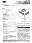
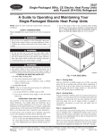
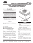
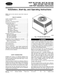
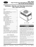
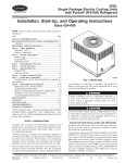
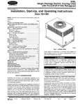
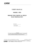
Small Packaged Products
Accessory Crankcase Heaters
Cancels: IlK 582A-18-4
IlK 582A-18-12
5-01
Installation Instructions
PIN CPCRKHTR003A00,
CPCRKHTR004A00
CPCRKHTR005A00,
CPCRKHTR007A00
NOTE:
Read
installation.
This
symbol
the entire
_
instruction
indicates
a change
SAFETY
Installing
and servicing
ous due to system
trained
repair
air conditioning
Untrained
electrical
equipment
can be hazard-
components,
and fuel gases.
personnel
can
coils,
should
the
should
install,
service,
be
safety
perform
basic
maintenance
or cleaning
and replacing
performed
by
information.
trained
filters.
service
This is the safety-alert
When you see this symbol on
manuals,
be alert to the potential
Understand
the signal
48GXJ583A/PY2P-S
50GX/702A/PA2P-S
50JXJ602A/PH2P-B
50JZ/602B (FACTORY INSTALLED ON 042-_0)
48GP/583B
50GL/702B
UNIT SIZE
024
240 V
CPCRKHTR004A00
functions
030
CPCRKHTR004A00
NA
All other
036
CPCRKHTROO4AO0
CPCRKHTROO5AO0
042
048
CPCRKHTROO4AO0
CPCRKHTR004A00
CPCRKHTROOSAO0
CPCRKHTR005A00
060
CPCRKHTROO4AO0
CPCRKHTROO5AO0
personnel.
When working
on air conditioning
equipment,
observe precautions
in the literature,
on tags, and on labels attached
to the unit.
Recognize
Table 1--Accessory Crankcase Heater Usage
See Below for Units Applicable
or
equipment.
personnel
operations
starting
since the last issue.
air conditioning
and qualified
such as cleaning
before
CONSIDERATIONS
pressures,
Only
manual
words
symbol
z_ -
the unit and in instructions
for personal
injury.
or
DANGER,
WARNING,
Table 2--Accessory Crankcase Heater Usage
See Below for Units Applicable
and CAU
TION. These words are used with the safety alert symbol
DANGER identifies
the most serious hazards which will result in severe
personal
could
injury
result
identify
injury
or
death.
WARNING
in personal
unsafe
practices
or product
suggestions
injury
which
and property
which
signifies
or death.
would
NOTE
in enhanced
which
Have
all
safety
codes.
Wear
a fire extinguisher
safety
UNIT SIZE
240 V
460 V
CPCRKHTR007A00
NA
personal
024
CPCRKHTR007A00
NA
is used to highlight
030
CPCRKHTR007A00
036
CPCRKHTR007A00
CPCRKHTROO3AO0
O42
CPCRKHTR007A00
CPCRKHTROO3AO0
O48
CPCRKHTROCAA00
CPCRKHTROO5AO0
060
CPCRKHTR007A00
CPCRKHTR003A00
is used
in minor
installation,
to
reliability,
or operation.
Follow
48GS/582A/PY1 P-S
50GS/701 A/PAt P-B
018
CAUTION
result
danlage.
will result
a hazard
460 V
NA
glasses
and
work
gloves.
available.
NA
INTRODUCTION
These instructions
case
Heater
on
Cooling/Gas
cover the installation
of an Accessory
Electric
Cooling,
Heat
Pump
and
Ideating
_)
units.
DESCRIPTION
The
accessory
crankcase
oil to reduce
proper
heater
refrigerant
compressor
CrankElectric
AND
warms
migration
lubrication.
50JSi601A/PHIP-B (FACTORY INSTALLED ON 036)
UNIT SIZE
240 V
460V
USAGE
the compressor
in the crankcase
Refer
to Tables
Table 3--Accessory Crankcase Heater Usage
See Below for Units Applicable
crankcase
018
CPCRKRTR007A00
HA
and ensure
024
030
CPCRKHTR007A00
CPCRKHTR007A00
NA
NA
036
CPCRKHTR007A00
CPCRKHTR003A00
042
048
CPCRKHTR004A00
CPCRKHTR004A00
CPCRKHTR005A00
CPCRKHTR005A00
060
CPCRKHTR004A00
CPCRKHTR005A00
1, 2 and 3.
INSTALLATION
4. Spread
pressor
1. Turn
off
gas
supply
power
supply.
Lockout
Tag,
electric
2. Install
3. Remove
Fig.
access
panel
(if
applicable)
first,
then
disconnect
plate.
5. Fasten
crankcase
base
and control
box. (See
6. Route
heater firmly
crankcase
heater.
heater
around
compressor
in place with fastening
(See
com-
mounting
clip provided
with
Fig. 1.1
heater leads
the path of the compressor
1.)
and wrap
2-in. above
(See Fig. l.I
the crankcase
for compressor
heater arms
approximately
into unit control
box, following
leads. (See Fig. 1.)
Manufacturer reserves the right to discontinue, or change at any time, specifications or designs without notice and without incurring obligations.
Book 1
4
PC 101
Catalog No. 534-80055
Printedin U.S.A.
Form 48/50-102SI
Pg 1
501
Replaces: 48GS,GX-3SI
( NOTE:
TOP
CONDENSER
COMPRESSOR
SECTION
ROUTE WIRES
AS SHC_'N
NOT
SHOWN
)
INDOOR FAN MOTOR
CRANKCASE
HEATER
CONTROL
/_HEATER
BOX
CLIP
C01015
Fig. l_Typical
Crankcase Heater Installation
CH
c
c
--
BLK---_
LEGEND
C
CH
--<_)
Compressor Contactor
Crankcase Heater
Marked Terminal
C01014
Fig. 2--Crankcase
7. Connect
one black
11, and connect
terminal
black
lead
contactor
to compressor
terminal
9. Replace
contactor
access
10. Turn on main
panel.
power,
then (if applicable)
gas supply.
21. (See Fig. 2.)
8. Attach green
control box.
Copyright
lead to the compressor
other
Heater Wiring
crankcase
heater ground
lead to ground
screw
in
2001 Carder Corporation
Manufacturer
reserves
PC 101
the right to discontinue,
Catalog No. 534-80055
582a1812
or change at any time, specifications
Printed in U.S.A.
or designs
Form 48/50-102Sl
without
notice and without
Pg 2
5-01
incurring
obligations.
Replaces:
48GS,GX-3SI