1
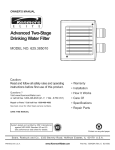
OWNERS
MANUAL
MODEL NO.
625.349290
CAUTION
Read All Safety
Guides Before
You Start to
Install Your
Dispensing
System
-- HOW TO INSTALL-
HOW IT WORKS-
CARE OF-
-- SPECIFICATIONS
--
-- REPAIR PARTS-SAVE THIS MANUAL
Sears, Roebuck and Coo, Chicago,
PRINTED
IN U S A
IL 60684 U.S.A.
TABLE OF CONTENTS
PAGE NO,
Safety Guides ........................................
What Does The Dispensing
System Do .......
PAGE NO.
3
Electrical
Wiring
3-4
Solutions
to Feed and Feed Rate .............
............................
5
Controls
Put The System Together ........................
6
Keeping The System in Working
Locating and Solution
7
Dimensions
Tools and Materials
Installing
Needed
.........................
Injecting
................
......................................
SEAl'S
FULL
8-10
11
12-14
and Features ...........................
and Specifications
14
Order _.....
.................
15-17
17
Repair Parts ...................................
18-19
sOWT ON
O SPENS,NG
SYSTEM
ONE YEAR WARRANTY
ON SOLUTION
DISPENSING
SYSTEM
For one year from the date of purchase,
when this Solution
Dispensing
System
is installed
and maintained
according
to our instructions,
Sears will
repair
defects
in
material
or workmanship
in the Solution
Dispensing
System, free of charge.
WARRANTY
SERVICE
IS AVAILABLE
SERVICE CENTER IN THE UNITED
duct is in use in tile United States.
This warranty
gives you specific
from state to state.
Sears,
Roebuck
and Co.
INSTALLATION
STATES.
legal rights,
CONTACTING
This
warranty
THE NEAREST
applies
only
and you may have other
Dept. 731-CR-W,
If you want your solution
dispensing
system
wilt arrange for a prompt, quality installation
SEARS
BY SIMPLY
Sears Tower,
Chicago,
while
rights
SEARS
this
which
pro-
vary
IL 60684
professionally
installed, talk to your Sears Salesman.
by Sears Authorized
Installers
POLICY
All installation
labor arranged
by Sears shall be
performed
in a neat, workmanlike
manner
in
accordance
with generally
accepted
trade pracrices. Further, all installations
shall comply with
all local laws, codes, regulations
and ordinances.
Customer
shall also be protected,
during installation, by insurance
relating to Property
Damage,
Workman's
Compensation
and Public Liability
SEARS
INSTALLATION
He
WARRANTY
In addition to any war ranty extended to you on the
Sears merchandise
involved,
which
warranty
becomes
effective
the date the merchandise
is
installed,
should the workmanship
of any Sears
arranged
installation
prove faulty within one year,
Sears will, upon notice
from you, cause such
faults to be corrected
at no additional
cost to you.
I SAFETY GUnDES
A Read all steps, guides and rules carefully
before installing and using your new Solution
A Check with your local public works department for plumbing,
electric and sanitation
codes. You must follow their guides as you
install your dispensing system.
Dispensing System. Follow all steps exactly to
correctly install. Failure to follow them could
cause personal injury or property damage.
Reading this book will also help you to get all
of the benefits from your dispensing system.
A Be sure the electric outlet for the solution pump
is grounded the right way to protect the user
from injury or possible fatal shock.
A Protect the Solution Dispensing System and
tubing from freezing. Damage from freezing
voids the warranty.
When you see this sign in the book,
followed
exactly.
A something
could
be damaged,
or someone
hurt if theguideisnot
WHAT DOES YOUR SOLUTJO
Water
is one of the best soSvents known
to man, It
dissolves
and picks
up part of everything
it
touches_ As water filters through
the earth and
rock strata, it absorbs minerals
such as calcium,
magnesium,
iron and hydrogen
sulfide
(rotten
metal taste and causes many other problems_ The
2 main forms of iron are FERROUS and FERRIC
Ferrous
or
CLEAR
WATER
iron
is the
most
egg odor), If the water is not treated and improved
in some way, it may be useless, Feeding solutions
into the water is a good way to treat the water.
common
type. Water with ferrous
iron is clear
when taken from a fauceL After standing
for 15 to
30 minutes,
the water turns to a yellow or brown
color.
Your Sears Solution Dispensing
System treats the
following
kinds of water problems,
DO NOT USE
THE SYSTEM
IN AN ATTEMPT
TO PURIFY
POLLUTED
WATER.
Ferric or RED WATER iron is rusty or brown as it's
taken from the faucet,
After standing
for awhile
the iron will settle out.
(1) IRON WATER -- MAX. 20 PPM
(2) HYDROGEN
SULFIDE
WATER
PPM
BACTERIAL
iron is another
kind of ferric iron.
When this water is taken from a faucet and left
--
MAX,
20
(3) ACID WATER -- 4.0 pH and ABOVE.
(4)ACID
WATER
AND
IRON
BACTERIA,
HYDROGEN
SULFIDE, OR HIGH AMOUNTS
OF IRON -- MAX. 20 PPM TOTAL
The following
briefly
water problems
(1)
IRON
elements
problems
on almost
WATER
--
and 4.0 pH.
describes
each
of these
One of the
most
common
for several
clumps.
hours,
it forms
slimy,
stringy,
TREATING
IRON WATER -- Adding chlorine
to
the water and then filtering
it is a good way to
remove both the ferrous and ferric forms of iron,
Chlorine also kills iron bacteria. A Sears Solution
Dispensing
System
feeds
household
laundry
bleach into the water system ahead of the pressure
tank, The chlorine
in the bleach oxidizes the iron.
it touches, gives water a
Then a Sears Automatic
Clarifier
and a Sears
(NOTE: BACTERIAL IRON and IRON BACTERIA are the same )
3
in the earth's crust, iron causes water
all over the world. It makes rust stains
everything
standing
mud-like
WHAT
YOUR SOLUT OI
water softener,
installed
on the outlet
side of the
and over 70 it's basic (alkaline)
If the pH is less
than 7 0, the water contains too much acid Acid
pressure tank, filters and softens the water If you
do not like a remaining
chlorine taste, Sears has
taste and odor filters to remove it,
water corrodes galvanized and copper plumbing,
and makes red or blue-green
stains on plumbing
fixtures, dishes and clothes
It often addsa bitter
(2) HYDROGEN
SULFIDE WATER -- Many water
supplies
corrtain
hydrogen
sulfide
(sulphur)
Dissolved hydrogen
sulfide gas, in underground
water, gives the water a bad taste and/or odor
similar to rotten eggs This water is often corrosive and may stain sinks and faucets
taste to the water because of dissolved
iron caused by the corroding
copper
or
Sears Neutralizer
Compound,
Stock
No 4234475, fed into the water by a Sears Solution
Dispensing
System raises the pH to 7.0making
it
neutral
corrode
A Sears Solution
Dispensing
System
feeding
chlorine,
oxidizes
hydrogen
sulfide
and other
sulfides
making them tasteless and odorless
If
the water has both hydrogen
sulfide and iron,
Sears urges you to install an Automatic
Clarifier
along with the dispensing
system InstallaSears
Taste and Odor filter to remove chlorine
taste
and odor
(4) ACID
DROGEN
Neutralized,
or stain
the
water
will
no longer
WATER, AND IRON BACTERIA,
SULFIDE
OR HIGH AMOUNTS
HYOF
IRON -- A mixture of Sears Neutralizing
Compound, Stock No 42-34475, and chlorine
treats
acid water that also has iron, bacteria or hydrogen sulfide
The neutralizer
raises the pH of the
water to help the chlorine
oxidize
the iron or
(3) ACID WATER-Water is measured
on a pH
scale of 0to 14. Water with a pH of 7 0 is neutral,
hydrogen sulfide
Oxidized, the iron or hydrogen
sulfide is filtered with a Sears Automatic
Clarifier.
I WATER SYSTEM TESTS
HAS
YOUR
WATER
SUPPLY
HAD
CHEMICAL
If you have a well water
system,
look at the
pressure
gauge to find the water pressure.
Call
your local water department
if you have city water.
They will tell you what the water pressure is where
,ou live
ANALYSIS?
A chemical
analysis
tells you the
types and amounts
of elements
in the water,
These facts determine
what size and type of water
treating
equipment
is needed, and how to correctly use it If your water needs analysis, call or
write your nearest Sears store for help_
CHECK
YOUR
WATER
SUPPLY
KEEP A RECORD OF YOUR
WATER SYSTEM FACTS
SYSTEM
PRESSURE
For your solution
dispensing
system
to work right, water system pressure must be less
than 75 psi If pressure
is over 75 psi, buy and
install
a pressure
reducing
valve or adjust the
pump pressure switch
NOTE: If daytime pressure
is 60 psi or more, pressure during the night hours
may go over 75 psi.
System Pressure (psi)
__
Hardness __ (gpg)
Iron Content (parts per million) __
Tastes, odors or other
i
4
pH __
TREATING WELL WATER
PRE-TREATING
PRIVATE
WELL
SYSTEMS
,&CAUTION:
This much
chlorine,
at one time,
could exhaust
the activated
carbon in a taste
HAVING IRON BACTERIA
-- Before you put the
dispensing
system together
and install it, chlorinate the well if it contains
million (ppm) of bacterial
steps.
and
more than 10 parts per
iron. Use the following
odor
3 Open
1_ For each 50 gallons of water in the well, pour 1
quart of ordinary
household
bleach into it. On
have
a taste
and
odor
all faucets
of water into the well to
to the water level
in the
house,
1 at a time.
Close each faucet when you can smell the
bleach•
Keep the water system closed for a
minimum
of 2 hours
If possible,
keep closed
overnight
some wells, you can pour the bleach through the
breather pipe. On others, you may have to remove
the well seal
NOTE: You will probably
have to estimate
how
much water is in the well and use atrial and error
or else ask a qualified
If you
2. Pour several gallons
flush the bleach down
NOTE: If you don't chlorinate
the well, you may
have iron in your water for up to 2 months after
you install the solution
dispensing
system
method of treatment,
technician.
filter°
filter in your water system,
by pass it to keep
the chlorine
out while doing this pre4reating.
4. After 2 hours, or the next morning,
open all
faucets and let the water run until clear and the
bleach odor is gone
well
TOOLS AND MATERIALS
TOOLS
NEEDED
-- You will need common
and
MATERIALS
-- Depending
on where and how you
install the Solution
Dispensing
System (page 7),
you may have all the things needed. Things not
included with the systemthatyoumayneedare••
cross point (Phillips)
screw drivers, a slip-joint
pliers, tape measure or rule, and a sharp knife.
Depending
on the kind of pipes you have in your
house, other tools you may need are ....
If you have to install an electrical
outlet (page
11), you will need materials
meeting
electrical
wiring codes,
rWire, outlet box, receptacle,
wire
nuts or tape, etc.
. .for SOLDERED
COPPER
-- tubing
cutter,
propane torch, solid-core
solder, paste flux, emery
cloth, sandpaper
or steel wool
.....for THREADED
pipe wrenches,
compound
. • Jf you will pump solution
directly
into the well
(see pages 7 and 8) you may need more tubing
Read the note under step 2 on page 8
PIPE-- hacksaw or pipe cutter,
pipe threading
tool, pipe joint
• . •for CPVC PLASTIC
wrench, solvent cement,
• • •If you will pump solution
into the water system
between
the well pump and pressure
tank (see
-- hacksaw,
adjustable
fine emery cloth.
pages 7 and 10), you may need some of the pipe
fittings shown in FIG. 6, page 10
5
PUT YOUR
DISPENSING
- Take the holding nut off the suction valve and slide
over the end of the tubing. Push the tubing onto the
end tip of the valve as far as it will go, Slide the holding
nut up and tighten with your finger&
1, Fasten the solution pump to the base with 4 nylon
screws and nuts, as shown
2. Working through the tank fill hole, assemble the
Low Level Indicator to the tank as shown, Positon the
upper window
port so the red indicator
NOTE: If the tubing is cold, dip the end of it in hot
water to make it easier to work with,
is easily seen_
3. Set the reservoir (tank) into the round indent
the base
in
5. From the tubing
included,
cut off about a 33 in,
length, Be sure both ends are square Then connect
this tubing between the solution pump RETURN TO
SUPPLY VALVE and the RETURN bulkhead fitting
on the tank_ Be sure to tighten both holding nuts.
4. Cut a 14" length of tubing and connect to the
suction (bottom) bulkhead fitting on the tank, Use a
sharp knife to cut square. Connect the tubing to the
SUCTION VALVE on the solution pump as follow&
6. Cut a 2 in piece of tubing and, looking at Key No_ 9
on page !8, connect the strainer to the suction bulkhead fitting, inside the tank
NOTE: BE SURE TO CONNECT TO THE SUCTION
VALVE IF CONNECTED
TO THE WRONG VALVE,
THE SYSTEM WILL NOT WORK,
Parts of
Low Level
Indicator
Reservort
(Tank)
Solution
RETURN
Bulkhead
Fitting
Pump "_
SUCTION
Fitting
Nylon
Screw (4) __
Base
/
Nylon
I
Nut (4)
RETURN TO
SUPPLY
VALVE
6
WHERE TO LOCATE YOUR
Locate the system where...
.... IT'S AWAY
......a 115 volt, 60 Hz electrical
nearby. (See page 11)
...good
pump
source
is
A
fresh air flow will cool the solution
motor and carry away solution
fumes.
..... the area is clean
A
power
FROM
DIRECT
SUNLIGHT
DAMAGE
FROM SOLUTIONS,
LEAKS THAT COU LD OCCUR,
LIKELY
DUE TO
IS LEAST
it's close to the solution
injection
point
Read about the 3 ways to inject solution,
below.
and the air is free of dust.
_ .the solution
pump and tank are easy to
reach for servicing
and refilling,
BUT
OUT OF THE REACH OF CHILDREN
PiCK THE BEST WAY TO INJEI
Chlorine
or neutralizer
ways with the solution
feeding is done in 1 of 3
dispensing
system
Read
neutralizer
(_)
or neutralizer
injected
into
Chlorine
or
neutralizer
injected
the
NOTE: In 90 to 95%
System installations,
at some
point between the well pump and pressure
tank (FIG. 2 and FIG 6, page 10).
IMPORTANT:
the solution
When the well pump
feed pump is feeding
For the chlorine
or
blem water. If you have a fast water pumping
system*,
you must install a 42 gallon (or larger)
blending
tank, as shown in FIG. 3, to get the
needed mixing
time. A blending
tank is available
from
Sears,
Stock
No. 42.34028o
alternate
discharge
fitting on the well pump
(FIG. 2 and FIG. 5, page 9)-This
is the best
way to feed neutralizer.
(_)
water..
water
drawing,
most
water
bypasses
the
pressure
tank.. This does not allow enough
time for good solution
mixing to treat the pro-
Chlorine
or neutralizer
injected
right into
the well casing (FIG. 2, below and FIG. 4,
page 8) - This is the best way to feed
chlorine.
Chlorine
the
neutralizer
to work right, it must mix with the
problem
water for a short time. With today's
fast recovery
water
pumps
and direct
fresh
the following
and pick the best way to treat your
water supply..
(#
into
of all Solution
Dispensing
a blending
tank is needed
for proper Solution
mixing° A blending
tank is
helpful in all installations,
but in some (shallow
well, long piping runs, feeding neutralizer
compound only) it could be left out under certain
is running,
chlorine
or
conditions°
Talk
ment for help.
to your
Sears
sales
depart-
To Household
ULC
Water
Filter
CAUTION:
Pressure
Tank
CHLORINE,
INJECTED
)
(_
SOLUTION
INJECTION
INTO
WELL CASING-PAGE 8
THE
(_)
SOLUTION
WELL
PUMPINJECTION
ALTERNATEINTO
CHARGE FITTING -- PAGE 9
THE
DIS-
(_)
SOLUTION
INJECTION
THE WELL PUMP AND
TANK-PAGE 10
BETWEEN
PRESSURE
I From Well
I
INTO THE WATER, MAY SHORTEN
7
THE LIFE OF GASKETS
AND SEALS
IN YOUR WATER SYSTEM
I BLENDING TANK
Pressure
Tank
Tank
Pressure
BLENDING TANK
42 ga! minimum
-- separate inlet & outlet
-- no air bag or diaphragm
BLENDING TANK
42 gal minimum
-- separate inlet & outlet
-- no air bag or diaphragm
' ,ill i
Well I
iI
PRESSURE TANK INSTALLED "ON" THE MAIN
SUPPLY LINE
Pump
Well
I
Well!_I
I
II
CAPTIVE AIR PRESSURE TANK INSTALLED
DISCHARGE SIDE OF WATER PUMP
"ON"
GUXDESTO nNSTALL YOUR
(:_ SOLUTION INJECTION
INTO THE WELL CASING
NOTE: Looking at FIG. 4, put some weight on the
tubing so the injection fitting will stay under water.
Large steel washers(3/8"l.D.)make
good weights.
1. Set the solution dispensing
system in the place
you chose to locate iL See page 7 for guides.
2. Measure for the length of tubing needed to run
from the solution pump discharge fitting down to
the water level in the well The tubing is stiff, so
allow enough length for longer bends. Cut both
ends of the tubing square with a sharp knife..
5. Lower the injection fitting
CAUTION: In cold weather climates, you must
insulate this tubing so it will not freeze.
DO NOT REMOVE THE PLASTIC SLEEVE FROM
THE TIP OF THE INJECTION FITTING. IT IS A
WORKING PART.
NOTE: The system includes 15 ft. of tubing= If more
is needed, look at the parts list on page 19. You can
use a bulkhead fitting (Key #5, page 19) to join
tubing together.
SEE PAGE 11 TO MAKE THE NEEDED
TRICAL CONNECTIONS.
3. Remove the nut from the discharge valve (FIG.
4) on the solution pump. Slide the nut over1 end of
the tubing. Push the tubing onto the tip of the
discharge valve as far as it will gOoThen slide the
holding nut onto the valve and tighten it with your
fingers.
end of the tubing
to the injection
ELEC-
Pump Head
Discharge Fitting
f
NOTE: To prevent siphoning of solution, buy (see
page 19) and install an anti-siphon valve as shown
in FIG. 4. Siphoning of solution may occur when
the solution dispensing system is located above
the injection point fitting.
4. In the same way as in step 3, connect
down into the well
reosure
iWe,
ank
the other
i
Pump
]_
fitting.
Line Weight
injection
8
Fitting_
=J 'v ll,"2 °°
_
Well
GUBDESTO BNSTALL YOUR S
(_)
SOLUTION
INJECTION
INTO
THE ALTERNATE
DISCHARGE
FITTING
ON THE WELL
PUMP
1. Turn off the electrical
power to the well pump
and turn off the gas or electric supply to the water
heater
10. In the same way as in step 9, connect
end of the tubing to the injection
fitting
2. Open a faucet for a few seconds,
water pressure, then close
11. Turn on the electrical
power to the well pump
and open the main water supply
valve
Open
faucets to let air out of the water system,
then
close
to bleed
3. Close the shut-off valve on the main water
close to the pressure tank
off
the other
pipe,
NOTE: If you havea shut-offvalveontheinletside
of the pressure
tank, you don't have to drain
Otherwise,
drain all water from the tank.
12. Check
it
4. Open the drain valve on the well pump, if it has
one, and remove the prime plug Close the drain
valve
your
plumbing
work
13. Turn on the gas or electric
heater and relight the pilot
for leaks
SEE PAGE 11 TO MAKE
TRICAL CONNECTIONS,
supply
THE
to the water
NEEDED
5. Turn a reducer bushing into the prime plug hole to
reduce it to 1/4 in. pipe thread Use teflon tape or pipe
dope on the outside threads
6. Put teflon tape or pipe dope on the threads of
the injection
fitting
and turn it into the reducer
bushing until tight
DO NOTOVERTIGHTEN
DO
NOT REMOVE
THE PLASTIC
SLEEVE
FROM
THE TIP OF THE INJECTION
FITTING
IT IS A
WORKING
PART,
7. Set the solution dispensing
system in the place
you chose to locate it See page 7 for guides
8. Measure for the
from the solution
injection
fitting,
enough length for
the tubing square
length of tubing needed to run
pump discharge
fitting,
to the
The tubing
is stiff, so allow
longer bends Cut both ends of
with a sharp knife
9. Remove the nut from the discharge
valve (FIG
5) on the solution
pump Slide the nut over 1 end
of the tubing.
Push the tubing onto the tip of the
discharge
valve as far as it will go Then slide the
holding
nut onto the valve and tighten it with your
fingers
Pump Head
Discharge Fitting
I
ELEC-
I GUIDES TO
_)
SOLUTION
INJECTION
BETWEEN
THE WELL PUMP AND
1. Turn off the electrical
power to the well pump
and turn off the gas or electric supply to the water
heater,
2. Open a faucet for a few seconds
water pressure, then close
to bleed
3o Close the shut-off valve on the main supply
close to the pressure tank
valve on the well pump,
off
to 1/4 in_ pipe thread.
the threads
7. Put teflon
for the length
SEE PAGE 11 TO MAKE
TRICAL CONNECTIONS.
for leaks.
supply
THE
system
of tubing
NEEDED
with a sharp
ELEC-
Pump Head
Discharge Fitting
TeoF,.,o0
I I
/|
of the
-...___y\
Injection
in the place
needed
to the water
if it has
to run
from the solution
pump discharge
fitting,
to the
injection
fitting. The tubing is stiff, so allow enough
length for longer
bends.
Cut both ends of the
square
work
as shown, to reduce the tee
8. Set the solution
dispensing
you chose to locate it
tubing
plumbing
14. Turn on the gas or electric
heater and relight the pilot.
injection
fitting and turn it into the reducer bushing
until tight. DO NOT OVERTIGHTEN
DO NOT
REMOVE THE PLASTIC
SLEEVE FROM THE TIP
OF THE INJECTION
FITTING
IT IS A WORKING
PART.
9. Measure
your
Use teflon tape or pipe dope on
tape or pipe dope on the threads
the other
12. Turn on the electrical
power to the well pump
and open the main water
supply
valve. Oper
faucets to let air out of the water system, then close
13. Check
pipe
5. Between the well pump and pressure tank, install
ateefittingasshown
in FIG 6 INSTALLTHETEE
AS SHOWN, SO THE INJECTION
FITTING GOES
WITH THE FLOW OF WATER NOT AGAINST
IT
6. Use a reducer bushing
TANK
11. In the same way as in step 9, connect
end of the tubing to the injection
fitting.
NOTE: If you have a shut-off
valve between
the
pressure tank inlet and the place you will install the
injection
point, you do not have to drain water from
the tank Otherwise,
drain all water from the tank.
4. Open the drain
one
PRESSURE
knife.
10. Remove the nut from the discharge
valve (FIG.
6) on the solution
pump. Slide the nut over lendof
the tubing.
Push the tubing onto the tip of the
discharge
valve as far as it will go_ Then slide the
holding
nut onto the valve and tighten it with your
fingers.
10
Fitting
ELECTRICAL
A
WgRRNG GUIDE, €
CAUTION:
DO NOT
TRY TO DO ANY
WIRING
IF YOU DO NOT KNOW
ELECTRICITY.
CALL A GOOD ELECTRICIAN
A
must follow
1. Looking at FIG.7and8or9,
in a duplex,
3-prong,
115
" outlet
Be sure to connect the
the well pump pressure switch
pump
runs only when
Receptacle
local or national
Conduit
installand wire
volt grounded
outlet through
so the solution
the well pump
-_
is on
CAUTION:
Many well pumps work on 230
volts. DO NOT CONNECT
THE SOLUTION
PUMP TOA230VOLTCIRCUIT,
Connectto
only 1 leg of a single
shown in FIG 9.
OUTLET
Wall
CAUTION:
DO NOT DO ANY WIRING
ON
LIVE CIRCUITS
ALWAYS TURN OFF THE
ELECTRICAL
POWER AT THE SOURCE,
NOTE: All wiring
electrical
codes.
,_
115 VOLT
phase 230 volt circuit,
WIRING
as
DIAGRAM
- 115 VOLT
SYSTEM
Duplex. 3-prong
Electrical Outlet
2, Turn on the electrical power at the source DO
NOT plug in the power cord this time. First, fill
the storage tank with solution (page 12).
Solution
Pump
Well
Pump
n Pump
Power Cord
From
115V Power
Source
_'N Pump
Pressure
Switch
115V
WIRING
DIAGRAM
- 230 VOLT
SYSTEM
Solution Pump
Power Cord
L 1 Star
Well
Pump
11
Neutral
L1
L2
230V
Control
Box
or
Pressure
Switch
Solution
Pump
230V
Power
Souse
I RLL THE TANK WnTH
THE
SOLUTION
DISPENSING
SYSTEM
RESER-
FEED CONTROL
VOIR (TANK) HOLDS 15 GALLONS OF SOLUTION.
HOWEVER,
ON THE FIRST FILL, ALLOW SOME
ROOM
IN THE TANK
SO THE SOLUTION
STRENGTH
CAN BE CHANGED
IF NEEDED. DEPENDING ON THE WATER PROBLEM
YOU ARE
3
KNOB
'
TREATING,
FILL THE TANK AND SET THE FEED
RATE AS FOLLOWS.
IRON
AND
-- Remove
HYDROGEN
the reservoir
SULFIDE
TREATMENT
No. 1 settingis for the least solution feed. no 7is for the most,
and no 4 is the mid-point. ALWAYS BE SU RE THE SOLUTION
PUMPIS RUNNING WHEN TURNING THIS KNOB NEVER
ATTEMPT TO TURN THE KNOB WHEN THE PUMP IS OFF.
(tank) cover and fill the tank
with 5 gallons of water and 5 gallons of 5.25% common household bleach (Purex, Clorox, Hilex, etc.)_
1. Plug the pump power cord in and open a nearby
faucet to start the well pump The solution pump
starts to run with the well pump_
2. Turn the feed control knob (FIG 10) to No.. 7.
3. Turn the relief-release
valve (clockwise
only
RELIEF-RELEASE
VALVE OPEN
FIG. 11) to the open position.. Solution is pumped
through the suction tubing, into the pump head, then
returned to the tank (takes 3-5 minutes)..
4. When you See solution returning to the tank (look
through fill hole), close the relief-release valve tur ning
clockwise only_ The pump head is primed and will
begin to pump solution out the discharge. Replace
the tank cover.
SUCTION
5. When the discharge tubing is filled with solution,
turn the feed control knob to No 4 and close the
faucet opened in Step 1.
6. After 24 hours, check
follows.
the chlorine
residual
TO
SUPPLY
as
Adjust the feed control knob and/or the solu-
tion strength
as needed
HOW
CHECK
TO
CHLORINE
1. Open a nearby faucet to start the well pump and
the solution
pump.
2. Follow the guides with the kit and test the water.
A chlorine
residual of 0.2 to 0_6 ppm is ideal
3. If the residual
is over 06 ppm, turn the feed
control
knob (FIG
10) downward
slightly
and
check again in 24 hours. Do this each day until the
residual
stays between
02 and 06. ALSO SEE
THE NOTE FOLLOWING
STEP 4.
RESIDUAL
(FEEDING
BLEACH)
-- It is ideal to feed just
enough chlorine
bleach to get rid of iron and/or
hydrogen
sulfide
However, the amount of these
minerals in your water can change from season to
season, and even from day to day For this reason,
you have to feed slightly
more chlorine
bleach
than needed
This extra bleach sometimes
gives
the water a chlorine
taste and/or odor that some
people
4. If the residual is under 0.2 ppm, turn the feed
control knob (FIG 10) upward slightly and check
again in 24 hours_ Do this each day until the
residual stays between
0.2 and 0_6. Then check
every few days.
dislike.
To have the least chlorine taste and odor and still
remove the iron or hydrogen
sulfide
from the
water, you must maintain
a chlorine
test kit is included with your Solution
System.
solution
DISCHARGE
NOTE:
residual
A
Dispensing
The chlorine
to water mixture
ratio, above
left, is average
You may not be able to maintain
the residual, even with the lowest or highest feed
After installing
the system and feeding
for 24 hours, use the test kit as follows.
rate settings_
12
If so, do the following.
I RLL THE TANK WroTHSOLUT
1. Residual
still
knob at 1 or 2--
above 0.6, and the feed control
Use less chlorine
in the mixture
For example,
use 1 gallon of bleach
gallons of water instead of 1 to 1
for each
1. Opena nearby faucet to start the well pump and
the solution
pump
2. Follow the guides with the kit to test the water
from the opened faucet
3. If the pH level is below7 0, turnthe
feed control
2
2. Residual still below 0,2, and the feed control
knob at6or7-Use more chlorine in the mixture
For example,
use 2 gallons
of bleach
gallon of water instead of 1 to 1
WAClD
WATER
TREATMENT
--
Remove
knob (FIG 10) upward slightly and check again in
24 hours If the pHchecksabove80,
turnthefeed
for each
control
knob downward
slightly and check again
in 24 hours
Do this each day until thepHstays
between 7.0 and 8 0 Then check every few days
the reserNOTE:
voir (tank) cover and fill the tank with 8 gallons of
WARM water. Pour in 80 oz. (10 oz per gallon of
water) of Sears Neutralizing
Compound,
Stock No.
42-34475. Stir until the compound is completely dissolved,
1. Plug the pump
For example, mix 5 oz, of neutralizer
each gallon of water
2. pH below7
HOW
WTREATMENT
IRON
in Step 1_
CHECK
THE
pH
LEVEL
feed rate
compound
in
0, andthefeedcontrolknobat6or7
OF ACID
BACTERIA,
WATER
HYDROGEN
THAT ALSO
HAS
SULFIDE,
OR
(FEEDING
NEUTRALIZER
COMPOUND)
-- The pH level of
acid water is below 7,0 on a scale of 1 to 14, From
7,0 and above, the water is neutral, When feeding
neutralizer,
it is best to keep the pH level between
7.0and80
Atestkitisincluded
with yoursolution
dispensing
system
to make this check. After
installing
the system and feeding
hours, use the test kit as follows.
is
HIGH AMOUNTS
OF IRON -- Begin by filling the
tank with 8 gallons of WARM water, Pour in 80 oz
(10 ozo per gallon of water) of Sears Neutralizer
Compound, Stock No, 42-34475, Stir until the compound is completely
dissolved.
Add 2 gallons of
5.25% common household
bleach (Purex, Clorox,
Hilex, etc ),,
as needed.
TO
mix-
-- Use more neutralizer
compound
in the mixture,
For example,
mix 15 ez, of neutralizer
compound
in each gallon of water_
6. After 24 hours, check the pH level as follows.
Adjust the feed control knob and/or the solution
strength
to water
1.pHabove80,
and the feed control knob at 1 or2
-- Use less neutralizer
compound
in the mixture.
5. When the discharge tubing is filled with solution,
turn the feed control knob to No. 4 and close the
opened
compound
80 pH, even with the lowest or highest
settings
If so, do the following
faucet to start the well pump, The solution pump
starts to run with the well pump.
2. Turn the feed control knob (FIG, 10) to No_ 7_
faucet,
neutralizer
ture ratio (10 oz. compound
per gallon of water)
average
You may not be able to maintaina70to
power cord in and open a nearby
3. Turn the relief-release
valve (clockwise
only
FIG 11) to the open position, Solution is pumped
through the suction tubing, into the pump head, then
returned to the tank (takes 3-5 minutes).
4. When you see solution returning to the tank (look
through fill hole), close the relief-release valve turning
clockwise only. The pump head is primed and will
begin to pump solution out the discharge.
Replace
the tank cover,,
The
solution
ACAUTION:
ALWAYS MIX THE WATER, NEUTRALIZER AND BLEACH
IN THE SAME ORDER AS
ABOVE
1. Plug the pump power cord in and open a nearby
faucet to start the well pump The solution pump
starts to run with the well pump.
2. Turn the feed control knob (FIG. 10) to No. 7
-continued-
for 24
13
FILL THE TANK WnTH
3. Turn
the relief-release
valve
(clockwise
only
FIG. 11, page 12) to the open position_ Solution is
pumped through the suction tubing, into the pump
head, then returned to the tank (takes 3-5 minutes).
4. When you see solution returning to the tank (look
through fill hole), close the relief-release valve turning
clockwise only_ The pump head is primed and will
begin to pump solution out the discharge_
5. When the discharge tubing is filled with solution,
turn the feed control knob to No. 4 and close the
faucet opened in Step 1
6. After 24 hours, check the chlorine
pH following
the guides
on pages
residual
arrd the
12 and l&
CONTROLS AND FEATURES
RELIEF-RELEASE
VALVE -- The solution
ing system will pump solution
having up to 100 psi pressure.
dispens-
into water systems
If the water system
pressure goes over 100 psi, the relief-release
valve
opens to protect
the dispensing
system
from
possible
darnage_ When open, solution
passes
through the relief-release
valve and returns to the
solution
tank instead
of going to the discharge
tubing (FIG,
and solution
12)_ The relief-release
again pumps
into
tubing when
and below.
the water
pressure
valve closes
the discharge
drops
PRIMING
THE
HEAD
--
The relief-release
valve
also makes it easy to pr.ime the pump head= With
the solution
tank full of solution,
and the well
pump and solution
pump running, open the reliefrelease valve (turn clockwise only). When you see
solution
returning
to the tank (look through
fill
hole), close the relief-release
valve. The pump head
is primed and will begin to pump solution
out the
discharge
tubing.
to 100 psi
RELIEF-RELEASE
CLOSED-__
DISCHARGEJ
OPEN j_
NORMAL SOLUTION
FLOW FROM TANK
TO DISCHARGE
TUBING
_
TO
TANK, RELIEFSOLUTION
RETURNS
RELEASE VALVE
OPEN
O_
RETURN
TO
SUPPLY
SUCTION
14
SUCTION
KEEP YOUR DaSPENSUNG
RESERVOIR
(TANK)
SOLUTION
LEVEL
--
REMOVING
After
AND
CLEANING
THE
PUMP
HEAD
installing the solution
dispensing
system, check
the solution
level in the tank daily. Red shows in
CARTRIDGE
VALVES -- Before
the valves, open the relief-release
removing
any of
valve. Be sure to
the Low Level Indicator
when about 5 gallons of
solution remains. After awhile, you will know about
how much solution it uses each day and how often
to refill the tank. ALWAYS REFILL BEFORE THE
remove electric supply, pressure
close valves as required,
from system
SOLUTION LEVEL DROPS TOO LOW, Always mix
the solution in the same ratio as your residual and
pH testing (pages 12, 13, 14) show the need for.
NOTE:
Be sure
to check
the
chlorine
1. Remove suction, discharge
valves from the head_
and return
NOTE: Plug tubing (use pencil
vent loss of solution.
or other tool) to pre-
2. Place valves in a container
and soak for about 15 minutes
residual
and/or pH level every few days to keep the readings
within the limits.
3. Thoroughly
4. Visually
needed.
CHECKING
VALVES
system
THE
PUMP
HEAD
--, If the
solution
pump
is not using
1. Remove
solution,
the solution
2. Open a faucet
solution pump,,
runs,
but the
is returning
inspect
with
with
fresh faucet
vinegar
water,,
and repeat steps 2 and 3 if
5. Put some silicone
grease or vaseline
on the
threads of the fitting_ Then install in the correct
position
in the pump head° Finger tighten,
then
turn another 1/8 to 1/4 turn with a pliers°
do the following:
the well pump
and
6, Connect
the tubing to the fitting
using the
holding
nuL Refer to FIG 1, page 6 for correct
hookup,
3. Look into the tank to see if solution
is returning
to the tank through the top bulkhead fitting. If solution
flush
filled
to supply
CARTRIDGE
tank cover°
to start
and
....
. .a_ Injection
fitting
plugged,
_ressure over 100 psL
or water
SUCTION
system
VALVE
Fitting
take apart here
o .b. Release-relief
valve is leaking
or defective,.
4. Open the relief-release
valve (turn clockwise
only). If solution
does not return to the tank ......
. ,a. Suction
•..b,
Return
valve leaking
to supply
or plugged,
Seat
valve is leaking.
Spring
5. Open the relief-release
valve (turn clockwise
only) if sotution
is returning
but system was not
using solution ....
•..a.
Discharge
DISCHARGE
6. Close the relief-release
close the water fauceL
valve (CLOCKWISE),
7. Remove and clean or replace
tion fitting,
& RETURN TO SUPPLY VALVES
take apart here
valve is leaking.
Ball
Fitting
and
valves or the injecBall
15
Spring
I KEEPYOUR DUSPENSnNG
LUBRICATION
-- At least
every
6 months,
lubricate
the solution
pump as follows:
SHAFT ASSEMBLY
CAM
1. Unplug the electrical power cord,
2. Loosen the set screw in the feed control knob
and remove the knob and bushing,
3. Remove the pump top cover,
4. Clean all the grease from the moving parts and
inspect for wear, damage or corrosion. Replace
parts as needed
5. Lubricate all parts with a premium grease,
NOTE: If you replace any parts, adjust
plate (FIG. 14) as follows:
DRIVE BLOCK
!
! REW
EXTREME REAR
POSITION
rf.......
\.°.v._.w/
_
3. Rotate the shaft assembly until the flat position
on the cam is bearing on the drive plate.
4. Tighten
the adjustment
plate holding
screw
while holding the flat of the cam against the drive
plate.
\
GEARMOTOR
I
Every 6 months,
place a few
drops of spindle oil on the rear rotor bearing (right
behind the fan).
1. Unplug
the power
power
motor
under
lift the
DRIVE PLATE
CAM
THE DIAPHRAGM
on the new diaphragm.
hex nut, then the fiber
ADJUSTMENT
PLATE
--
Place the spacer
washer.
over the
3. Holding the backup gasket in place behind the
diaphragm,
turn the diaphragm
into the drive plate
until the spacer just touches
it. Then tighten
to
align the mounting
holes.
4. Replace the pump head and turn in the 4 screws,
tightening
in a criss-cross
pattern.
5. Plug the power cord in and prime the head using
the guides or] page 14.
cord.
holding
/ oi ojj
1. Turn the diaphragm
to the left (f-") to remove.
Discard the diaphragm,
backup gasket,spacer
and
washer. (see Key No. 18, page 18).
2. Put a few drops of oil or lightly grease the stud
DIAPHRAGM
2. Remove the 4 screws
the housing°
SHAFT ASSEMBLY
y
DIAPHRAGM SPACER
REPLACING
THE
PIVOT
DRIVE BLOCK IN
1. Loosen the adjustment
plate holding
screw.
2. Plug in the power cord and operate motor until
the block-drive
is in the extreme
rear position_
Disconnect
power cord.
CHECK
!
GUIDE SCREW /
the cam and
NOTE: To get at the gear motor, unplug the
cord and remove the screws holding
the
housing to the regulator
housing (located
pump head and at rear of pump). Carefully
regulator
housing up and off_
/HOLDING
the pump head to
3. Move the pump head away from the pump and
inspect
the diaphragm
for cracking,
swelling,
softening or blistering.
If a new diaphragm
is needed, replace it as follows:
CHECK
THE TUBING
-- Check the solution
carry-
ing tubing and fittings
weekly for any signs of
leakage_ if leaking at a holding nut, tighten it 1/8 to
1/4 turn. If it still leaks, disconnect
the tubing, cut
the end square and reconnect
it to the fitting.
-continued-
16
KEEP YOUR D SPENSING
If the dispensing
system is exposed
to the sun,
replace the solution
tubing every6
months.
Replace the tubing yearly if the system is installed
indoors.
CHECK THE INJECTION
FITTING -- The plastic
sleeve on the injection fitting helps to keep it clean
and working_ However, check it every few months
to keep it from plugging.
CLEAN THE STRAINER-Before filling the tank
with solution,
remove the strainer,
remove the
threaded
fitting from the end of the strainer, then
CAUTION:
clean by forcing
strainer..
water
backwards
through
BE SURE
SYSTEM PRESSURE
INJECTION
FITTING.
TO
TURN
BEFORE
OFF
WATER
REMOVING
THE
the
DUMENSBONSAND
Electrical
Voltage
.......
Frequency
.................
Amperage
....................
1 15 AC
60Hz
37
Max. Pumping Rate per
Hour ..................
05 gals. (1 89 Liters)
Max_ Pumping
Rate per
24 Hours ..............
12 gals. (4&4
Liters)
Max. Water System
Press ...................
75 psi (5.27 kg/cm 2)
14-1/2"__
DIA
26"
Reservoir
Capacity
............
29-1!2"
15 gals. (56.8 Liters)
22"
17
l
m
27
26
\
\
\
-N
25---'-
MODEL NO. 625.349290
m
9
I
/
!
16
RETURN
PARTS LiST
KEY
NO.
PART
NUMBER
MODEL
DESCRIPTION
KEY
NO.
PART
NUMBER
NO. 625.349290
DESCRIPTION
:;g
m
1
818405
Float Assembly
19
9006056
2
818399
Pipe, Low Level Indicator
20
813533
Lock Washer
818510
Tank Cap
22
818408
Motor,
4
8800650
Tank,
23
818215
Motor Housing
5
U0812612
24
818285
Regulator
6
818382
Tank Base
25
8800656
Drive
7
811704
Nylon Nut (4 req.)
8
811703
Nylon Screw
26
810545
Spring
9
8800418
27
818227
Top Cover
m
10
814211
28
818258
Bushing
;g
11
8800702
818256
Knob
(#
30
810338
Spare Sleeve
15 Gal. (incl. Cap, Key No. 3)
Bulkhead
Fitting
(2 req.)
(4 req.)
Strainer
Compression
Cartridge
Nut
Valve
discharge,
Kit (incl. 1 each
suction
and return valve)
129
Screw,
12
812318
Head, Relief-Release
31
8800606
13
816342
Head Cover
32
818502
Tubing,
33
818564
Fan
14
L98013_-188
Flat Washer
(4 req.)
15
810036
16
U0816093
Plunger
8800710
Head Assembly
Screw,
#10-32
Assembly
through
17
818544
18
8800470
Power
x 1-3/4 (4 req.)
(incl. Key Nos. 10
16)
Cord Assy.
Diaphragm
Kit
d) Optional item, not included with system.
Not illustrated.
® Motor Replacement - If motor is connected to power
cord by wire nuts, order Motor Replacement Kit. 818_78
8800406
#10-32
x 1/2 (2 req.)
(2 req.)
m
_g
120V, 60 Hz, 10 RPM@
Housing
Block
Injection
Kit, (includes
spring
washer Key No. 26)
(#
Washer
Fitting (incl. Key No. 30)
3/8 in. O.D. x 15 ft.
Anti-Siphon
Valve,
818509
Water Test Kit
818505
Owners
Manual
_g
=4
(#
3/8 in. d)
(F642-5289)
S AI S
OWNERS
MANUAL
SERVICE
MODEL NO.
625.349290
HOW TO ORDER
REPAIR PARTS
Now that you have purchased
your Solution
Dispensing
System,
should a need ever exist for repair parts or service, simply contact
any Sears Service Center and most Sears, Roebuck and Co stores
Be sure to provide all pertinent
facts when you call or visit
The model number of your Solution
Dispensing
rating decal, on the side of the solution
pump
WHEN ORDERING
ING INFORMATION:
---
REPAIR
PARTS,
PART NUMBER
MODEL NUMBER
All parts listed may be ordered
most Sears stores
TELL SEARS YOU
WANT IT INSTALLED
THEN RELAX
ALWAYS
System
is on the
GIVETHEFOLLOW-
-- PART DESCRIPTION
-- NAME OF ITEM
from any Sears Service
Center
and
If the parts you need are not stocked
electronically
transmitted
to a Sears
center for handling
locally,
Repair
When
you can be sure the job is
Sears
arranges
the installation,
your order will be
Parts Distribution
done right We will arrange for professional
workmanship
and
we'll take care of the entire project
What's more, during installation
you get insured protection
against property
damage and also
against accidents
to workmen
All you have to do is talk to your
Sears salesperson
or call your nearest Sears store today for detailed
information
Sears, Roebuck and Co., Chicago, IL 60684 U.S.A.
(F642-5289)
818505 (4/94)