1
38EZG, 38ETG, 38ESG
12, 13, 14 SEER SpMit-System
Air Conditioner
with Puron®
HEATUNG & COOUNG
%isitx__ _.carrier.com
Installation and Start-Up
instructions
NOTE: Read the entire instruction manual be%re starting the
installation
This symbol --> indicates a change since the last issue,
SAFETY
Improper
or
installation,
use
can
distlibutor
installer
when
modit}-ing
for information
codes.
gloves.
Have
extinguisher
Electrical
manuals,
see
which
signal
The qualified
instructions
glasses,
protective
cloth
t\_r brazing
Read
these
clothing,
operations.
instructions
thor=
included
in literature
codes
and National
on the unit
and
for personal
words;
symbol
could
to identify
inju V or
result
or
unsafe
practices
WARNING,
inju V or prodnct
suggestions
and property
which
signifies
inju V or death.
CAUTION
would
damage.
will result
result
NOTE
in enhanced
Run
refrigerant
unnecessary
WARNING
which
3
injury.
DANGER,
death.
in personal
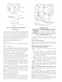
Fig. 1--Models
and
4. Leave
is used
tubes
mrns
some
slack
5. When passing
with RTV
6. Avoid
between
refiigerant
as
possible
structure
and
robes through
or other pliable
direct robing
joists,
is used to highlight
by
avoiding
unit
to
absorb
caulk.
with water
(See Fig. 2.)
pipes, duct work, floor
and walls.
refrigerant
tubing
rigid wire or strap which
or operation.
the wall, seal opening
silicon=based
contact
wall studs, floors,
7. Do not suspend
reliability,
as directly
and bends
vibration.
hazards
in minor personal
installation,
38EZG, 38ETG, 38ESG
z_.
in instructions
These words are used with the safety=alert
symbol.
identifies the most serious hazards which will result in
personal
A98525
requirements.
This is the safety-alert
this symbol
these
CAUTION.
DANGER
other
installing.
local building
be alert to the potential
Understand
when
or cautions
tbr special
sa_kty information.
you
severe
available.
all warnings
(?ode (NEC)
or
kits or accessories
to the individual
safety
quenching
to the unit. Consuh
Recognize
When
Refkr
Wear
Use
and i\fllow
and attached
or assistance.
the kits or accessories
all safety
maintenance,
shock,
must use thctory=authorized
and work
fire
service,
electrical
death, personal
injury, or property
installer,
service agency, or your
this product.
with
oughly
fire,
may cause
a qualified
or branch
packaged
alteration,
explosion,
or agency
Follow
adjustment,
cause
conditions
which
damage.
Consult
CONSIDERATIONS
comes
fi'om joists
in direct
and studs with a
contact
with tubing.
(See Fig. 2.)
8
Be[bre
installing,
trical disconnect
may be more
switch
with
modi_}'ing,
or servicing
switch
be in the OFF
than
a suitable
cause personal
must
1 disconnect
injury
warning
system,
switch.
tahet.
main
position.
Lock
Electrical
elec=
There
that
rounds
vapor
9. When
out and tag
shock
Ensure
can
Puron<g, systems operate at higher pressures than standard
R=22 systems, Do not use R-22 serxice equipment or corn=
ponents on Puron<g equipment,
mNSTALLATION
NOTE:
In some
gas pulsations
1. Locate
unit
in the living area has been traced
installation
unit away from windows,
operation
2. Ensure
cases noise
sound
to
of equipment
patios,
decks, etc. where unit
that vapor and liquid robe diameters
are appropriate
for
indoor
unit
same
reserves
PC 101
the right
Catalog
to discontinue,
No
533-80079
or change
or factor)'
refiigerant
on control
instruction
box cover
IMPORTANT:
distributor
or designs
Form 38ESG-1SI
are 1 in. wide
by using
charge
when
metal
sleeves
by
For proper
charging
in the Check
liquid-line
indoor
with
15
ff of
unit opera-
information
Charge
size
unit,
fbr operation
connected
robing.
using
including
located
section
is 3/8-in.
O.D.
of this
for all
long line.
install the _hctory-supplied
the filter drier,
part number.
and
(See Fig. 2.)
to li_ctow-approved
size
and/or
Always
which
refrigerant
accessory
Maximum
If replacing
for appropriate
sur-
of insulation.
charge
applications
IMPORTANT:
at any time, specifications
Printed in U.S.A.
the
tion, check
your
stlaps
unit is connected
of
and completely
insulation.
front insulation
to shape
system
ter drier.
capacity.
Manufacturer
straps
unit contains
residential
may distt_rb customer.
of robing
outdoor
field-supplied
RECOMNENDAT_ONS
fi'om improper
hanger
bent to confbrm
outdoor
is pliable
use hanger
to shape
10. Isolate
When
insulation
mbe.
necessary,
confbrm
or death.
robing
Obtain
liquid-line
refer to Product
replacement
fil-
Data Digest
filter driers
from
or branch.
without
notice
and without
Pg 1
incurring
1%02
obligations.
Replaces:
New
NOTE: Avoid contact between tubing and structure
iNDOOR
1
WALL
diD TUBE
C
1
INSULATION
THROUGH THE WALL
.-_
JOIST
I
I
3/8"D
(953)
TIEDOWN
KNOCKOUTS
B
SUSPENSION
(2) PLACES
.I
A01383
A94199
Fig. 2--Connecting
Tubing
InstNtation
DUMENSIONS
(N.)
INSTALLATION
Specifications
require
can
%r t!_is unit in residential
the
metering
outdoor
device,
be
no
Service
unit,
indoor
new construction
unit,
refi'igerant
and filter drier listed in prosaic
deviation.
Manual
Consult
the
Heat Pumps using
changes fbr specific
market
tubing
Application
C
22-112 X 22-112
3-11/16
18-1/8
14-3/8
30 X 30
6-1/2
2%1/2
20
and
and
PuronR; Refl'igerant
to obtain required
applications
and for R-22 retrofit.
unit
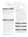
Fig. 3--Mounting
be
maintained
Position
1--Check
L NPA(K
Equipment
and Job
Site
Step
UNIT
Remove carton taking care not to damage
INSPECT
EQUIPMENT
File claim
with shipping
company
or incomplete
prior
Locate
to installation
unit rating
panel
It contains
information
(hock
rating
to be sure unit matches
plate
needed
plate
if shipment
4_Operating
install
a distance
of
or ice from
roof
and the maxin-mm
125°F.
Step
g--Cheek
hstaH
Piston
opeIating
outdoor
Indoor
Ring
2--Bnstall
On
or local codes
down
should
bolts
provided
Level
a Solid,
If conditions
be
require
used
Mounting
and
fastened
1. (hock
Pad
indoor
in unit base pan. Refer to unit mounting
to detem_ine
base pan size and knockout
On rooftop
applications,
unit above
a load-bearing
structure.
Arrange
and nainimize
mount
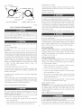
AccuRater®
{38EZG
supporting
members
transmission
coil piston
governing
rooftop
Roof
mounted
units exposed
wind
banes.
(onsult
Pumps
using
NOTE:
Puron®
Unit
compressor
must
to winds
SplitoSystem
be level
manufacturer
above
in Fig
for wind
3
2. After
correct
piston
Place
unit
local
NOTE:
piston
in piston
as shown
stays seated
set ti'om
5 mph may require
and
battle
Service
and Heat
with
÷ 2° (÷ 3/8
piston
outdoor
Install
inJft)
Step
When
installing,
allow
per
The
TXV
Requirements
wiring,
refiigerant
piping,
service
end of unit and 48 in above unit
designed
and service
for
Allow
airflow
30=in
on 1 side of unit and 12 in or* all remaining
clearance
sides
proceed
as
to
a 6oin
must
the required
with
is correct
Teflon
ring
is used
outdoor
fbr any
piston
behind
ring
metering
that piston
conditions.
wit}* a Puron
accessoLw
(38ETG
and 3gESG
reciprocating
hard start kit (capacitor
accessoQ"
and
hard start kit see
be replaced
fbr PuronRL
units
and
38ESG
MLST
Required)
be installed
with
a
TXV.
expansion
with Puron®.
tion Inshqactions
clearance,
For proper airflow,
InstNlation
All 38ETG
thern_ostatic
operate
space
is
Data Digest.
6--TXV
NOTE:
shipped
unit
locate
piston
all operating
an appropriate
the Product
TXV must
3--Clearance
device,
in Fig. 4. The piston ring ensures
If a Puron
compressor,
with
is installed,
bag.
during
hard shut off PuronR:
construction.
specifications.
Step
clearance
coil piston
indoor
shipped
support
Air Conditioners
to within
sufficient
indoor
coil combination.
Consult
Guideline
is 55°F,
mode
and
if it matches
relay) must be used. For the appropriate
Application
Refrigerant
metering
to see
approved
applications.
the
Residential
to building.
fall
unit rating plate. If it does not match,
knockouts
or f?ame.
to adequately
of vibration
mode
in cooling
Piston
with a piston
shipped
hole location.
or* level platfbrm
units.
cannot
Standard)
unit. The piston
pattern
between
in cooling
ambient
to pad, tie
wall and isolate unit and tubing
codes
Manual
replace
through
in
or eaves
unit
job specifications.
the unit be attached
ambient
operating
piston shown on outdoor
Step
24
Ambients
outdoor
If'unit is to be installed
follows:
on unit corner
to properly
snow,
Unit to Pad
on unit
The mininlum
Move to final location
unit,
is damaged
Maintain
so water,
directly
Step
LOCATIONS
B
There
Guideline
Split-System
KNOCKOUT
A
sets,
literature.
Air Conditioners
Residential
TIEDOWN
UNIT BASE PAN
DIMENSIONS
valve
is specifically
De not use an R-22 TXV.
with a factory-approved
To replace
packaged
an Ro22 TXV,
with accessow-
designed
An existing
to
Ro22
TXV specifically
re*_r to Installa-
kit.
NOTE:
FK4 and F(4 tim coils are equipped with an Ro22 TXV.
If an FK4 or an FC4 fire coil is used with a Puron® air conditioner,
the Ro22 TXV must
be replaced
with a Puront_
TXV.
_-COPPERTUBE
HEX BODY
A01164
Fig. 4_AccuRater®
Components
{38EZG Use)
6. Remove bulb flora vapor robe inside cabinet.
Remove
with
indoor
a TXV metering
INPORTANT:
indoor
coil piston if unit is to be installed
The
device.
TXV
coil as possible
mounting
7 Braze equalizer stub-robe closed. Use protective
necessary to prevent damage to drain pan.
on system
should
be mounted
and in a vertical,
the inlet tube vertically
as
upright
down. Valve
close
to the
position.
Avoid
is more susceptible
to malfunction
due to debris if inlet tube is fScing down. A factoQ"
approved filter-&ier
must be installed in the liquid line.
INSTALLING
TXV IN PLACE
1. Pump system
down
OF PISTON
to 2 psig
and recover
2. Remove
coils.
hex nut from piston body.
3. Remove
and discard
piston.
wrench
on fhn
Be sure Teflon
hex nut. Finger
NOTE:
If the piston
function
properly.
tighten
is not removed
:
nut plus
8. Install TXV with 3/8oin. copper tubing through small hole in
service panel. Use wrench and backup wrench, to avoid
damage to tubing or valve, to attach TXV to distributor.
1/2 turn.
flora the bo@,
TXV will not
H
0
To prevent damage to the unit, use a brazing shield
TXV with wet cloth or use heat sink material
10. Attach TXV bulb to vapor robe inside cabinet, in same
location as original was when removed, using supplied bulb
clamps (nylon or copper). See Fig. 5 for con'ect positioning of
sensing bulb.
11 Route equalizer robe through suction connection opening
(large hole) in fitting panel and install fitting panel in place
seal is in place.
4. Reinstall
ff_PORTANT: Route the equalizer tube of Puron¢<; TXV through
suction line connection opening in fitting panel prior to replacing
fitting panel around tubing.
9. Reinstall TXV support clamp (removed in item 3).
refi'igerant.
Use backup
_Sctoryoinstalled
bmTier as
J
and wrap
5. Install TXV on indoor coil liquid line. Sweat swivel adapter to
inlet of indoor coil and attach to TXV outlet Use backup
wrench to avoid damage to tnbing or valve Sweat inlet of
TXV, marked _'IN" to liquid line Avoid excessive heat which
could damage valve.
6. Install vapor elbow with equalize* adapter to suction robe of
line set and suction connection to indoor coil Adapter has a
1/4 in. male connector _br attaching equalize* tube
7. Connect equalizer robe of TXV to 1/4 in. equalizer fitting on
vapor line adapter.
8. Attach TXV bulb to horizontal section of suction line using
clamps provided. Insulate bulb with fieldosupplied insulation
tape. See Fig. 5 tbr con'ect positioning of sensing bulb.
12 Sweat inlet of TXV, marked IN, to liquid
excessive heat which could damage valve.
tine
Avoid
13 Install vapor elbow with equalizer adapter to vapor tine oftine
set and vapor connection to indoor coil. Adapter has a 1/4 in
male connector for attaching equalizer robe.
14 (onnect equalizer robe of TXV to 1/4 in. equalize*" fitting on
vapor line adapter. Use backup wrench to prevent damage to
equalizer fitting.
15. Proceed with remainder of unit installation.
with a TXV metering device
Step
7--Making
Relieve
repair
Use
Piping
pressure
Connections
and recover
or final unit disposal
all service
including
ports
solenoid
and
all refi'igerant
to avoid personal
open
before
system
iriim'y,,-or death.
all flow-control
devices,
valves.
9. Proceed with remainder of unit installation.
REPLACING
TXV ON Ro22 INDOOR (OIL
1. Pump system down to 2 psig and recover refi'igerant.
2. Remove
cabinet.
coil access panel and fitting panel fiom front of
3. Remove TXV support clamp using a 5/16-in. nut driver. Save
the clamp.
4. Remove Ro22 TXV using a backup wrench on flare conneco
tions to prevent damage to tubing.
5. Using wire cutters, cut equalizer robe off flush with vapor robe
inside cabinet.
Do not
leave
system
nainimum
required
extremely
susceptible
ends
of robing
open
to atmosphere
_br installation
sealed
to moisture
during
any longer
POE oil in compressor
absorption
installation.
Always
than
is
keep
_--10
REFRIGERANT
O'CLOCK
"_
2 O'CLOCK 7
TUBING
Connect vapor tube to f_tting on outdoor unit vapor service valves,
Connect liquid tube to filter drier (See Fig 6 and Table 1,) Use
refrigerant grade robing,
SENSING
SWEAT CONNECTION
"L--_SUCTION
TUBE
8 O'CLOCK
4 O'CLOCK
7/8 IN. OD & SMALLER
LARGER
To a\oid
valve damage
while
wrapped
in a heat-sink
material
Service
THAN 7/8 IN. OD
valves
wrapping
A81032
sweat
of Sensing
Bulb
local
and factory
EVACUATE
If ANY refi'igerant tubing is buried, provide a 6 in, x ertical
rise at serxice vah,e Refi'igerant tubing lengths up to 36 in
may be buried v,ithout I:urther special consideration. Do not
bury lines fbr lengths o_er 3d in
damage
to unit
or service
valves
observe
the
a brazing
* Wrap
material
Outdoor
tubing
sen'ice
wet
or use a heat
sink
valves
capacity
For tubing
in
Manual
Residential
Pumps
Ersing Puron(a
Table
1 fbr field
accessory
requirements.
No buried-line
the
cloth
to indoor
losses
Split-System
Refrigerant
robing
using accesso_-
grade robing of correct
requirements
can
Application
applications
section
refiigerant
and performance
recommendations
to
with
or field-supplied
size and condition.
tial
beyond
50 fl, substan-
occur
Following
Guideline
and
Air Conditioners
will reduce
diameters.
greater
these
Refer
the
Service
and Heat
losses.
to Table
Refer
2 for
they
and
in the system.
OETTDOOR I_NIT CONNECTED
INDOOR [NIT
TO FACTORY-APPROVED
Outdoor unit contains cmTect system refrigerant charge %r operation with ARI rated indoor unit with highest sales volume when
connected by 15 t't of field-supplied or fitctow-accesso W robing
Check refi'igerant charge for n_aximum efficiency
INSTALL LIQUID-LINE
FILTER DRIER
W
To axoid
plugged
compressor
circuits
drier in liquid
fi'om fbctory
and ready
drier with
accepted
requirements.
Afier
braze
methods
Refrigerant
t'or leak testing.
%r brazing
a wet cloth,
and materials.
robing
This check
and indoor
should
include
all
joints.
REFRIGERANT
compressor
sor as a vacunnl
TUBING
damage,
AND INDOOR
nexer use the system
COIL
compres=
pump
'
damage
and expansion
II
O
and per%finance
device,
The deep vacuum method requires a vacuum pump capable of
pulling a vacuum of 500 microns and a vacuum gage capable of
accurately measuring this vacuum depth. The deep vacuum
method is the most positive way of assuring a system is flee of air
and liquid water (See Fig. 7,)
Triple Evacuation Method
The triple evacuation method should only be used when vacuum
pump is only capable of pumping down to 28 in of mercu W
vacuum and system does not contain any tiquid water Refkr to
Fig. 8 and proceed as fbllows:
1, Pump system down to 28 in. of" mercu W and allow pump to
continue operating fPr an additional 15 minutes
than 36 in.
If refligerant
robes or indoor coil are exposed to atmosphere,
must be evacuated to 500 microns to eliminate contamination
moisture
must be
Deep Vacuum Method
shield
units may be connected
package
To avoid
xahes
Refiqgerant robes and indoor coil should be evacuated using the
recommended deep vacuum method of 500 microns, The ahernate
triple evacuation method may be used if" the procedure outlined
below is %llowed Always break a vacuum with dW nitlogen,
following:
* Use
code
serxice
such as a wet cloth.
and filter
using industry
coil are now tea@
field
To prevent
valve
connections
Consuh
Fig. 5--PosRion
are closed
service
brazing,
loss
installation
due to
of filter
2, Close service valves and shut off'vacuum pump,
3, Connect a nitrogen cylinder and regulator to system and open
until system pressure is 2 psig
4. (;lose service valve and allow system to stand fbr 1 hr During
this time, &y nitrogen will be able to diffuse throughout the
system absorbing moisture,
5, Repeat this procedure as indicated in Fig 8, System will then
be f?ee of" any contaminants and ware* vapor
FINAL TUBING CHECK
IblPORTANT: Check to be certain factor)' robing on both indoor
and outdoor unit has not shifted during shipment. Ensure tubes are
not rubbing against each other or any sheet metal. Pay close
attention to feeder tubes, making sure wire ties on f_eder tubes are
secure and tight.
Step 8--Make
Emeetrieal Connections
line is required.
Refkr to Fig (5and install filter drier as fbltows:
i*!iuryor
1, Braze 5-in. connector robe to tiquid service valve, Wrap fiher
&ie* with damp cloth
To avoid personal
2, Braze filter drier between connector tube and liquid robe to
indoor coil, Flow arrow must point towards indoor coil
Be sure field wiring
complies
and electrical
and voltage
with compressor
codes,
terminal
death,
do not supply
pox_ er to unit
box cover removed.
with local and national
to system
is within
fire, safkty,
limits
shown
LIQUID-LINE
//////
FILTER-D RYER
CONNECTOR
TUBE
A99331
Fig. 6--Liquid-Line
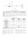
Table 1--Refrigerant
UMT
SiZE
Connections
and Recommended
MOULD
Diameter
Tube Diameter
Connection
Filter Drier
Connection
Liquid Line and Vapor Tube Diameters
VAPOR
Diameter
(in.)
VAPOR {LONG UNE}
Connection Diameter
Tube Diameter
Tube Diameter
0t8, 024
3/8
3/8
5/8
5/8
5/8
030, 036
3/8
3/8
3/4
3/4
3/4
3/4
7/8
042, 048
060
3/8
3/8
3/8
3/8
7/8
7/8
7/8
1-1/8
7/8
7/8
1-1/8
1=1/8
NOTES:
1. Tube diameters are for lengths up to 50 ft. For tubing {engths greater than 50 ft horizontal,
and Service Manual -- Air Conditioners and Heat Pumps Using Puron® Refrigerant
2. Do not apply capillary tube indoor coils to these units.
TaNe 2--Accessory
Crankcase
Heater
Freeze Thermostat
Winter Start Contro_
Accumulator
Compressor
Capacitor
Start Assist
and Relay
MotorMaster®
Control
or
Low-Ambient
Pressure Switch
Wind
Baffle
Coastal
REQUIRED
FOR
LONG-LINE
APPUCATBONS*
(OVER 50 FT)
Yes
Yes
No
No
No
No
No
No
Yes
Yes
No
Yes
No
No
See low-ambient
FHter
instructions
No
No
No
No
Yes
See Long-Line
Application
Guideline
No
Fan Motor
Yes_:
improper
voltage
protection
( ontact local power
See unit rating
plate
_br cot_'ection
fbr recommended
of
circuit
device.
NOTE:
Operation
install unit in system
pem_issible
Use
of unit
on improper
where
voltage
line voltage
constitutes
See unit rating plate.
Install
NEC to handle
may fluctuate
above
wire
only
between
disconnect
branch
No
and Heat Pumps Using Puron® Refrigerant
circnit
unit starting
accessible
disconnect
current
Locate
of
adequate
disconnect
from unit, per Section
size
within
440-14
per
sight
of NEC.
ROUTE GROUND AND POWER WIRES
Do not
or below
limits.
copper
NOTE:
from and readily
abuse and could affect unit reliability.
NOTE:
unit
company
No
No
* For tubing line sets between 50 and 175 ft, refer to Application Guideline and Service Manual -- Air Conditioners
1 Only when low-pressure switch is used
$ Required for low-ambient controller (full modulation feature) and MotorMaster® Control only.
on unit rating plate
Guideline
REQUIRED
FOR
SEA COAST
APPUCATIONS
{WITHIN 2 MRLES)
No
Yest
No
Liquid_LineSolenoid Valve
or
Hard Shutoff TXV
BaH Bearing
consult the Application
Usage
REQUIRED
FOR
LOW-AMBII=NT
APPLICATIONS
{BELOW 55°F)
Yes
ACCESSORY
Evaporator
or greater than 20 fl vertical differential,
switch
and
Remove
access
from disconnect
cont*ol box
panel to gain access
through
power wiring
to unit wiring.
hole provided
Extend
wires
and into unit
DISCONNECT
PER N.E.C. AND/OR
LOCAL CODES
50O0
4500
1
4000
3500
CONTACTOR
<?o
z 3000
_2500
FIELD POWER
_2000
WIRING
VACUUM TIGHT
TOO WET
1500
3 PHASE ONLY
BLUE
1000
500
FIELD GROUND
WIRING
0
1
2
3
4
MINUTES
5
6
C
3
TIGHT
DRY SYSTEM
@
GROUND
LUG
l
7
A94025
A95424
Fig. 7--Deep
Fig. 9--Line
Vacuum Graph
NOTE:
I EVACUATE
I
Use
mum 40va
of available
power
ing and increase
IBREAK
VACUUM
WiTH
DRY
NITROGEN
accessory
I
IBREAK
VACUUM
W,TH
DRY
NITROGEN
I
F- vq
the transfbmaer
capacity'
t_ansformer
Step
9--Compressor
When
equipped
minimum
may exceed
the mini-
total transformer
load-
or split the load with an
as required.
Crankcase
with a crankcase
of 24 hr before
only, set fl-iermostat
outdoor unit.
IEVAOUATEI
A crankcase
(IF IT HOLDS
Determine
IMPORTANT: Check factory wiring and field wire connections
to ensure terminations are secured properly Check wire routing to
ensure wires are not in contact with tubing, sheet metal, etc
IEVAOUATEI
FOR TIGHT,
24v accessories
requirement.
FINAL WIRING CHECK
F- vq
CHECK
Power Connections
DRY SYSTEM
50
DEEP VACUUM)
ft
heater
Refer
Residential
To fl/mish
and close
is required
1o Application
Split-System
fl/rnish
unit
starting
to OFF
Heater
heater,
power
electrical
if re['rigerant
Guideline
robing
a
1o heater
disconnect
to
is longer
and Service
Air Conditioners
to heater
power
than
Manual
and Heat Pumps
using
Puron R; Refrigerant
[CHARGE
SYSTEM
I
A95425
Fig. 8--Triple
Evacuation
Step
Method
Step
The
unit
ground
cabinet
must
to minimize
should
occur
metal
condnit
electrical
The
have
ground
when
shock,
injury
if an
may consist
installed
codes. Failure
electric
an maintem/pted
personal
fault
in accordance
wire
with
or
To prevent
existing
Connect
ground
safety.
Connect
AND
wire
can result in an
*Do not overcharge
*Do not operate
CONNECT
CONTROL
Route
control
24v
connect
thermostat
All
excessive
wiring
incoming
must
power
for control
connection
through
wiring.
color-coded,
more
voltage
not
system
in control
as shown
box
or personal
injury,
observe
for
in Fig. 9.
vent
repair
system
with refiigerant.
unit in a vacuum
refiigerant
to
or at negative
atmosphere.
pressure.
Recover
during
or final unit disposal.
*Do riot disable
low=pressure
switch.
In scroll=compressor
applications:
*Dome
may be hot.
temperatures
be NEE
contlol
wiring
grommet
and
(See Fig. 11.)
insulated
than
wires,
voltage
(35°C
100 ft t'rom
minimnm)
unit,
wire. If
as measured
use No. 16 AWG color-coded
wire
Class
power,
1 and mnst
f_n coil transformer,
24vi40va
To prevent
clothing,
personal
be separated
fi'om
minimun_.
or accesso_
trans-
injury
and gloves
when
wear
handling
safety
glasses,
refi'igerant
protective
arid observe
the fbllowing:
*Back=seating
drop.
leads.
Use l?urnace tlansformer,
fbrmer
WIRES
to contactor
damage
WIRING
wires
is located
along the contlol
to avoid
wiring
leads to conhoi
Use No. 18 AWG
POWER
to ground
po_er
compressor
the fbllowing:
fire, or death
GROL_D
Accessories
1 l--Start-Up
*Do
(ONNE(T
Electrical
or unbroken
electrical
of electrical
to follow this warning
10--install
Refer to the indixidual instructions packaged x_ith kits or accessories when installing.
valves.
removing
service
valves
are riot equipped
Fully back seat (counterclockwise)
gage=port
*Front-seating
valves,
with Schrader
valve stem before
cap.
service
valves
are
equipped
with
Schrader
m
° 3-phase
scroll
° A flashing
compressors
are rotation
LED on phase
(See Fig. 10 and Table
° This will
not allow
monitor
contactor
these
steps
to properly
system
is evacuated,
vapor
service
valves.
is shipped
fully back
replace
electrical
4_ Set room
stem
is below
indoor
5_ Set room
mode,
disconnects
thermostat
seat (open)
fi'ont seated
caps
aiier
ambient
refi'igerant
and
and
is opened
and tighten
to
with
Step
12--Check
UNIT
(HARGE
Factory
Charge
charge
and charging
Be sure set point
in manifold
NOTE:
charge
÷ 0.6
to ON or AUTO
unit for 15 minutes
Check
system
OF OPERATION
power
oziff
of 3/8-in.
three phase models
and
thermostat
outdoor
units
to detect
ibr compressor
blower
NOTE:
25 ft - 15 ft
COOLING
Transfom_er
is
phasing
To correct
line
charge
required
line.
conditions
above
are not
with unit rating
or below
15 ft
for a 25-fl line set:
6 oz of additional
charge
PROCEDURE
installed
is correct,
relay,
circuit
the phasing,
the contactor
interchange
When
ff_ermostat
is satisfied,
its
and blower
unit
relay.
an
with cooling
unit
TXV
mode
a minimum
liquid service
gage to service
3. Measure
TXV
require
with
open,
and motors
a time-delay
additional
90
sec
will
not
be
liquid
of
10 minutes
relay
circuit,
the
system
efficiency.
CONTAC
IDR
@
O
be_bre
checking
valve pressure
by attaching
an accurate
line
or
temperature
electronic
by
attaching
thermometer
an
to
accurate
liquid
subcooling
near
temperature.
required
subcooling
temperatuie
at a specific
liquid
line pressure,
add refi'igerant
if liquid line temperature
higher than indicated or reclaim refrigerant
if temperature
lower. Allow a tolerance of ÷ 3°F.
stop.
to increase
by the
5. Refkr to Table 4. Find the point where required
subcooting
temperature
intersects measured liquid service valve pressure.
6. To obtain
de-energizing
charging
port.
thennistor
type
outdoor coil.
indoor
any two of the three
contacts
Compressor
is equipped
runs
Puron®
method.
2. Measure
and compresstarting
Mode
4. Refkr to unit rating plate fbr required
is incon'ect,
side.
blower
charging
metering
suction
charge.
is correctly
on high speed.
on the field
indoor
power
finn motor
indoor unit blower
connections
If indoor
the units are equipped
outdoor
power
contactor
into
in accordance
liquid
10 ff X 0.6 oziff
ONLY
subcooling
R-Y and R-G. On
If the phasing
starting
R-G energizes
If the
energized.
circuits
in the incoming
operation.
contactor,
motor
makes
with scroll compressors,
monitor
R-Y energizes
sor circuit.
on unit informa-
a commercial-type
refi'igerant
or subcooling
additional
1. Operate
On a call for cooling,
phased
are shown
EXAMPLE:
Units
to indoor
energize&
with a phase
Charge
must be weighed
Units with Cooling
on
method
units using
hose.
If superheat
favorable,
To calculate
and fan control
Puron®
charge.
SEQUEN(E
Turn
operation
Reversed phase
Normal
respectively.
temperature.
Operate
device
plate
system.
temperature.
to (OOL
as desire&
liquid
(closed)
system
to energize
at desired
thermostat
No calt for compressor
2 field wiring
refiJgerant
flow. Replace caps finger-tight
wrench an additional
1/12 ram.
3_ (;lose
OFF
tion plate_ Charge
stem(s)
Led Indicators
STATUS
FLASHING
ON
to be energize&
with valve
caps installed,
rotation
start up the system.
1_ Alier
2_ /nit
reverse
and interchange
Monitor
LED
sensitive.
indicates
3.)
° Disconnect
power to unit
leads on unit contacton
Follow
TaNe 3--Phase
Units with Indoor
Pistons
Units installed
heat metho&
with
The fbllowing
procednre
21 percent
1
indoor
of its rated
Operate
is
is
unit
pistons
require
is valid when
charging
indoor
by the super-
airflow
is within
÷
(FM.
a minimum
of
10 minutes
befbre
checking
charge_
2. Measure
suction
suction
valve
3. Measure
mistor
valve.
OFFsNO
ON sol<
FLASHsPHASE
24VAC
PROSLEH
suction
outdoor
5. Measure
indoor
gage to
temperature
by attaching
thermometer
air &y-bulb
air (entering
temperature
indoor
an accurate
to suction
ther-
line at service
with thennometer.
coil) wet-bulb
tempera-
Refkr
to Table
5. Find
air wet-bulb
outdoor
temperature
temperature
and evaporator
At this intersectiom
note
superheat.
LI
AO0010
Monitor
an accurate
ture with a sling psychrometer.
L2
entering
Fig, lO--Phase
by attaching
port.
type or electronic
4. Measure
6
L3
pressure
service
Control
7. Refkr to Table
and suction
temperature
6. Find superheat
pressure.
temperature
At this intersection,
located
in item 6
note suction
line
Table 4_Requi/ed
REQUIRED
SUBCOOLING
TEMPERATURE
LIQUIO
PRESSURE
AT
SERVICE
VALVE
2. Tighten
(OF)
service
8
10
12
14
16
18
189
58
56
54
52
50
48
195
60
58
56
54
52
50
202
62
60
58
56
54
52
208
64
62
60
58
56
54
215
66
64
62
60
58
56
222
68
66
64
62
60
58
229
70
68
66
64
62
60
236
72
70
68
66
64
62
For continuing
243
74
72
70
68
66
64
251
76
74
72
70
68
66
ment failure,
equipment
259
78
76
74
72
70
68
266
80
78
76
74
72
70
274
82
80
78
76
74
72
283
84
82
80
78
76
74
291
86
84
82
80
78
76
299
88
86
84
82
80
78
308
90
88
86
84
82
80
317
92
90
88
86
84
82
826
94
92
90
88
86
84
335
96
94
92
90
88
86
345
98
96
94
92
90
88
354
100
98
96
94
92
90
364
102
100
98
96
94
92
374
104
102
100
98
96
94
384
106
104
102
100
98
96
895
108
106
104
102
100
98
406
110
108
106
104
102
100
416
112
110
108
106
104
102
427
114
112
110
108
106
104
439
116
114
112
110
108
106
450
118
116
114
112
110
108
462
120
118
116
114
112
110
474
122
120
118
116
114
112
486
124
122
120
118
116
114
499
126
124
122
120
118
116
511
128
126
124
122
120
118
8, If a unit has a higher
temperature,
reache&
9. If unit
add
has
temperature,
reached.
10. When
adding
service
changes,
chart.
suction
ref?igerant
ref?igerant,
air
line temperatuie
until
reclaim
charge
13--Final
mMPORTANT:
suction
rekigerant
a lower
port using
11. If outdoor
Step
1, Ensure that all wiring and robing is secure in unit be%re
adding panels and coxers Securely fasten all panels and
covers,
Liquid-Line Temperature (°F)
line
charge
temperatore
or
charted
in liquid
than
%rm
leaving
areas, such
mation
charted
is
into suction
pressure
at
suction
valve
indicated
Checks
Before
Frequency
job, be sure to do the following:
on
with owner
AND
Cl]ecklist
maintenance
of maintenance
as coastal
past finger
system
outlined
and place
tight.
operation
in manual.
in customer
MAINTENANCE
high per%m_ance
periodic
Explain
requirements
InMallation
CARE
device.
line temperature
Manual
maintenance
4. Fill out Dealer
file,
is
temperature
User's
and periodic
than charted
temperature
temperature
until
a flow=restricting
to new suction
charted
3. Leave
valve stem caps to 1i12-mm
and to minimize
must
may vary depending
applications.
possible
be perfbm_ed
See User's
upon
Manual
equip=
on this
geographic
for infor-
Table 5--Superheat
OUTDOOR
TEMP
[°F}
55
EVAPORATOR
ENTERING
Charging
ABR TEMPERATURE
(°FWB)
50
9
52
12
54
14
56
17
58
20
60
23
62
26
64
2g
66
32
68
35
70
37
72
40
74
42
76
45
60
7
10
12
15
18
21
24
27
30
33
35
38
40
43
65
--
6
10
13
16
19
21
24
27
30
33
36
38
41
70
--
--
7
10
13
16
19
21
24
27
30
33
36
39
75
--
--
--
6
9
12
15
18
21
24
28
31
34
37
80
....
5
8
12
15
18
21
25
28
31
35
88
......
8
11
15
19
22
26
30
33
90
......
5
9
13
16
20
24
27
31
95
.......
6
10
14
18
22
25
29
100
........
8
12
15
20
23
27
105
........
5
9
13
17
22
26
110
.........
6
11
15
20
25
8
14
18
23
..........
118
Table 6--Required
SUPERHEAT
TEMP
{OF}
0
Suction-Line
SUCTION
PRESSURE
Temperature (°F WB)
AT SERVICE
PORT (PSIG}
107.8
35
112.2
37
116.8
39
121.2
41
126.0
43
130.8
45
138.8
47
140.8
49
145.8
5I
2
37
39
41
43
45
47
4g
51
53
4
39
41
43
45
47
49
51
53
55
¢
41
43
45
47
4g
51
53
55
57
8
43
45
47
49
51
53
55
57
59
10
45
47
49
51
53
55
57
59
61
t2
47
49
51
53
55
57
5g
61
63
14
49
51
53
55
57
59
61
63
65
t6
51
53
55
57
5g
61
63
65
67
18
53
55
57
59
61
63
65
67
69
20
55
57
59
61
63
65
67
69
71
22
57
59
61
63
65
67
69
71
73
24
59
61
63
65
67
69
71
73
75
26
61
63
65
67
6g
71
73
75
77
28
63
65
67
69
71
73
75
77
79
30
65
67
69
71
73
75
77
79
81
32
67
69
71
73
75
77
7g
81
83
34
69
71
73
75
77
79
81
83
85
36
71
73
75
77
79
8I
83
85
87
38
73
75
77
79
81
83
85
87
89
40
75
77
79
81
83
85
87
89
91
A/C
THERMOSTAT
Typical
FURNACE
A/C
THERMOSTAT
A}R
CONDmONER
Typical
FAN CO_L
AIR
CONDITIONER
24 VAC HOT
24 VAC HOT
24 VAC COM
24 VAC COM
HEAT STAGE 1
F_
HEAT STAGE 1
COOL STAGE 1
F_
COOL STAGE 1
INDOOR FAN
(See Thermostat
D'
INDOOR FAN
Fig. 11--Generic Wiring Diagram
Installation
instructions for wiring specific
A02326
unit combinations)
LEGEND
24-V FACTORY WIRING
24-V FIELD WIRING
FIELD SPLICE CONNECTION
CONTACTOR
A97368
10
II
PURON@ (R-4t0A)
QUICK REFERENCE
GULDE
• Puron® refrigerant operates at 50-70 percent higher pressures than R-22. Be sure that servicing equipment
replacement components are designed to operate with Puron®.
• Puron® refrigerant
and
cylinders are rose colored.
• Recovery cylinder service pressure rating must be 400 psig. DOT 4BA400 or DOT BW400.
• Puron® systems should be charged with liquid refrigerant. Use a commercial
manifold hose when charging into suction line with compressor operating.
type metering device in the
• Manifold sets should be at least 700 psig high side and 180 psig low side with 550 psig low-side retard.
• Use hoses with 700 psig service pressure rating.
• Leak detectors should be designed to detect HFC refrigerant.
• Puron®, as with other HFCs, is onty compatible
with POE oils.
• Vacuum pumps will not remove moisture from oil.
• Do not teave Puron® suction line filter driers in line longer than 72 hrs.
• Do not use liquid-line filter driers with rated working pressures less than 600 psig.
• Do not install a suction-line
• POE oiis absorb moisture
filter drier in tiquid line.
rapidty. Do not expose oil to atmosphere.
• Poe oils may cause damage to certain plastics and roofing materials.
• Wrap all filter driers and service valves with wet cloth when brazing.
• A factory-approved liquid-line filter drier is required on every unit.
• Do not use an R-22 TXV.
• If indoor unit is equipped with an R-22 TXV, it must be changed to a Puron® TXV.
• Never open system to atmosphere
while it is under a vacuum.
• When system must be opened for service, recover refrigerant, break vacuum with dry nitrogen prior to
opening to atmosphere. Evacuate to 500 microns prior to recharging.
• Atways replace filter drier after opening system for service.
• Do not vent Puron® into the atmosphere.
• Do not use capillary tube coils.
• Observe alt warnings,
cautions,
and bold text.
Copyright 2002 CARRIER Corp. _ 7310 W. Morris St • Mdianapolis, IN 46231
Manufacturer
Book 1 4
Tab 3a 2a
reserves
PC 101
the
right
Catalog
to discontinue,
or
No 533-80079
change
at any
time,
38esglsi
specifications
PrJl3tedin U.S.A.
or designs
Form 38ESG-1SI
without
notice
and
Pg 12
without
incurring
1%02
obJigations.
Replaces: New