1
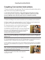
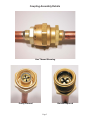
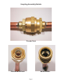
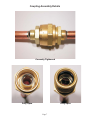
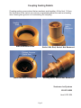
Refrigeration Line Set Installation
Details of Quick Connect Coupling Assembly
Quick connect coupling assembly can be as simple as tightening a nut. But if
not done properly, an expensive, not-covered-by-warranty refrigerant leak
will occur. This booklet lists correct assembly steps, shows results of partial
assembly and describes how a leak proof joint is made.
Male Fitting Before Connecting
Male Fitting After Connecting
Coupling Assembly Details
Coupling Connection Instructions
1. Remove the protector caps and plugs. Wipe the seats and threaded surfaces with a
clean cloth to remove any possible foreign matter.
2. Thoroughly lubricate the threads, o-rings, diaphragms and all internal coupling
surfaces with polyolester refrigerant oil. Failure to lubricate could cause a false
sense of tightness and a leak will result from the incomplete assembly.
Note: Scotsman line sets include lubricant packets.
3. Position the fittings on the correct connections on the condenser and ice machine.
4a. Begin to tighten the couplings together by hand. Continue to turn the swivel nuts
by hand until it is certain that the threads are properly engaged.
4b. Using two wrenches, one to rotate the swivel nut and
one to hold the tubing in place, tighten each coupling.
It is CRITICAL that ONLY the NUT on the pre-charged tube
be turned, or the diaphragms will be torn by the piercing
knives and become loose in the refrigeration system
causing severe operational problems.
Note: As the coupling is tightened, the diaphragms in the quick connect couplings will
begin to be pierced. As that happens, there will be increased resistance to tightening
the swivel nut.
4c. Continue tightening the swivel nut until it bottoms out or a very definite increase in
resistance is felt (no threads should be showing). Do NOT overtighten.
5. Use a marker or pen to mark a line on the coupling nut and unit panel. Then tighten
the coupling nut an additional one-quarter turn. The line will show the amount that the
nut turns.
Note: The final 1/4 turn forces two shoulders on the swivel
nut end into the beveled surface of the male end, resulting
in a sealed brass-to-brass connection.
6. After all connections have been made check the
couplings for leaks.
Page 2
Coupling Assembly Details
Coupling Description
The following pages show the stages of coupling assembly as
the swivel nut and male fitting are drawn together.
The swivel nut end contains one diaphragm in the center post. The male fitting
contains the knife blades and its own diaphragm.
Note: 3/8 male ends have one knife blade.
No sealing takes place until the final stage, when the outer edge of the center post in
the swivel nut is forced against the bottom of the male fitting, creating a mechanical
seal.
• Page 4 shows what appears to be a completed assembly with only two threads
showing, but the diaphragms have just begun to be pierced. Stopping here
causes severe operational issues as well as refrigerant leaks.
• Page 5 shows an even more complete assembly, with only one thread showing.
However, this assembly is still not complete. If not tightened further there will be
refrigeration restrictions and leaks.
• Page 6 shows the two parts almost together; the threads are flush. At this point
the main problem will be refrigerant leaks.
• Page 7 shows the couplings properly assembled with the critical last 1/4 turn.
• Page 8 shows details of the brass-to-brass sealing action, not visible when the
couplings are assembled.
Note that couplings that are screwed together but have threads
showing are not only leaking refrigerant, they are restricting the
flow of refrigerant through the small slits in the membranes or
diaphragms.
Page 3
Coupling Assembly Details
Two Threads Showing
Barely Pierced
Knives Just Showing
Page 4
Coupling Assembly Details
One Thread Showing
Partly Pierced
Knives Exposed
Page 5
Coupling Assembly Details
Threads Flush
Pierced but will leak
Knives Visible
Page 6
Coupling Assembly Details
Correctly Tightened
Fully Open
Fully Open
Page 7
Coupling Sealing Details
Coupling sealing occurs when the two sections seat together. At the final 1/4 turn,
the shoulders in the swivel nut end are compressed against the male end sealing
area, forming two grooves in it and sealing the coupling.
Sealing
Area
Sealing
Area
Shoulders
Male End Before Use
Swivel Nut End, Swivel Nut Removed
Formed Grooves
Create Seal
Seat
Male End After Connection
Seating Area, Swivel Nut Removed
Scotsman Ice Systems
800-533-6006
item # 291-824
Page 8