1
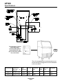
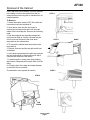
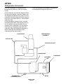
AF300
INTRODUCTION
To the owner or user: This service manual is
intended to provide you, and the maintenance or
service technician, with the information needed to
install, start up, clean, maintain and repair this
product.
This unit in serviceable in place; the ice storage
bin and hood may be removed from the chassis to
allow service access without removing the ice
machine from its installed location. The
refrigeration system uses R-22 as the refrigerant.
The AF300 is an ice machine that produces flaked
ice and stores it in a insulated bin. It automatically
maintains the level of ice by turning on when the
ice level falls and switches off when it is full.
Table of Contents
Specifications
. . . . . . . . . . . . . . . . . . . . . . . . . . . . . . . . . . . . . . page 2
Limitations
. . . . . . . . . . . . . . . . . . . . . . . . . . . . . . . . . . . . . . . page 3
Installation
. . . . . . . . . . . . . . . . . . . . . . . . . . . . . . . . . . . . . . . page 4
Plumbing . . . . . . . . . . . . . . . . . . . . . . . . . . . . . . . . . . . . . . . . . page 5
Final Check List . . . . . . . . . . . . . . . . . . . . . . . . . . . . . . . . . . . . . page 6
Cabinet Removal
Component Location
. . . . . . . . . . . . . . . . . . . . . . . . . . . . . . . . . . . page 7
. . . . . . . . . . . . . . . . . . . . . . . . . . . . . . . . . . page 8
Electrical Sequence . . . . . . . . . . . . . . . . . . . . . . . . . . . . . . . . . . . page 9
Initial Start Up . . . . . . . . . . . . . . . . . . . . . . . . . . . . . . . . . . . . . . page 10
Cleaning . . . . . . . . . . . . . . . . . . . . . . . . . . . . . . . . . . . . . . . . . page 11
Water Schematic
. . . . . . . . . . . . . . . . . . . . . . . . . . . . . . . . . . . page 15
Refrigeration Schematic . . . . . . . . . . . . . . . . . . . . . . . . . . . . . . . . . page 16
Technical Charateristics . . . . . . . . . . . . . . . . . . . . . . . . . . . . . . . . . page 17
Service Diagnosis
. . . . . . . . . . . . . . . . . . . . . . . . . . . . . . . . . . . page 18
Removal and Replacement . . . . . . . . . . . . . . . . . . . . . . . . . . . . . . . page 20
Parts lists and wiring diagrams are located in
the center of this manual, printed on yellow
paper.
Keep this manual for reference.
This manual was printed on recycled paper.
AF300
Specifications
14.25 IN
The nameplate is located
on the back panel.
A serial number plate is
located behind the right
grill, in front of the control
box, on the base.
SERIAL
NUMBER
PLATE
The unit is equipped with an electrical power cord,
but should only be plugged into a circuit dedicated
to the ice machine.
Basic
Electrical
Ice Type
Condenser
Type
Typical
Amps
Maximum
Fuse
Refrigerant
115/60/1
Flake
Air
9
15
R-22
AF300WE-1A 33 x 241⁄4 x 24 115/60/1
A scoop and legs (6") are included.
Flake
Water
9
15
R-22
Model Number Dimensions
(w/o) legs
H
xWxD
AF300AE-1A 33 x 241⁄4 x 24
January 1993
Page 2
AF300
For The Installer: Environmental Limitations
The ice machine must be installed indoors in a
controlled environment.
Minimum
Maximum
Air Temp
0
50 F.
1000F.
Water Temp
400F.
1000F.
Water Pressure
20 PSI
80 PSI
Voltage
103.5
126.5
AIR OUT
Operating the ice machine outside of the above
limitations, or outdoors, is potentially damaging to
the machine, and it is misuse of the machine. This
may void the warranty.
Scotsman Ice Systems are designed and
manufactured with the highest regard for safety
and performance. They meet or exceed the
standards of UL, NSF, and CSA.
Scotsman assumes no liability or responsibility of
any kind for products manufactured by Scotsman
that have been altered in any way, including the
use of any part and/or other components not
specifically approved by Scotsman.
AIR IN
Airflow on air cooled models:
• Intake through the right grill.
• Exhaust from the left grill.
Do not install wher this air flow is blocked.
The AF300 has a removable cabinet. When
installed, the machine should have some extra
clearance (1/8") on the left and right sides so that
the cabinet may be easily removed when the
machine is in place.
Scotsman reserves the right to make design
changes and/or improvements at any time.
Specifications and design are subject to change
without notice.
January 1993
Page 3
AF300
Installation:
Water
The water supply for this ice machine has been in
contact with many materials since it fell from the
sky as rain. All rain is slightly acidic, and tends to
dissolve the materials it comes in contact with.
During water’s journey to the ice machine, it has
flowed over and through the ground, been picked
up by a municipal or private pump, forced through
a series of pipes of differing construction and may
have been treated by the municipality providing
the water.
The water supplied to this ice machine will then
contain a variety of substances that will likely show
up as solids during the ice making process. These
solids are similar to those found when water is
boiled out of a saucepan. Only the water boils
away, and the minerals that were in the water
solidify in the pan. During ice making the water is
frozen into ice, and many of the minerals stay
behind in the ice machine water system. After time
the minerals will have to be dissolved by ice
machine cleaner, then flushed away during the
cleaning process.
An ice machine is a food manufacturing plant; it
takes a raw material, in this case water, and
transforms it into a food product, ice. The purity of
the water is very important in obtaining pure ice
and in maximizing product life.
The water to the ice machine should be filtered.
Water filters vary greatly in ability and function.
Install one that filters out suspended solids to a
dimension of 5 microns or less. The finer the filter
the better, but finer filters may plug-up sooner than
course ones. It may be necessary to add a course
filter ahead of the fine filter to prolong filter life.
This ice machine may be installed in the open or
under a counter. No clearance is required at the
sides or top beyond what’s needed to place the
cabinet into position. Air cooled models blow air in
and out through the grills at the front. Space is
required for utility connections at the back.
The ice machine is not designed for outdoor
use. It must be installed indoors, in a
controlled environment. The air and water
temperatures must not exceed rated limits.
Electrical power is supplied through a cord
connected to the unit. All local codes must be
followed.
Pre-installation:
1. Inspect the place where the ice machine is to be
installed. Check for:
• space for the cabinet
• water supply,
• drain availability
• and electrical power supply.
No extension cords are allowed. The building drain
inlet must be lower than the drain outlet(s) at the
back of the ice machine. The water supply must
have a hand shut off valve accessible when the
unit is installed.
2. Determine the method of installation, is the
machine to be installed under the counter? Is the
drain in the floor under the machine? Is the water
inlet accessible from the top?
Have the water tested. Either acidic water or
alkaline water will cause corrosion. Dissolved
solids cannot be filtered out. Check with a water
treatment specialist regarding testing, treatment
and filters.
January 1993
Page 4
AF300
Installation:
For The Plumber
1. Connect cold potable water to the 3/8" male
flare at the top back of the cabinet. A water filter is
recommended. Flush the water line prior to
connecting to the ice machine.
A loop of copper tubing may be used between the
ice machine and the water supply. This will allow
the ice machine to be pulled out from its installed
location without disconnecting the water line. No
back-flow preventer is required in the inlet potable
water line because provision for that is
incorporated in this N.S.F. listed product (the float
seat is above the reservoir water level and cannot
siphon).
2. Connect a drain tube the drain fitting. If water
cooled, the drain tubes must be run separately.
The bin drain fitting is 3/4" F.P.T. brass.
• Drain tube material must be rigid and meet local
code.
• Traps in the bin drain line without vents ahead
of them will cause poor draining.
• The bin drain must be vented if there is a long
horizontal run (5’ or more). All drains are
gravity, and must have a minimum fall of 1/4"
per foot of horizontal run.
• Maintain the air gap required by local code
between the end of the drain tubes and the
building drain receptacle.
• Drain tubing should be insulated to prevent
condensation from forming on the tubing.
3.The unit is set up for drain connections on the
outside of the cabinet. To connect the drains inside
would require the removal of the drain fittings
attached to the back panel, and field fabricated
drain tubes routed inside the base of the unit.
AIR COOLED
PLUMBING
POTABLE
WATER
INLET
BIN DRAIN
WATER COOLED
PLUMBING
FLOOR
DRAIN
RESERVOIR
OVERFLOW
DRAIN
DETAIL OF DRAIN,
VENT IF OVER 5’ OF
HORIZONTAL RUN
POTABLE
WATER INLET
CONDENSER
DRAIN
CONDENSER
INLET
January 1993
Page 5
AF300
Installation
For The Electrician
This is a cord-connected unit, and must be on a
separate 115 volt AC 60 cycle single phase power
supply. The maximum fuse size for this circuit
should be 15 amps, per the nameplate use fuses,
or HACR circuit breakers.
Follow All Local Codes - THIS UNIT MUST BE
GROUNDED. Do not use extension cords and do
not disable or by-pass ground plug on electrical
plug.
After Utility Connections:
1. Level the cabinet, use the leg levelers on the
end of the legs to adjust the cabinet height. (Legs
should have been installed when the unit was
unpacked).
2. Wash the bin and hood. If desired, the interior of
the bin could be sanitized.
3. Locate the scoop, wash it and have it available
for use when needed.
Final Check List
1. Is the ice maker cabinet in a room where
ambient temperatures are within the minimum and
maximum temperatures specified?
12. Has the owner/user been given the name and
telephone number of the authorized Scotsman
Service Agency serving that location?
2. Has the water supply been connected?
3. Is the water pressure adequate?
4. Have the water connections been checked for
water leaks?
5. Have the drain connections been made?
6. Have the drain connections been checked for
leaks?
7. Is the cabinet level?
8. Is the ice machine plugged into a 115 volt
electrical power supply and is the ice machine the
only load on that circuit?
9. Has all of the shipping material been removed
from the inside of the cabinet?
10. Has the bin and cabinet been wiped clean and
sanitized?
11. Has the Customer Evaluation & Warranty
Registration form been filled out? Check for correct
model and serial numbers from the nameplate,
then mail the completed form to Scotsman.
January 1993
Page 6
AF300
Removal of the Cabinet
One of the most useful features of this ice machine
is the ability to remove the cabinet from the ice
machine without removing the ice machine from its
installed position.
STEP 2
To Remove:
1. Switch the master switch to OFF. Be certain the
ice machine has been switched off.
2. Open the bin door and turn the knobs to
unscrew the mounting bolts at the left and right
inside of the ice storage bin. Remove the mounting
bolts.
3. Pull the hood and door assembly straight out
until it can be lifted up. Caution: the door may be
free to come out the back of the hood when
removed from the cabinet base.
STEP 3
4. To remove the cabinet base the hood must be
removed first.
5. Remove 4 screws and the two grills at the front
of the base.
6. In the area exposed when the grills are removed
are two knobs similar to those removed in step 2.
Unscrew and remove the two knobs.
7. Locate bin drain. Loosen hose clamp holding
drain tube to fitting and pull the drain tube off of the
fitting.
8. Lift up the front of the base and rotate the base
up and off of the ice machine.
The machine is now exposed for service.
STEP 5
STEP 8
STEP 6
BIN
DRAIN
January 1993
Page 7
HOOD
AF300
Component Location
The ice machine is designed for front service.
Many components are serviceable from the front
without removing the cabinet. With the cabinet
removed, nearly all components are serviceable.
In the bin area can be found
• Float
• Reservoir
• Evaporator
• Bin Thermostat sensing tube
Behind the right front grill on the front edge of the
control box:
• Bin thermostat
• Master switch
Inside the control box are the auger delay control,
low pressure cut out, and the contactor.
Auger Delay Pressure Control: This pressure
switch, connected to the low side of the
refrigeration system, controls the auger drive
motor.
Low Pressure Control: This pressure switch,
connected to the low side of the refrigeration
system, is normally closed when the machine is
operating. If the low side pressure should drop too
low, the control will open (at 0-4 PSIG), stopping
the ice maker. It is an automatic reset.
High Pressure Control: The pressure switch is
designed to open and shut off the machine should
the high side refrigeration pressure become too
high, usually as a result of not enough water
through the water cooled condenser.
It is a manual reset.
On-Off switch: This toggle switch shuts off the
machine. It is not a complete disconnect.
Bin Thermostat: This thermostat turns the
machine on and off in response to changes in
temperature of the capillary tube. At the minimum
setting, it opens at 350 F. and closes at 450 F. At
the maximum setting, it opens at 51oF. and closes
at 61oF. See "Initial Start Up" for adjustment
information.
COVER PLATE
CUTAWAY VIEW
BIN THERMOSTAT
BRACKET
RESERVOIR
STRAINER
CONTROL BOX
HI PRESSURE CUT OUT
January 1993
Page 8
AF300
Electrical Sequence
There are two circuits in the AF300: one is a series
circuit with several switches connected in series to
the compressor. The other is a parallel branch of
the series circuit, controlling the gear drive motor.
• The series circuit begins at the contactor in the
control box. From there, the line side power is
connected to the Master Switch.
• From the master switch the line side power is
connected to the Low Pressure Control and
then the High Pressure Control. These controls,
connected to the refrigeration system, are
designed to open whenever higher (high
pressure control) pressures or lower (low
pressure control) pressures are sensed. The
high pressure control is a manual reset, the low
pressure control is an automatic reset.
• The line side power is also connected, in a
parallel circuit, to terminal 1 of the Auger Delay
pressure control. This pressure control,
connected to the low side of the refrigeration
system, is designed as a by-pass circuit to the
auger drive motor whenever the low side
refrigerant pressure is at it’s normal ice making
range. At start up, the contacts between
terminals 1 and 2 are open. The line side power
does not pass any further through the auger
delay pressure control, until the compressor
starts, and the low side pressure drops.
• The next control the power is connected to is
the Low Water Pressure Control. This switch is
designed to open should the water pressure to
the machine drop too low.
• The next control is the Bin Thermostat. It is
closed when there is no ice on the portion of the
control inside the thermostat bracket It is open
when there is ice on the portion of the control
inside the thermostat bracket. Closing of the bin
thermostat begins the process of making ice,
because the line side power now goes to the
compressor contactor coil.
• Power is initially connected to the gearmotor
through contacts 3 and 2 of the auger delay
pressure control. This causes the auger motor
to start and run. At the same time, if the
centrifugal switch on top of the gearmotor
closes (meaning the motor is at full speed) the
compressor contactor coil is connected to the
neutral side of the power supply, and the
compressor begins to run.
• As the compressor operates, the low side or
suction pressure begins to fall, when it reaches
a preset point, the contacts within it move,
opening 3 and 2, then closing 1 and 2. The
power for the gearmotor is then connected to a
point in the series circuit ahead of the low
pressure control, the low water pressure control
and the bin thermostat, so that if any of these
open, the gearmotor will continue to run,
pushing ice out of the evaporator.
January 1993
Page 9
AF300
Initial Start Up
After the final check list has been gone through,
the ice machine may be started up.
1. Open the water shut off valve and allow the
reservoir to fill with water. The ice machine will not
operate without 20 pounds of water pressure.
Note: The reservoir cannot be seen without
removing the hood and cover plate, do not adjust
float level unless the float does not shut off or
overflows out the drain.
2. Remove two screws and the right grill.
3. Locate the master switch and switch it to ON.
4. On air cooled models the fan motor will begin to
turn, and warm air will be discharged from the left
front of the ice machine.
On water cooled models warm water will begin to
flow from the condenser drain.
5. The water temperature in the evaporator will
soon drop below freezing and ice will begin to flow
out of the chute. The first bits of ice will not be has
hard nor dry as it will after about 10 minutes of ice
production.
6. Allow the ice machine to operate for about 20
minutes. Then pour clean water into the bin to melt
the ice. This will flush out most manufacturing or
shipping materials that may have strayed into the
water/ice making system.
7. Check the operation of the bin thermostat by
placing ice over the sensing tube. A properly
operating bin thermostat will open when ice covers
the sensing tube. When the bin thermostat opens,
the compressor will stop, but the auger motor will
continue to operate, pushing out ice that has
formed in the evaporator.
The bin will fill with ice until the top of the ice pile
covers the bin thermostat sensing tube. At that
point the lower part of the ice pile will be very close
to the bottom edge of the door opening.
Note: The thermostat is adjustable to allow for
variations in altitude. Rotating the adjustment knob
counterclockwise will adjust the thermostat to open
and close at warmer temperatures. Adjustment
should not be needed unless the altitude is greater
than 2,000 ft.
After adjustment, place ice on the thermostat tube
to check that the machine shuts off at the new
setting.
8. Replace all the grill and close the bin door. The
ice machine is now ready for automatic operation.
January 1993
Page 10
AF300
Maintenance and Cleaning
Cleaning Schedule:
• Scrub the outside and inside of the cabinet
once a week with soap and water.
• Sanitize the bin interior once a month.
• Clean the water system and air cooled
condenser a minimum of twice per year. If in an
area of high mineral concentration in the water
supply, clean water system 4 times a year.
This ice machine will perform at its best when kept
clean. There are two areas to keep clean: The
water system including the water reservoir, auger
and evaporator surface; and the air cooled
condenser filter and the condenser itself.
Air Filter (air cooled only):
1. Remove the grill on the right front of the unit.
2. Remove two screws and the bracket holding the
filter to the condenser.
Note: If the unit has been operated without the
filter in place, the fins of the condenser will
become fouled with dirt, and must be cleaned.
Scotsman recommends that only the surface of
the condenser be cleaned with the bin in place. A
vacuum cleaner with a soft brush attachment will
extract most loose dust stuck to the surface of the
condenser fins. If there is any doubt about dirt
inside the fins of the condenser, the cabinet should
be removed and a qualified service agent should
clean the condenser.
Water cooled units:
The water cooled condenser may, over time and
under certain water conditions, become internally
restricted by minerals. These will have to be
dissolved by acid or the condenser replaced. Only
a qualified service agent should attempt this type
of service.
3. Pull the filter forward and twist it slightly to pull it
Remove Bracket
though the slot in the front base of the ice machine.
4. Wash the surface of the filter off with cold water,
Remove Filter
or, if torn or so dirty it can’t be cleaned, replace
with a new filter.
5. Return the filter to its installed position.
6. Replace the bracket removed in step 2.
7. Replace the grill. Do not operate the unit without
the filter in place.
January 1993
Page 11
AF300
Maintenance and Cleaning
Cleaning Water System:
The water system is cleaned by pumping a mixture
of water and Scotsman Ice Machine Cleaner
through the water reservoir into the evaporator and
into the ice storage bin as ice.
15. Pour the cleaning solution into the reservoir
until it is full and wait 20 minutes.
POURING CLEANING
SOLUTION INTO
RESERVOIR
1. Locate the master switch, and move it to the
OFF position.
2. Empty the bin of ice.
3. Locate knobs holding hood to bin and remove
them.
4. Remove hood from ice machine.
RESERVOIR
5. Remove the right and left grills.
6. Locate knobs holding bin to chassis and remove.
7. Disconnect drain hose from bin.
8. Lift up on front of bin and rotate bin off of
chassis.
9. Remove cover plate over reservoir.
10. Block the float up to shut off water flow.
11. Locate the evaporator drain, unplug it and
drain the evaporator. Re-plug the drain.
12. Place the bin back onto the chassis.
13. Reconnect the drain hose to the bin drain.
14. Mix a solution of 1.5 quarts of warm (950F. 1150F.) water and 4 ounces of Scotsman Ice
Machine Cleaner.
Scotsman Ice Machine
Cleaner contains acids.
These compounds may
cause burns.
If swallowed, DO NOT
induce vomiting. Give
large amounts of water or
milk. Call Physician
immediately. In case of
external contact, flush
with water.
KEEP OUT OF THE
REACH OF CHILDREN.
16. Move the master switch to ON, continue to
pour cleaning solution into the reservoir until it has
all been used.
17. After all of the solution has been poured in,
remove the block from under the float.
18. Operate the unit for 15 more minutes, and then
taste the ice, if not sour tasting all of the ice
machine cleaner has been used up. Do not go to
the next step until the ice has no sour taste.
19. Pour clean water into the bin to melt any ice
produced during cleaning.
Note: The ice making portion of the water system
should be sanitized after cleaning by repeating
steps 15-18, except substitute an the following
sanitizing solution for the cleaning solution.
• Mix a sanitizing solution of 1 ounce of
household bleach to 2 gallons of warm (95oF. 115oF.) water.
20. Replace the grills, cover plate and hood.
21. The unit is now ready for automatic operation
or sanitizing of the ice storage bin.
January 1993
Page 12
AF300
Maintenance and Cleaning
The interior liner of the bin is in contact with a food
grade product: ice. The storage bin must be
cleaned regularly to maintain a sanitary
environment. Once a week cleaning with soap and
water, a hot water rinse and an air dry is a basic
procedure. Scale that may form on the plastic liner
can be removed by scrubbing the surface with a
mixture of Scotsman Ice Machine Cleaner and hot
water. Remove any scale prior to cleaning.
To Remove Scale:
1. Mix a cleaning solution of 4 ounces of Scotsman
Ice Machine Cleaner to 4 pints of hot
(950F.-1100F.) water.
Use an approved sanitizer and follow the
directions and warnings of that sanitizer or use the
following instructions for use of household bleach,
if it meets local codes:
1. Mix sanitizing solution of 1 ounce of household
bleach to 2 gallons of water.
2. Using clean rubber gloves and a clean cloth,
wipe all interior surfaces of ice storage bin, hood
and door with sanitizing solution. Be sure and wipe
the joint between the hood and bin with the
sanitizing solution. Use a clean brush to
thoroughly swab all interior surfaces with the
sanitizing solution.
3. Reassemble and allow to air dry.
Scotsman Ice Machine
Cleaner contains acids.
These compounds may
cause burns.
If swallowed, DO NOT
induce vomiting. Give
large amounts of water or
milk. Call Physician
immediately. In case of
external contact, flush
with water.
KEEP OUT OF THE
REACH OF CHILDREN.
Stainless Steel Components Inside Bin
The stainless steel parts in the bin also require
periodic cleaning. Chemicals in the water supply,
such as chlorine, cause brown stains to appear on
the surface of the stainless steel parts.
1. General Cleaning - staining is usually removed
by washing the parts with ordinary cleaning
powder such as Bon-Ami or Copper-Glo and
water. After cleaning, rinse with clear water.
2. Using rubber gloves, dip a nylon scouring pad
into the cleaning solution and scrub the scale off
the liner.
3. After the scale has been removed, rinse all
surfaces inside the bin with clean, potable water.
To Sanitize the bin interior:
The hood must be removed from the storage bin
so that the joint between the two can be cleaned
and sanitized.
2. Water treatment. The chlorine enters the
machine from the municipal water supply. It can be
removed from the water supply by using a
charcoal or activated carbon water filter to treat the
water to the ice machine. If staining is severe,
filters of this type are recommended.
Exterior Cabinet Cleaning:
The exterior cabinet may be cleaned by scrubbing
with soap and water. Do not use cleaners
containing petroleum products.
A nylon type brush may be used to scrub stubborn
deposits.
To remove the hood:
1. Open the storage bin door and locate the knobs
at the right and left inside wall.
2. Unscrew and remove the two knobs.
3. Pull the hood assembly and door straight out
from the ice machine. Note: the door may be
removed from the back of the hood when the hood
is off.
January 1993
Page 13
AF300
Maintenance and Cleaning
Evaporator and Auger
Ice Breaker and Auger Removal for Inspection
The bearings and water seal should be checked
once per year.
Note: The auger can’t be pulled out when the unit
is installed under the counter.
Water Seal and Bearing Inspection:
1. Remove the hood, door and ice storage bin.
1. Remove the hood, door and ice storage bin.
2. Remove stainless steel cover plate.
2. Locate water seal/bottom bearing area at the
bottom of the evaporator and look for water leaks.
If there is evidence of a leak, the bearings and the
water seal will have to be replaced.
3. Remove cover from reservoir, and block the
float or shut off the water supply.
3. Remove stainless steel cover plate.
4. Remove cover from reservoir.
5. Remove O-ring holding insulation halves
together at the top of the evaporator.
5. Remove O-ring holding insulation halves
together at the top of the evaporator.
6. Remove insulation halves from the top of the
evaporator.
6. Remove insulation halves from the top of the
evaporator.
7. Remove two screws from the back side of the
evaporator.
7. Pull up on cap to remove.
8. Pull up on cap to remove.
8. Remove snap ring & bearing cover.
9. Pull up on breaker pull ring to remove the ice
breaker assembly, auger, and the top portion of the
water seal.
9. Inspect top bearing. If rusty or if water is visible,
replace the bearings and water seal.
TOP OF
EVAPORATOR
4. Locate evaporator drain and drain the
evaporator/reservoir.
10. Inspect the top bearing for water, rust, or wear.
replace it if required.
CAP
11. After the auger has dried, check condition of
the auger’s finish, it should be clean and shiny. If
not, scrub with Scotsman ice machine cleaner and
a clean brush.
AUGER
BOLT
12. Reverse all of the above to reassemble.
WASHER
TOP
BEARING
INSULATION
10. Reassemble all components.
January 1993
Page 14
AF300
Water Schematic:
Water flows into the ice machine from its inlet
connection at the back of the cabinet, through the
float valve and into the reservoir. The water in the
reservoir then flows by gravity into the bottom of
the evaporator. In the evaporator the water chills
into ice crystals and is pushed up the evaporator
by the auger.
At the top of the evaporator, the ice is pressed
against a restriction, called a breaker, and some of
the water is squeezed out of the crystalline ice.
The flaked ice then flows through the chute into
the bin.
WATER SCHEMATIC
EVAPORATOR
RESERVOIR
STRAINER
WATER
SAFETY
SWITCH
RESERVOIR/EVAPORATOR
DRAIN
BIN DRAIN
RESERVOIR
OVERFLOW DRAIN
January 1993
Page 15
AF300
Refrigeration Schematic:
From the evaporator, the refrigerant flows back to
the compressor through the suction line.
From the compressor, hot discharge gas is
pumped to the condenser, either air or water
cooled.
At the condenser, heat from the refrigerant flows
into the cooling medium, either air or water, and
the refrigerant condenses into a liquid. From the
condenser the liquid refrigerant flows through the
liquid line to the metering device - a thermostatic
expansion valve.
At the thermostatic expansion valve, the liquid
refrigerant passes from a high pressure zone to
one of relatively low pressure, and in the low
pressure zone it evaporates. The low pressure
zone where the refrigerant evaporates is the
evaporator. When the refrigerant evaporates, it
absorbs heat from the metal parts of the
evaporator and the water inside it.
EVAPORATOR
REFRIGERATION
SCHEMATIC
SUCTION LINE
EVAPORATOR INLET
COMPRESSOR
GEARMOTOR
CONDENSER
DISCHARGE
LINE
THERMOSTATIC
EXPANSION VALVE
DRYER
January 1993
Page 16
AF300
Technical Characteristics
Typical Low Side Pressure:
• 27 - 31 PSIG
Typical Discharge Pressure
• 220-260 PSIG depending upon room air temperature (air cooled)
• 220-230 PSIG water cooled.
Refrigerant Type
• R-22
Refrigerant Charge:
• 17 ounces air cooled.
• 14 ounces water cooled.
Hi Pressure Cut Out Point:
• 400 PSIG, + or - 30 PSIG
Typical Compressor Amp Draw
• Compressor amps should be about 7.
Superheat
• 6-8o F.
Air Cooled Fan Motor
• 16 watt rating, 1500 RPM, CW
Water Cooled Fan Motor
• 5 watt rating, 1500 RPM, CW.
Compressor:
• Copelaweld hermetic model JSS5-0050-IAA, capacitor start, induction run.
Gearmotor:
• 1/10 H.P., shaded pole motor, 11 RPM output shaft speed.
• Gearmotor amps will be about 2.8 - 3.2.
Bin Thermostat:
• 45o F. cut in, 35o F. cut out (minimum).
• 61oF. cut in, 51oF. cut out (maximum).
Water Pressure Switch
• 10 PSI Cut Out, 20 PSI Cut In
Low Pressure Control
• Cut out at 4 PSIG, + or - 4
Auger Delay Pressure Control - SPDT:
• Contacts 3-2 close at 40 PSIG, open at 32 PSIG.
• Contacts 1-2 close at 32 PSIG, open at 40 PSIG.
January 1993
Page 17
AF300
Service Diagnosis: Condition - No Ice Being Produced
STATUS: ICE MAKER DOES NOT OPERATE
A. Check: Voltage to the unit, restore it if there is none. Compare to the nameplate. If the voltage is
correct and the unit will not start, go to B.
B. Check: The master switch, switch ON if off. If the unit does not start go to C.
C. Check: The reset switch, (high pressure): depress and release the high pressure reset switch. If the
unit still does not start, go to D.
The pressure control opens at 400 PSIG (+ or - 30). Normal operation: water cooled - water will flow from
the condenser drain; air cooled - the fan blade turns and pulls hot air out of the machine. On water cooled,
if the water supply was turned off, the unit will possibly trip on high pressure.
If the unit trips out on pressures below 370 PSIG, replace the control.
D. Check that the bin thermostat is closed. If open with no ice on it, turn thermostat knob CCW, if this
does not close the thermostat, replace it. If the thermostat is closed and the unit will not start, go to E.
E. Check the water pressure to the unit. The machine will not run if there is not enough water pressure.
Restore/adjust water supply. If the unit will not start with good water pressure, go to F.
F. Check the low pressure cut out. If the low pressure control is closed, go to G. If it is open, it could be
due to:
• Very low ambient temperatures
• Low refrigerant charge
• The auger not turning
• Restricted system
Check the low side pressure, the low pressure cut out opens at pressure below 4 psig. If open it may be
due to: a. the evaporator is too cold, because the auger was not turning when the unit was refrigerating; b.
there is not enough refrigerant; c. there is a restricted system. Check a, b, or c. below.
If a. Check the coupling, if it’s turning and the auger isn’t, replace the coupling. If the coupling is not
turning, remove the gearbox and check for internal damage, repair and replace in the machine.
If b. Check for low charge, add some refrigerant, if the unit will operate, (normal low side pressure being
about 29 psig) stop and look for a leak, repair, replace the drier, evacuate, and weigh in the nameplate
charge.
If c. Check for a restricted system, replace the drier, evacuate, and weigh in a nameplate charge.
G. Check that the Auger Delay contacts 3-2 are closed. If open, and the low side (suction) pressure is
over 40 PSIG, replace the auger delay pressure control. If contacts 3-2 are closed, and the unit will not
start, go to H.
H. Check: The gear motor, if it will not run, the compressor will not run. If there is power to the auger drive
motor, and it does not run, replace the auger drive motor. If the motor operates, but the compressor will not
start, go to I. Note: The gearmotor may not go to full speed if the evaporator bearings are worn or the
evaporator needs cleaning.
I. If the gearmotor operates, but the compressor contactor coil does not have power, check the
centrifugal switch. If the contactor coil does have power but does not pull in, replace the contactor. If all
of the above check out, there will be power to the compressor.
January 1993
Page 18
AF300
Service Diagnosis: Condition - No Ice Being Produced
STATUS: GEARMOTOR OPERATES, COMPRESSOR DOES NOT
Check the compressor
1. Check the compressor start relay.
2. Check the overload. It could be open due to too much heat or too many amps. Too much heat could be
too much superheat or not enough refrigerant to cool the compressor. Too many amps could be a relay or
internal compressor problem.
3. Check the start capacitor. if its open, the compressor will not start.
4. Check the windings of the compressor for open windings or shorts to ground.
Replace those items found defective.
STATUS: MAKES ICE, BUT ALSO MAKES EXCESSIVE NOISE.
A. Check if the unit has been cleaned recently, it will make extra noise if minerals have stained the auger
and/or evaporator. Clean it if in doubt.
B. Check the coupling by greasing it.
C. Check the bearings for wear.
D. Check the evaporator for wear. There are vertical ice guide marks machined into the evaporator’s
interior surface, they must be continuous - no horizontal marks are permitted. Vertical sanding of the
evaporator interior may be required to clean it.
E. Check the gears in the gearmotor, a chipped tooth or worn bearings will cause noise from this area.
F. Check other sources of noise, such as the fan motor or compressor.
January 1993
Page 19
AF300
Removal And Replacement
Bin Thermostat
The bin thermostat controls the On and Off
operation of the ice machine. The machine may
take a long time to come on if the cabinet is in a
cold environment. Do not change a bin thermostat
because of reaction time if the ambient
temperatures are extreme. It should be changed if,
when ice is placed on the tube holder, it does not
open within 2 minutes. It should also be changed
if, when ice is removed from the tube holder, it
does not ever re-close.
EVAPORATOR ASSEMBLY:
INCLUDES ICE BREAKER AND AUGER
INSULATION
SNAP RING
BEARING
COVER
BREAKER
Electrical shock hazard.
COVER
Electrical shock can
cause personal injury.
Disconnect power before
RETAINING
beginning to service
SCREWS
components.
1. Remove the hood, door and ice storage bin.
CAP SCREW
WASHER
TOP BEARING
BREAKER
EVAPORATOR
2. Remove the control box cover.
3. Locate the bin thermostat at the front of the
control box.
AUGER
4. Remove the two screws holding the control to
the control box.
5. Lift the control out of the control box, and pull
the two wires off the controls posts.
6. Follow the capillary tube of the bin thermostat
and remove it from the grommet in the back of the
control box.
7. Pull the end of the bin thermostat from the tube
holder.
BOTTOM OF
WATER SEAL
BOTTOM
BEARING
8. Pull the capillary back through the grommet in
the evaporator bracket until free. Remove the bin
thermostat from the ice machine.
9. Reverse the above steps to replace. Water on
the capillary tube will make the installation into the
grommets easier.
TOP OF
WATER
SEAL
COUPLING
ADAPTER
Caution: Carefully route the bin thermostat
capillary tube to be certain that the back curtain
does not contact the capillary tube.
January 1993
Page 20
AF300
Removal And Replacement
Ice Breaker and Auger Removal
Water Seal Installation
Note: When the unit is installed under the counter,
there is not enough room to remove the auger
unless the evaporator is dismounted from the
gearmotor or the ice machine is pulled out from
under the counter.
Inspect the water seal in it’s package. Do no use if
mating surfaces are scratched or cracked.
1. Remove auger, unbolt evaporator from adaptor
stand. Drive out old bottom bearing and water seal
from the top down.
2. Remove the old rotating half of the water seal
from the auger and clean the auger at the seal
mounting area.
Electrical shock hazard.
Electrical shock can
cause personal injury.
Disconnect power before
beginning to service
components.
4. Clean the inside of the evaporator at the bottom
bearing and water seal mounting area. Lubricate
the outside edge of the stationary seal with water.
1. Remove the hood, door and ice storage bin.
2. Remove stainless steel cover plate.
5. Carefully push the stationary part of the water
seal up into the bottom of the evaporator. It must
go in straight and must not be pushed in beyond
1/4" past the bottom of the evaporator.
3. Remove cover from reservoir, and block the
float or shut off the water supply.
4. Locate evaporator drain and drain the
evaporator/reservoir.
6. Install a new bottom bearing, push it into the
evaporator under the new water seal. It must be
pushed in straight, but do not push it in past 1/8"
from the bottom of the evaporator tube.
5. Remove O-ring holding insulation halves
together at the top of the evaporator.
6. Remove insulation halves from the top of the
evaporator.
7. Remove two screws from the back side of the
evaporator.
8. Pull up on cap to remove.
9. Pull up on breaker pull-ring to remove the ice
breaker assembly, auger, and the top portion of the
water seal.
The bearings
may be
replaced or
the ice
breaker and
bearings may
be replaced
as an
assembly.
3. Apply Scotsman part number 19-0529-01 food
grade sealant to the auger shoulder before
pushing on the water seal. Place just enough
sealant onto the shoulder of the auger, so that
when the water seal is placed on the auger, the
gap between the auger shoulder and the water
seal is completely filled with the sealant.
RUBBER SIDE
SEALANT HERE
7. Mount the adaptor stand to the bottom of the
evaporator. Hand tighten the three cap screws until
the stand flange is tight against the bottom of the
evaporator. Hand tighten the three cap screws until
the stand flange is tight against the bottom
bearing. Then, tighten the screws in a rotating
pattern to insure proper alignment.
8. The top bearing should also be changed at this
time. Be sure to mount the top breaker/bearing
assembly onto the auger before installing the
auger into the evaporator tube.
9. Lower the auger into the evaporator, twist it to
engage the splines of the coupling. Secure the
breaker and bearing to the evaporator tube with
the two screws removed in step 1 of “Ice Breaker
and Auger Removal”. Test the unit.
METAL SIDE
WATER SEAL DETAIL
January 1993
Page 21
AF300
Removal And Replacement: Gearmotor Assembly
Rebuilding The Gearmotor Assembly
Removal of the Gearmotor Assembly
Drive Motor Parts:
1. Remove the hood, door and ice storage bin..
To replace the centrifugal switch and mechanism
or the motor winding or the motor rotor, removal of
the gearbox assembly is not necessary.
2. Remove the evaporator and reservoir cover
plate.
1. Disconnect electrical power.
3. Unscrew the bolts holding the gearmotor
mounting plate to the ice machine chassis.
4. Use a 1⁄2" box wrench to unscrew the three cap
screws holding the evaporator to the gearmotor.
Electrical shock hazard.
Electrical shock can
cause personal injury.
Disconnect power before
beginning to service
components.
2. Remove the cover from the top of the centrifugal
switch assembly and remove the electric wires
from the microswitch. To replace just the
centrifugal switch, remove two machine screws
retaining the switch, and remove the switch. To
replace, reverse the procedure to this point.
3. If the motor is to be removed, the next step is to
remove the four screws holding down the plastic
switch assembly housing and lift the housing off of
the motor top.
4. Remove the centrifugal switch mechanism from
the rotor by unscrewing the machine screw at the
top of the rotor.
5. The motor and housing may now be removed.
Lift off the motor fan housing, and pull off the
plastic fan. The next part to be removed is the
motor winding. Disconnect the electrical leads of
the motor from its control box location and lift off
the winding.
6. The rotor is all that remains of the motor in the
gear motor assembly. Use a pry bar to carefully
pry up the rotor. (The only thing holding it in is the
tight fit of the bottom rotor bearing into the top of
the gear case.) To replace any of the above parts,
reverse the disassembly procedure.
5. Remove the motor and centrifugal switch
electrical leads from their connections.
6. Raise the evaporator assembly up enough that
the output shaft clears the freezer adaptor.
7. Remove the gearmotor assembly from the ice
machine.
Gearcase Service
After removal of the gear motor from the unit,
inspect the internal parts from this gearmotor.
1. Place the gearbox on a flat surface, covered
with rags to absorb any spilled lubricant.
2. Using a punch, drive the roll pins out of the
casing.
3. Remove the four cap screws on the top of the
gearcase and the two under the motor.
4. Pry the two cases apart.
When inspecting the internal parts, look for:
• Condition and quantity of lubricant. The proper
oil level is near the top of the output (biggest)
gear. This takes 5 oz. Use Scotsman oil, part
number A25835-001.
• Bearing condition
• Gear and Shaft condition
• Woodruff key between output gear and shaft.
• Grease seals, back to back.
• Vent hole
Be sure to count and retain the spacer washers as
they come out of the gearbox.
Replace the parts as required, using the part
numbers found in the parts section of this manual.
Replace the gears into a CLEAN bottom gearcase,
after adding some grease to the bearings. Replace
the spacers in the same quantity as they were
removed. If no count was kept, use the numbers
found in the parts list.
January 1993
Page 22
AF300
Removal And Replacement: Gearmotor Assembly
Note: Some bearing grease should be placed in all
bearings before assembly to insure proper
lubrication upon start up.
4. Bench test the gearmotor assembly.
Reassembly
Return the gearmotor assembly to the unit. Be
certain all mounting surfaces are clean and
reassemble to the gearmotor mounting plate. Then
bolt back onto ice machine chassis.
1. Set top gearcase on gears and spacers and oil.
Be sure O-ring is in place.
2. Drive roll pins back into locating holes.
Test for noise, amp draw (must not be in excess of
ice maker nameplate for gearmotor) and oil leaks.
3. Replace cap screws into gearcase cover, and
torque at 80-90 inch pounds.
GEARMOTOR PARTS
DETAIL OF INPUT
SHAFT SEALS
MOTOR
HOUSING
OUTPUT
SHAFT SEALS
BEARING
FAN
STATOR
WOODRUF KEY
ROTOR
FIBER
GEAR
OUTPUT GEAR
O-RING
January 1993
Page 23
GEARCASE
AF300
Removal and Replacement
Evaporator:
The evaporator may be removed from the ice
machine without removing the ice machine from its
installed position. The evaporator should only
need to be replaced if there is a refrigerant leak in
the jacket or it has become worn or pitted internally.
Electrical shock hazard.
Electrical shock can
cause personal injury.
Disconnect power before
beginning to service
components.
12. After the evaporator has been removed from
the ice machine, the auger and bearings may be
removed. The fasteners, auger, breaker cover, and
insulation halves should be saved for use in the
new evaporator. New bearings and a water seal
will be required when replacing an evaporator.
13. To replace with a new evaporator, install the
bearings, water seal and auger in the new
evaporator before installing in the chassis. Check
the coupling, replace if worn. If the water seal has
been leaking, check the interior of the gearmotor
for water.
Reverse the above steps to replace, braze the two
refrigerant joints together, check for leaks. Replace
the dryer, evacuate and weigh in the nameplate
charge.
EVAPORATOR ASSEMBLY
1. Remove the hood, door and ice storage bin..
SNAP RING
INSULATION
2. Remove the evaporator and reservoir cover
plate.
BREAKER
COVER
3. Unscrew the bolts holding the gearmotor
mounting plate to the ice machine chassis.
4. Pull the gearmotor forward enough to gain
access to the cap screw in the back.
BEARING CAP
CAP SCREW
WASHER
TOP BEARING
5. Use a 1⁄2" box wrench to unscrew the three cap
screws holding the evaporator to the gearmotor.
RETAINING
SCREWS
BREAKER
6. Shut off water supply.
7. Drain the reservoir and evaporator.
EVAPORATOR
8. Pull water inlet tube off evaporator water inlet.
9. Remove the refrigerant from the unit. Reclaim,
recover or recycle the refrigerant, do not discharge
into the air.
10. Unsweat or cut the liquid and suction line
tubes to the evaporator at the joints to the left of
the evaporator.
11. Raise the evaporator assembly up enough that
the output shaft clears the freezer adaptor, and
remove the evaporator from the ice machine.
AUGER
BOTTOM OF
WATER SEAL
BOTTOM
BEARING
TOP OF
WATER
SEAL
COUPLING
ADAPTER
January 1993
Page 24
AF300
Removal and Replacement: Refrigeration System
General:
Scotsman recommends that any work on the
refrigeration system only be done when it is certain
that the system needs repair.
• Refrigerant should not be added except as a
way to determine the proper operation of the
product. If the system was low on refrigerant,
there is a leak, and it must be found and
repaired.
• Refrigerant must not be wasted to the
atmosphere, but recovered.
• This system has a critical charge, it must be
recharged with the correct amount of refrigerant
as listed on the nameplate of the ice machine,
or performance will suffer.
• Anytime the refrigeration system has been
opened, the dryer should be replaced.
• When brazing the tubing connections to the
thermostatic expansion valve, the component
must be protected by heat sink material.
• If the air cooled condenser must be replaced,
the unit will have to be removed from its
installed location, and the back panel removed
to gain access.
Specifically:
Recover, reclaim or recycle refrigerant. The
method chosen is up to the service company.
There are various mechanical devices that may be
used to recycle refrigerant at the field level,
however, Scotsman requires that any refrigerant
placed into a Scotsman ice machine meet ARI
spec 700. Reclaim programs are available thru
most refrigerant wholesalers.
Use conservation minded service procedures:
• Refrain from checking refrigeration pressures
without reason. There are many ways to
determine the proper operation of a Scotsman
ice machine without using refrigerant gauges.
Visual inspection of the water system,
observation of the ice formation, amp draw,
voltage, and other techniques will lead to proper
diagnosis. Scotsman also recommends that, at
the time of initial start up, gauges not be used.
• If gauges must be used, do not always check
the high side pressure. If the condenser is clean
and seems to be operating correctly, it most
likely is. The low side pressure is much more
important on an ice machine than is the high
side.
• If gauges must be used, use very short hoses.
Minimal refrigerant discharged into the hoses
equals minimal refrigerant discharged into the
air.
• If using recycled refrigerant, it must meet ARI
spec 700 or have been cleaned by a machine
capable of attaining ARI spec 700. Removal
and Replacement: Refrigeration System
January 1993
Page 25
AF300
Removal and Replacement: Refrigeration System
If the refrigeration system must be serviced, the
quality of service must insure that there will not be
a repeat failure, as repeat failures will cause
refrigerant to be discharged into the air by the
failure or when the failure is corrected:
The access valves are at the front of the cabinet,
behind the left grill. To use them, remove the cap
from the stem, and using an 3/16" allen wrench,
check that the valve is CLOSED. Then remove the
core cap and attach guages in the usual way. The
valve may then be opened to service the system.
Note: several turns are required to fully open the
valve.
• Check for leaks with a high quality, electronic
leak detector. Halide torches will not locate the
very small leaks.
If an ice machine is to be discarded and still
contains refrigerant, Scotsman recommends that
the refrigerant be recovered, reclaimed, or
recycled so that it is not discharged into the air.
Control Box Service
The control box may be lifted up from its normal
position to improve service access.
To Move Control Box
1. Disconnect electrical power.
Close the valve and replace the caps when the
job is finished. The Valve MUST be Closed and
the caps MUST be on, or the VALVE WILL
LEAK.
ALLEN
WRENCH
Torque Stem to
6-8 ft. lbs.
Access
Valve Use
Electrical shock hazard.
Electrical shock can
cause personal injury.
Disconnect power before
beginning to service
components.
Torque Stem Cap
to 8-12 ft. lb.
ACCESS VALVE
Torque Core Cap
to 7-12 ft. lb.
Note: There are
NO Schrader
cores in the valve.
• If there has been a compressor burn out, check
for acid in the oil. If acid is indicated, extra steps
must be taken to clean up the system.
• Never use refrigerant, such as R-11, to clean
up or flush out a refrigeration system. When
system clean-up is required, the use of suction
line filter-dryers and liquid line filter-dryers are
recommended.
• Always replace the dryer when repairing a leak
or replacing a refrigeration component.
• Evacuate the system with a good vacuum
pump to 500 microns or less. If the triple
evacuation method is used, the vacuum should
be broken each time with dry nitrogen, not
refrigerant. Evacuation must be from both sides
of the system.
• Weigh in or measure in the nameplate charge.
Recharge into the high side.
2. Go thru the steps to remove the hood, door and
bin.
3. Locate and remove the 3/8" hex head screw
holding the control box to the base, just below the
purge switch.
4. Pull the control box forward about an inch.
5. The control box may now be moved up the
height of the control box, be careful not to kink any
capillary tubes.
6. After service, replace the control box in its
normal position.
January 1993
Page 26