1
MDT3F & MDT4F
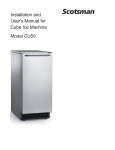
MDT3F and MDT4F Manual
Purpose of this manual: To provide detailed
installation and operation instructions; to give
insights into how the machine works; to list
possible causes for problems; and to suggest
procedures for specific types of service.
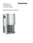
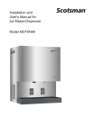
The MDT3F and MDT4F are combination ice
makers and dispensers. The refrigeration system
is air cooled, using R-134a as a refrigerant. The
control system uses electric eyes as a bin control
and a water level sensor as the water safety
control. As ice is made, it fills a plastic storage bin.
When ice is needed, a motor rotates a stainless
steel vane inside the storage bin and sweeps the
ice into the spout.
New Table of Contents
Specifications: · · · · · · · · · · · · · · · · · · · · · · · · · · · · · · · · · · · · · · · · · · · Page 2
To The Installer: · · · · · · · · · · · · · · · · · · · · · · · · · · · · · · · · · · · · · · · · · · Page 3
For The Electrician · · · · · · · · · · · · · · · · · · · · · · · · · · · · · · · · · · · · · · · · Page 4
For The Plumber · · · · · · · · · · · · · · · · · · · · · · · · · · · · · · · · · · · · · · · · · Page 5
Wall Mount Kit (KWB4): · · · · · · · · · · · · · · · · · · · · · · · · · · · · · · · · · · · · · · Page 6
Final Check List & Initial Start Up · · · · · · · · · · · · · · · · · · · · · · · · · · · · · · · · · Page 7
User Operation · · · · · · · · · · · · · · · · · · · · · · · · · · · · · · · · · · · · · · · · · · Page 8
Component Location & Function · · · · · · · · · · · · · · · · · · · · · · · · · · · · · · · · · Page 9
Refrigeration System Operation · · · · · · · · · · · · · · · · · · · · · · · · · · · · · · · · · · Page 10
Water System Operation: · · · · · · · · · · · · · · · · · · · · · · · · · · · · · · · · · · · · · Page 11
Mechanical Operation · · · · · · · · · · · · · · · · · · · · · · · · · · · · · · · · · · · · · · · Page 12
Electrical Sequence · · · · · · · · · · · · · · · · · · · · · · · · · · · · · · · · · · · · · · · · Page 13
Maintenance: · · · · · · · · · · · · · · · · · · · · · · · · · · · · · · · · · · · · · · · · · · · Page 14
Dispense Area Sanitation · · · · · · · · · · · · · · · · · · · · · · · · · · · · · · · · · · · · · Page 15
Auger and Bearing Inspection · · · · · · · · · · · · · · · · · · · · · · · · · · · · · · · · · · · Page 16
Inspection: Top Bearing · · · · · · · · · · · · · · · · · · · · · · · · · · · · · · · · · · · · · · Page 17
Inspection:· · · · · · · · · · · · · · · · · · · · · · · · · · · · · · · · · · · · · · · · · · · · · Page 18
Service Diagnosis · · · · · · · · · · · · · · · · · · · · · · · · · · · · · · · · · · · · · · · · · Page 19
Service Diagnosis · · · · · · · · · · · · · · · · · · · · · · · · · · · · · · · · · · · · · · · · · Page 20
Service Diagnosis: Circuit Board · · · · · · · · · · · · · · · · · · · · · · · · · · · · · · · · · Page 21
Removal and Replacement · · · · · · · · · · · · · · · · · · · · · · · · · · · · · · · · · · · · Page 22
Water System · · · · · · · · · · · · · · · · · · · · · · · · · · · · · · · · · · · · · · · · · · · Page 23
Bearings, Water Seal and Auger · · · · · · · · · · · · · · · · · · · · · · · · · · · · · · · · · Page 24
Top Bearing Replacement · · · · · · · · · · · · · · · · · · · · · · · · · · · · · · · · · · · · · Page 25
Water Seal & Bottom Bearing Replacement: · · · · · · · · · · · · · · · · · · · · · · · · · · · Page 26
Refrigeration System · · · · · · · · · · · · · · · · · · · · · · · · · · · · · · · · · · · · · · · Page 27
Gear Reducer Removal · · · · · · · · · · · · · · · · · · · · · · · · · · · · · · · · · · · · · · Page 28
Auger Drive Motor · · · · · · · · · · · · · · · · · · · · · · · · · · · · · · · · · · · · · · · · · Page 29
Note this symbol when it appears.
It marks a possible hazard.
April 2010
Page 1
MDT3F & MDT4F
Specifications:
Scotsman ice machines, like the MDT3F or
MDT4F, are designed to be installed indoors, in a
controlled environment. The minimum and
maximum operating conditions are:
· Minimum Air Temperature: 50oF.
· Maximum Air Temperature: 100oF.
· Minimum Water Temperature: 40oF.
· Maximum Water Temperature: 100oF.
· 60 Hz voltage may vary between 104 and 126
volts.
· Water Pressure may vary between 20 and 80
psi.
Operating the machine outside these conditions
constitutes misuse and voids the warranty.
Specifications:
Model Number
MDT4FA-1
MDT4FA-6
MDT3FA-1
MDT3FA-6
Dimensions
W" x D" x H"
Basic
Electrical
14 x 237 8 x 34¼
14 x 237 8 x 34¼
14 x 237 8 x 34¼
14 x 237 8 x 34¼
115/60/1
230/50/1
115/60/1
230/50/1
Scotsman Ice Systems are designed and
manufactured with the highest regard for safety
and performance. They meet or exceed the
standards of UL, NSF and CUL.
Scotsman assumes no liability or responsibility of
any kind for products manufactured by Scotsman
that have been altered in any way, including the
use of parts and/of other components not
specifically approved by Scotsman.
Scotsman reserves the right to make design
changes and/or improvements at any time.
Specifications and designs are subject to change
without notice.
Refrigerant
Charge
(R134a)
14 oz.
14 oz.
12 oz.
12 oz.
April 2010
Page 2
Min.
Circuit
Ampacity
15.1
7.5
9.4
5.3
Max Fuse
Size
20
15
15
15
MDT3F & MDT4F
To The Installer:
A professional installation of any product is critical
to the long term satisfaction of the user. The ice
maker-dispenser is designed to be installed either
on a counter, or, using a wall hanging kit, hung
from a wall.
Determine the location from the anticipated use
and any options planned for.
This machine is air cooled and blows air out the
lower left side of the cabinet. Do not install the
machine where the side to side air flow might be
blocked.
Cooling Air Flow
Water Quality:
The quality of the water supplied to the machine
will directly affect the purity of the ice and the
reliability of the machine. While the condition of the
water supplied to a building is normally out of the
control of the user, water can be treated at the
point of use.
There are two major types of water impurities:
suspended solids (those that are carried along with
the water and may be filtered out) and dissolved
solids (those that are part of the water and have to
be treated). A water filter is always a good idea,
but does require regular maintenance to change
the cartridge. In some water conditions, water
treatment may be required. Generally this means a
polyphosphate feeder of some kind. Water
softeners are not recommended.
General Installation:
Place the machine in its final location. Remove the
front, top, right and left side panels:
1. Remove two screws at the bottom of the front
panel.
Cooling Air
Flow
2. Disconnect wires at water switch.
3. Remove two screws at the front of the top panel,
then lift the top panel up to remove it.
4. Remove screws from the sides (top and bottom)
of the side panels and from the splash panel.
5. Pull the side panels back and off the machine.
Warm Air
Exhaust
The machine will require electrical power, water
and a drain. Follow all local codes. Rough in the
utilities before placing the machine into position
(see For The Electrician and For The Plumber).
Plumbing connections may be made thru holes in
the back of the cabinet or thru the base.
· Route the sink drain to the back of the cabinet.
Route the bin drain to the back panel.
· Route the electrical power cord from the
junction box inside the cabinet. thru the back
panel .
· Route the inlet water line thru the back panel or
base to the flare fitting inside the cabinet.
After all plumbing and internal wiring has been
done, replace the side and back panels.
Level the unit front to back and left to right.
The machine does not require sealing to the
counter due to the gasket on the base.
April 2010
Page 3
MDT3F & MDT4F
For The Electrician
Electrical connections:
Check the nameplate for voltage and current
requirements. An electrical cord is not supplied.
Connect the MDT3F or MDT4F to a separate
electrical circuit. Wiring to the machine must
conform to all codes. A licensed electrician may be
required in some situations.
Remove the back panel to make the electrical
connection. The electrical connection is made on
the terminal strip in the junction box inside the
machine. Replace the back panel when the
electrical connections are complete.
FOLLOW ALL APPLICABLE LOCAL, STATE
AND NATIONAL CODES
This Unit MUST BE GROUNDED
Electrical
Power
Remove Back Panel To
Expose Junction Box
May 2001
Page 4
MDT3F & MDT4F
For The Plumber
Drains:
The dispenser requires a gravity drain. The pitch
on the drain tubes must be at least ¼ inch fall per
foot of horizontal run. On long horizontal runs, a
vent at the back of the cabinet will improve
draining, and is recommended.
There are two drains to connect: A sink drain, a 7 8”
ID plastic tube; and the bin drain, a 5 8” ID plastic
tube. Install rigid tubing between the machine and
the building drain. Route the drains separately to
the building drain.
Water supply:
FOLLOW ALL APPLICABLE LOCAL, STATE
AND NATIONAL CODES
Connect cold, potable water to the machine. The
inlet water fitting is a 1/4" male flare located on a
wall inside the cabinet.
Water Inlet Fitting - 1/4"
Male Flare
(Inside Cabinet)
A hand valve near the
location is
recommended. A water
filter is also a good
idea.
Follow all local codes.
Strainer or
Filter
Water Supply
Bin and Reservoir
Overflow Drains
Sink Drain
Building Drain
(Typical)
May 2006
Page 5
MDT3F & MDT4F
Wall Mount Kit (KWB4):
Contents:
Top Wall Bracket:
1. Top Case Hanger Bracket: Attaches to the frame
of the dispenser.
1. Hold the bracket on the wall where it will be
mounted.
2. Top Wall Bracket: Mounts to the wall and
engages the top case hanger bracket to support
the dispenser.
2. Mark on the wall the positions of the holes in the
bracket.
3. If needed, drill pilot holes for the fasteners.
3. Bottom Wall Bracket: Mounts to the wall and
spaces the base of the dispenser away from the
wall.
4. Secure the bracket to the wall with fasteners of
sufficient strength to hold up the dispenser.
4. Bottom Fittings Cover: Fastened to the bottom
wall bracket to hide the utility connections.
Connect all internal utilities. Route tubes and
wires out the bottom.
5. Junction box cover.
Junction box cover. Install on the junction box.
Bottom Wall Bracket:
1
1. Lift up and hang the dispenser from the top wall
bracket.
2. Position the bottom wall bracket so that the
molding on the dispenser base bottoms in the
channel of the wall bracket.
2
3. Secure the bracket to the wall.
Bottom Fitting Cover:
5
1. Connect electrical power, water inlet, bin drain
and sink drain of the dispenser thru the bottom of
the case.
3
2. Secure bottom fitting cover to the bottom wall
bracket with the four sheet metal screws provided
in this kit.
Top Case
Bracket
4
Installation: Check building wall for the strength
required to support a machine of this weight and
size. Note that if at least 6" of space is not left
above the machine, cleaning and most service of
the machine will require removal of the machine
from the wall mounts. All utilities are to be routed
thru the base. The back panel is not used when
the machine is hung from the wall.
Top Case Hanger Bracket
Wall
Brackets
Bottom
Cover
1. Remove back panel.
2. Place top hanger bracket on the inside of the
frame and position it in line with the pre-punched
holes in the frame.
3. Fasten the bracket to the frame with four ¼ - 20
screws from the kit.
Secure With
Screws
May 2001
Page 6
MDT3F & MDT4F
Final Check List & Initial Start Up
1. Is the machine located indoors where the
temperature limitations are not exceeded?
Initial Start Up
1. Remove 2 screws at the bottom of the front
panel and remove the front panel.
2. Is there at least 6" clearance on both sides of
the cabinet for adequate air flow?
2. Remove screws and the top panel.
3. Is the water supply adequate, and has a shut off
valve been installed?
4. Is the cabinet level?
5. Have all of the electrical and drain connections
been made?
3. Open the water supply shut off valve.
4. Watch the water fill the reservoir. Check that it
flows in and fills the reservoir near to the mark
molded into the side of the reservoir. Check that
the float shuts off the water flow when the tank is
full. Check for leaks. Tighten hose clamps as
needed.
5. Plug the unit in or switch on the electrical power.
After about 15 seconds the machine should start.
6. Let the machine operate, listen for any unusual
noises. If needed, reposition tubing & panels to
eliminate vibration.
After the unit has been operating for about 10
minutes, there should be enough ice in the bin to
test the dispense system.
7. Using a container, place in in front of the glass
sensor and below the ice chute. See that ice is
dispensed (the bin drive motor continues to run as
long as the container is in place).
8. Move the water switch (rocker switch on the
front panel) to ON. Place the container in front of
the glass sensor and under the ice chute. Both
water and ice should be dispensed.
9. Pour water into the sink and check that the drain
does not leak but drains the water rapidly.
10. Explain to the user the maintenance
requirements and operation of the machine.
11. Fill out the Warranty Registration and
Customer Evaluation form. Mail it to Scotsman.
12. Leave the service manual with the owner/user
and explain who should be called if service is
needed.
April 2010
Page 7
MDT3F & MDT4F
User Operation
The MDT3F and the MDT4F are automatic ice
vending machines. All either requires is cool air,
clean water and an adequate supply of electrical
power.
To Vend Ice:
Place a container in front of the Touch Free sensor
and below the ice spout. Hold it there until the
container is full of ice. Do NOT overfill the
container or a build up of ice in the sink or a back
up of ice in the spout will occur.
To Vend Ice and Water.
Switch the Water Switch to ON. Place a container
in front of the Touch Free sensor and below the ice
spout. Water and ice will be dispensed into the
container below the spout. Note: The water is NOT
cooled, it is the same temperature as the building
supply water.
Daily Maintenance: Pour hot water into the sink to
flush out any debris or build up. Wipe the cabinet
off, wash the sink and grill to keep minerals from
accumulating.
Caution:
Unless the touch free sensor is
de-activated by pushing the
Cleaning Switch in, ice and/or water
may be dispensed during cleaning.
The Cleaning Switch is a button,
located to the left of the ice chute,
that temporarily shuts off the sensor
for cleanup of the splash panel.
Pushing the button in will disable the
sensor for 2 minutes, pushing the
button in again will return the sensor
to normal operation.
Water
Switch
Glass
Sensor
Touch Free
Disable
Switch
May 2001
Page 8
MDT3F & MDT4F
Component Location & Function
Evaporator. This is a vertical cylinder full of water
and refrigerated. Also in the cylinder is a slowly
rotating auger. The auger forces the ice up the
evaporator walls and compresses it at the top. The
resulting flaked ice then falls by gravity into the ice
storage bin.
Water Reservoir. The water reservoir contains the
inlet float valve and the water level sensor. The
float valve controls the flow of water into the
reservoir, and the water level sensor will stop the
ice maker if the water supply fails.
Ice Storage Bin. The ice storage bin is an
insulated plastic container that is open at the top
and has a spout at the bottom. There is a rotating
ice vane inside the bin that causes the ice to be
swept over the spout and dispensed. The vane is
rotated by a gear motor at the top of the bin.
Bin Cover. The bin cover not only keeps dirt from
the ice storage bin, it also is the support for the
dispense gear reducer and the location of the
electric eye bin controls.
Auger Drive
Condenser. The machine uses
an air cooled condenser. It blows Compressor
air out, away from the fan motor.
The heat removed from the water
is exhausted from the condenser.
Water Reservoir
Evaporator
Bin Cover
Compressor. The refrigeration
system compressor provides the
force to move the refrigerant
around the system.
Auger Drive. The auger drive is
a direct drive gear reducer.
Ice Storage
Bin
Condenser
May 2001
Page 9
MDT3F & MDT4F
Refrigeration System Operation
Both the MDT3F and the MDT4F use a forced draft
condenser, capillary tube and hermetic
compressor. The system uses R-134a as a
refrigerant. High pressure, high temperature
refrigerant is forced thru the condenser where it
looses enough heat to condense. The high
pressure liquid refrigerant then passes thru the
capillary tube which causes a pressure drop in the
evaporator. As the high pressure liquid refrigerant
moves into the evaporator’s area of low pressure,
the warm water and low pressure cause the
refrigerant to evaporate and absorb heat from the
metal walls of the evaporator. After the refrigerant
has flowed thru the evaporator it goes back to the
compressor thru the suction line as a low pressure
vapor. At the compressor the cycle is repeated.
System Characteristics:
· Typical Low Side Pressure:
13 - 14 PSIG
· Typical Discharge Side Pressure:
135 - 175 PSIG
Evaporator
Capillary Tube
Dryer
Compressor
Refrigeration System Schematic
Air Cooled
Condenser
May 2001
Page 10
MDT3F & MDT4F
Water System Operation:
The water system consists of a float valve,
reservoir and water dispense solenoid valve. The
water level in the reservoir tank is the same level
as that inside the evaporator. Building water supply
flows to both the float valve and the solenoid. The
float valve will open to add water to the reservoir
as water flows out to the evaporator. The solenoid
will only open if the water switch is closed and the
touch free sensor initiates an ice dispense.
Electric Eyes
Inside the evaporator there is a water seal. This
seal is the type that has a rotating half and a
stationary half. The area where the two seals touch
are smooth flat surfaces. When the auger is
installed in the evaporator, it forces the rotating half
of the seal against the stationary half. The
stationary half is spring-loaded and provides a firm
pressure against the auger portion of the seal.
Water Level
Sensor
Evaporator
Float Valve
Ice
Dispensing
Vane
Water Seal
Inner Bin
Bottom
Bin and
Reservoir
Overflow
Drain
Water and Ice
Dispensing Spout
Water Inlet
Connection
Water Dispensing
Solenoid Valve
Sink
Water System Schematic
Sink Drain
April 2010
Page 11
MDT3F & MDT4F
Mechanical Operation
General:
The machine makes, stores and dispenses ice. It
also dispenses water. The ice making portion of
the machine produces flaked ice at about 32 oF.
The ice falls thru a chute into the dispensing bin.
Above the cylindrical bin is a dispense drive motor
and electric eyes. The drive motor is connected to
an ice vane in the bin. When the user holds a
container in front of the glass sensor and below the
ice chute, the dispense drive motor rotates the
vane and the ice. There is a slot in the base of the
bin, located just above the vend spout and glass
filler lever. When the ice moves over that slot,
some of the ice on the bottom of the bin falls thru
the slot, into the chute and fills the container.
Ice Vending
ON/OFF Control:
Dispensing continues until the beam is no longer
reflected back to the sensor.
Dispensing takes place when the touch free
sensor’s infrared beam bounces back to the
sensor from a container placed directly in front of
the sensor and under the ice chute.
When the beam is reflected back, it signals the
circuit board to connect power to the dispense
drive motor, and ice is then moved over the slot in
the base of the bin, where it falls by gravity thru the
chute into the container.
If the Water switch is On, water is also dispensed
at the same time.
Flaked ice is produced by the ice maker until ice
builds up between the electric eyes. When the
electric eyes can no longer “see” each other, they
send a signal to the control board to shut the
machine off. The refrigeration compressor stops
but the auger drive motor will continue to operate
for about 2 minutes to clear the evaporator of ice.
Water Control:
Because water is such an important requirement
for making ice, a water level sensor has been
placed in the reservoir. If the water supply to the
machine should fail, the water level sensor will
send a signal to the control board to shut down
the machine.
Refrigeration:
The refrigeration system uses a hermetic
compressor (specifically designed for R-134a),
forced draft air cooled condenser, capillary tube
and vertical flaked ice evaporator. Inside the
evaporator is a slowly rotating auger. The auger is
supported by bearings at each end, and there is a
face-type water seal above the bottom bearing.
The auger is driven by a 1/10 HP direct drive gear
reducer. The auger drive motor has a speed
operated switch on it that will keep the compressor
from operating if the auger motor is not turning at
full speed.
Water System
Water flows from the building supply to the
reservoir and to the electric solenoid valve. Water
from the reservoir is used to make ice. Water the
flows thru the solenoid is dispensed.
The bin, sink and reservoir overflow all have
drains.
April 2010
Page 12
Touch Free Sensor
MDT3F & MDT4F
Electrical Sequence
Refer the wiring diagram as needed.
Shut Down consists of:
· The compressor contactor opens
The “Power” light on the board glows whenever
there is power to the machine (and the master
switch is ON).
· The compressor stops
· The auger motor is run by the circuit board for 2
Switching the power on does the following:
· The bin empty and power lights on the circuit
board glow.
more minutes, clearing out ice in the evaporator,
and then
· The auger motor no longer receives power from
· There is a 15 second delay
· If there is enough water in the reservoir, the
circuit board will allow the machine to start up.
Start up consists of:
· The compressor contactor coil receives power
from the circuit board.
· The contactor is energized, connecting power to
the compressor, and the compressor starts.
· The auger motor receives power from the circuit
board and starts.
· As ice goes past the ice level sensors, the bin
empty light will stay on and the machine will
continue to run, unless the ice stays between
the sensors for more than 15 seconds (bin full).
At that point, the bin empty light goes out, and
the machine shuts down.
Other reasons for shut down:
· Low water level (as sensed by the thermistor in
the reservoir).
the circuit board, and the auger motor stops.
After a 6 minute delay, If the ice level sensor is
clear (bin empty) for more than 15 seconds, the
machine will start up again.
Another purpose of the circuit board is to turn the
machine off if there is not enough water in the
machine.
· When the water level in the reservoir falls
below the tip of the water level sensor, the
machine will “shut down”
· After a 6 minute delay, if the water refills the
reservoir, the machine will start up again.
Ice Vending
· When a user places a container in front of the
Touch Free ice sensor and below the ice
delivery chute, the circuit board connects power
to the bin drive motor and ice is dispensed for
as long as the container is present. If the user
does not remove the container, ice will be
dispensed for 60 seconds and then stop.
· When a user selects water and ice dispensing,
water is also dispensed with the ice.
Splash panel cleaning:
A switch, located to the left of the spout, may be
pushed to disable the Touch-Free sensor for
splash panel cleaning. It automatically resets after
2 minutes, or, if pushed within the 2 minutes, resets
the circuit board to enable the Touch Free sensors.
April 2010
Page 13
MDT3F & MDT4F
Maintenance:
Although the ice in this dispenser is completely
untouched, the water and ice vending systems will
need to be periodically sanitized and
de-mineralized. The air cooled condenser will also
need to be kept clean.
Schedule the sanitation, cleaning and
de-mineralization on a regular basis to keep the ice
clean and the machine operating efficiently.
Sanitation and Cleaning
1. Vend all ice from the machine.
12. Repeat steps 3-11, except substitute a locally
approved sanitizing solution for the cleaner. A
possible sanitizing solution may be obtained by
mixing 1 ounce of household bleach with 2 gallons
of clean, warm (95oF.-115oF.) water.
2. Remove top and right side panels.
13. Unplug or disconnect electrical power.
3. Unplug or disconnect electrical power.
14. Remove bin top, pour in warm potable water to
melt out any ice.
Water System:
This ice machine requires periodic sanitation and
de-mineralization.
4. Shut off water supply.
15. Pull out the vane and bin bottom from the bin.
5. Drain reservoir.
6. Mix 8 ounces of Scotsman Ice Machine Cleaner
and 3 quarts of hot (95oF. -115oF.) potable water.
16. Thoroughly wash the bin’s interior, bin top
interior, spout, ice vane and bin bottom with the
sanitizing solution. Pour some down the bin drain.
17. Reassemble the bin bottom, vane and bin
cover.
Scotsman Ice Machine
Cleaner contains acids.
These compounds may
cause burns.
If swallowed, DO NOT
induce vomiting. Give
large amounts of water or
milk. Call Physician
immediately. In case of
external contact, flush
with water.
KEEP OUT OF THE
REACH OF CHILDREN.
18. Wash the sink area with the sanitizing solution
and pour sanitizing solution down the sink drain.
19. Replace all panels and reconnect water and
electrical power.
Air Cooled Condenser:
1. Disconnect electrical power.
2. Remove top panel
3. Remove right and left side panels.
4. Use pressurized air to blow the lint from the
outside of the condenser in towards the fan motor.
A vacuum cleaner hose placed on near the fan
motor should pick up most of the dust. Check for
interior dirt. If needed, use coil cleaner to
de-grease the condenser.
7. Pour the water into the reservoir.
8. Wait 15 minutes for the cleaner to dissolve the
minerals inside the evaporator.
9. Plug in the machine or reconnect electrical
power.
10. As the machine operates, pour in the balance
of the cleaning solution.
5. Replace all panels and reconnect electrical
power.
11. Reconnect water supply, operate the machine
for 15 more minutes, then switch it off.
May 2001
Page 14
MDT3F & MDT4F
Dispense Area Sanitation
1. The spout may be removed by taking out the
two mounting screws. Wash and sanitize it.
2. The sink grill may be removed for washing and
sanitizing.
3. The sink should be flushed with hot water and
wiped clean with sanitizer.
4. The splash panel requires special attention to
clean it.
· Push and release the Cleaning Switch located
to the left of the ice spout. This disables the
Touch Free Sensor so the splash panel may be
cleaned without vending ice or water.
· Wash the splash panel and wipe with sanitizer.
· Re-push the clean switch or allow 2 minutes to
pass for the Touch Free system to reset.
Push Touch Free Sensor
Disable Button Before
Wiping Splash Panel
Pour Hot Water Into Sink
Regularly To Keep Drain
Line Open
April 2010
Page 15
MDT3F & MDT4F
Auger and Bearing Inspection
While in most areas regular in-place cleaning with
Scotsman scale remover will be adequate to keep
the interior of the evaporator free of excessive
mineral build up, some water conditions may
require more intense methods. In addition, the
auger bearings require physical inspection to
determine that they are not wearing. This physical
inspection is recommended twice per year for the
top bearing and once per year for the auger and
both bearings.
If the auger still will not move, bearing replacement
is mandatory. See Bearing Removal and
Replacement.
Cap
Cap Screw
Top Bearing
Set
Whenever the auger is removed, replacement of
the water seal is recommended.
Breaker
Screws
If a bearing requires replacement, the other
bearing must also be replaced.
Breaker
Note: The bearing design changed in April
2010. These directions are for removal of the
auger and apply to all versions
Auger
1. Unplug or disconnect electrical power.
Rotating Parts Hazard
Disconnect Electrical
Power Before Beginning
2. Shut off the water supply.
3. Remove top panel.
4. Remove right side panel.
5. Drain the evaporator and reservoir.
6. Remove cap from top of evaporator.
Water Seal
Bottom
Bearing
7. Remove 2 permagum plugs from the side of the
evaporator.
8. Remove 2 screws (screwheads were covered by
the permagum).
Coupling
9. Pull up on:
a) Design from 2001 to 2007: The pull ring to
remove the auger.
b) Design from 2007 on: Obtain a 1 1/2" pipe
thread tee. Install the Tee, it will screw onto the
breaker. Pull up on the Tee or insert a bar thru the
Tee and pull up on it to remove the auger and top
bearing retainer. If it is difficult to pull:
· Design from 2001 to 2007: Remove the breaker
cover by taking the snap ring out.
· All versions: Unscrew the auger bolt.
· All versions: Use threaded rod or a slide
Adapter
Stand
hammer puller and screw into the auger, slide
the weight quickly up against the stop to remove
the auger.
April 2010
Page 16
MDT3F & MDT4F
Inspection: Top Bearing
This procedure applies to machines produced after
April 2010.
1.Shut machine off by disconnecting electrical
power.
2. Remove top panel.
3. Unscrew and remove bearing sealing cap
Top of Bearing Thrust Washer
Sealing Cap
4. Check the top bearing. The top of the thrust
washer will be visible. It should be clean, as seen
in the photo.
5. Remove the bolt and thrust washer and check
the bearing surface for adequate grease. Grease
should just cover the bearing surface. Wipe out
any contaminated grease. Add new grease,
Scotsman part number 19-0662-02. If water or rust
is present, replace the bearing.
Thrust Washer and Bearing
6. Check the bottom of the evaporator for water
leaks. Some condensation is normal, however
visible water may be a sign of a water seal leak.
7. Reverse all of the above to reassemble
Note; The bottom bearing must be removed from
the evaporator when replacing the water seal. See
page 25.
Thrust Bearing Surface
April 2010
Page 17
MDT3F & MDT4F
Inspection:
Photo-Electric Eyes
The photo electric eyes used to “see” the ice build
up in the top of the bin cover must be clean to get
a good “look” at the ice. If clouded by mineral
scale, the eyes will cause the ice machine to shut
off and stay off.
To clean the photo-electric eyes.
1. Remove the top panel.
2. Pull both of the photo-electric eyes out of their
rubber grommets.
3. Wash both eyes with a clean cloth dipped in
Scotsman Ice Machine Cleaner.
Clean Photo-Electric
Eyes
4. Wash the eyes off with clean water.
5. Replace the eyes in the grommets
6. Replace the top panel
Water Level Sensor
The water level sensor may not shut the ice
machine off when the reservoir goes dry if there is
a film of mineral scale on the probe tip.
1. Remove the top panel.
2. Remove the reservoir cover.
3. Pull the water level probe up and out of the
reservoir.
4. Carefully wipe the tip of the probe with a clean
cloth. Ice machine cleaner may be needed.
Note: The tip is made of glass.
5. Reinsert the water level sensor in the reservoir.
Clean Water Level
Sensor
6. Replace the reservoir cover and the top panel.
Coupling
Use the grease zerk on the side of the coupling to
add grease once per year.
That concludes normal maintenance. If the fan
motor has an oil plug, it may be oiled after 10
years of operation.
May 2001
Page 18
Water
Reservoir
MDT3F & MDT4F
Service Diagnosis
PROBLEM
No ice is dispensed.
POSSIBLE CAUSE
No ice in bin due to:
· No electrical power
· Overuse
· Water supply turned off
· Bin controls dirty
· Water sensor dirty
· Control system malfunction
· Auger drive motor open
· Centrifugal switch open
· Auger does not turn
· No refrigeration
PROBABLE CORRECTION
Check/restore power
Recheck ice needs vs. machine
capacity.
Check water filter/hand valve/float
valve
Check & clean bin control (electric
eyes)
Check & clean water sensor
Check control system
Check auger drive motor
Check centrifugal switch
Check coupling & gear reducer
Check refrigeration system
Ice in bin, but will not dispense:
Drive motor does not turn
· Vend system does not work
· Dispense motor open
· Dispense output shaft broken
Check/replace vend system
Check that cleaning switch has
been released.
Check/replace dispense motor
Check/replace output shaft
Ice in bin, motor turns vane.
Ice jammed up
· Users held cup against
Advise owner/manager to instruct
users.
· Bin bottom slot not over spout
· Ice will not slide down bin wall,
Check bin bottom position
· Wet ice in the bin from high
Check water level, check suction
and discharge pressures
dispense spout and jammed
unit.
bin out of round.
water level or high suction
pressure
May 2001
Page 19
Check bin interior wall for rough
texture or out of round.
MDT3F & MDT4F
Service Diagnosis
PROBLEM
Unusual noise
POSSIBLE CAUSE
Mineral scale in evaporator
Auger coupling dry
Auger coupling worn
No water is dispensed
Water drips from spout
Ice will not stop dispensing
Water leaks from cabinet
No refrigeration
Bearings worn
Gear motor loose on frame
Low water level
Tubing vibrating
Tooth on a gear missing
Compressor too loud
Gear noise
Water Switch in Off position
Water switch open
Water solenoid plugged up
Water solenoid coil open
Vend system does not work
Water turned off
Melting ice in chute
Unit or bin not level
Water solenoid leaks thru
Ice jammed in spout
Vend system does not work
Evaporator water seal worn or
cracked
Tubing to evaporator leaks
Drain leaks
External drain restricted
Gear motor does not turn
Centrifugal switch does not close
Fan motor does not turn
Lack of refrigerant
Compressor does not pump
May 2001
Page 20
PROBABLE CORRECTION
Clean water system with ice
machine cleaner.
Grease coupling
Replace coupling and adapter
stand.
Replace bearings and water seal.
Tighten bolts, check grommets
Check water level in reservoir
Check tubing for contact
Check gears in auger drive
Replace compressor
Check gear motor for oil leak
Switch to ON
Replace switch
Clean inlet screen of solenoid
Replace solenoid
Check/replace vend system
Restore water supply
Some water dripping is normal
Level unit, check bin
Replace solenoid
Clear ice jam, check for cause
Check/replace vend system
Replace seal and bearings
Replace tubing/fittings
Check drain tubes and fittings
Clean out drain
Check motor
Check switch
Check fan motor
Add refrigerant, if problem is
reduced, locate leak and repair it.
Check/replace start capacitor
Check/replace start relay
Check/replace compressor
MDT3F & MDT4F
Service Diagnosis: Circuit Board
1
2
3
4
Explanation of Indicator Light
On at all times when the master switch is ON and machine is
connected to electrical power.
Position On
Board
1
Name and Meaning of
Light or Reset
Power,
ON = Normal
On when ice level is low (unit making ice).
2
Bin Empty,
ON = Needs Ice
Normal 6 minute off/delay start. To prevent short cycling, the
machine will not restart after any shut off (except power to the
board) until 6 minutes have passed.
3
Off Timer,
ON = Unit cycling off
On when water level is low in the reservoir.
4
No Water,
ON = Trouble
To check the electrical system, first check the lights on the circuit board.
1. Remove the top panel.
2. Remove the left side panel.
3. Remove the control box cover.
May 2001
Page 21
Scotsman MTD3, MDT4, MDT5, MDT6
Service Diagnostic - Touch Free and Control System
The MDT controller operates the refrigeration and dispensing systems. The on/off of the ice making
system is determined by infrared sensors. Ice or water dispensing is also determined by infrared
sensors. Additionally there is a safety sensor, the water level sensor, that prevents operation if there
isn’t any water in the reservoir.
1. Confirm line voltage is being supplied to terminals 1 and 15.
2. No ice, No Water light is On, water in reservoir. This is typically caused by a dirty tip on the water
level sensor. If the tip is clean and undamaged, check for voltage at the Water Sensor pins, it
should read about 12 volts DC. If no voltage, replace the controller. If there is voltage, replace
the sensor. Another check is sensor resistance, the sensor normally reads about 850 ohms at 72
degrees F., higher if colder and lower if warmer. There is no bypass method or part that will allow
operation, only a good sensor will work.
3. Ice is not dispensed when a container is in front of the sensor. First try a non-clear container,
as the sensors infrared light can be absorbed by clear glass. Second, unplug the sensors at the
Dispense connection and jump the two outside pins. The ice dispense relay should engage and
supply power to the dispense motor. If it does not, replace the controller. If it does, replace the
sensors.
Line Voltage
Jump outside pins to
test ice dispense relay
12 volts DC
291-8
MDT3F & MDT4F
Removal and Replacement
Panels:
Dispense Vane
1. Remove two screws at the back of the top
panel.
1. Disconnect electrical power.
Dispense Drive
Motor
2. Lift up at the back and push the top panel
forward to release it.
Bin Top
3. Remove 3 screws at the top, 3 screws at the
bottom and 1 screw at the front edge of each side
panel.
4. Push each side panel to the rear to release the
panel from the cabinet frame.
Dispensing System
The dispensing system consists of the vend
switch, dispense motor, dispense vane, bin bottom
Electrical Shock Hazard.
Disconnect electrical
power before beginning.
2. Remove top panel.
and bin.
Dispense Gear Motor
3. Remove four thumb screws holding bin cover to
bin.
1. Disconnect electrical power.
4. Lift bin cover off bin. Set aside.
2. Remove top panel.
5. Grasp the ice vane and pull it straight up.
3. Remove one screw holding ground strap to
cabinet frame.
6. Reverse to reassemble.
Bin Bottom.
4. Cut off two dispense motor wire nuts.
Perform steps 1-5 above (to remove the dispense
vane).
5. Remove screws holding dispense drive gear
motor to the bin top.
1. Lift bin bottom out of the dispense bin.
6. Pull gear motor off the bin top.
2. When replacing, be sure that the slot on the bin
bottom is over the dispense chute (at the front).
7. Unscrew the output shaft extension from the
gear motor.
8. Remove screws holding the mounting bracket to
the gear motor.
9. Reverse to reassemble, be certain that the new
wire nuts are secure and that the ground strap is
reattached.
May 2001
Page 22
MDT3F & MDT4F
Water System
The water system consists of the reservoir and
inlet water valve.
Valve Plunger
1. After the valve has been removed from the
reservoir, remove the nut holding the valve to its
mounting bracket.
Reservoir.
1. Shut off the water supply.
2. Pull out the cotter pin to release the internal
valve plunger.
2. Remove the top panel.
3. Remove the right side panel.
Note: Do not replace the plunger if the valve’s seat
is damaged. Replace the valve.
4. Drain the water reservoir and evaporator.
Inlet Water Valve.
5. Disconnect inlet and outlet tubes from the
reservoir.
1. Disconnect electrical power.
6. Remove screws holding reservoir to its mounting
bracket.
2. Shut off the water supply.
3. Remove the top panel.
7. Remove reservoir from the machine.
4. Remove the right side panel.
8. Reverse to reassemble.
5. Remove wire harness from inlet water valve.
Float Valve
6. Remove tube connecting outlet of the valve to
the dispense tube.
1. Shut off the water supply.
2. Remove the top panel.
3. Remove the reservoir cover.
7. Rotate the valve to unscrew it from its inlet
fitting.
4. Remove the water inlet tube.
8. Reverse to reassemble.
5. Push in the mounting tabs at the back of the
reservoir and lift the valve out of the reservoir tank.
6. Replace with a new valve or replace the valve
plunger.
Plunger
Valve
Water Level
Sensor Slot
May 2001
Page 23
MDT3F & MDT4F
Bearings, Water Seal and Auger
1. Disconnect electrical power.
Rotating Parts Hazard
Disconnect Electrical
Power Before Beginning
Cap
2. Shut off the water supply.
Cap Screw
3. Remove the top panel.
4. Remove the side panels.
Top Bearing
Set
5. Drain the reservoir and evaporator.
Breaker
Screws
6. Remove cap from the top of the evaporator.
Breaker
7. Remove the two permagum plugs from the side
of the evaporator.
8. Remove auger
Auger
a) Models prior to 2007: Pull up on the ring to lift
the auger out of the evaporator.
b) Design from 2007 on: Obtain a 1 1/2" pipe
thread tee. Install the Tee, it will screw onto the
breaker. Pull up on the Tee or insert a bar thru the
Tee and pull up on it to remove the auger and top
bearing retainer.
If it is difficult to pull:
· Design from 2001 to 2007: Remove the breaker
cover by taking the snap ring out.
· All versions: Unscrew the auger bolt.
· All versions: Use threaded rod or a slide
hammer puller and screw into the auger, slide
the weight quickly up against the stop to remove
the auger.
9. Separate auger from top bearing:
a) Units prior to 2007: Remove snap ring holding
bearing cover to breaker.
Coupling
a1) Remove bearing cover.
All units: Unscrew bolt holding bearing to auger.
9. Remove three cap screws holding evaporator to
the adapter stand. Separate stand from evaporator.
10. Tap the water seal and bottom bearing out of
the bottom of the evaporator.
11. Replace the bearings and water seal. Replace
the auger if the splines are damaged. Replace the
evaporator if more than 1/3 of the vertical rifle
grooves are gone. Sand or hone and sand the
inside of the evaporator if mineral build up is
heavy.
April 2010
Page 24
Adapter
Stand
MDT3F & MDT4F
Top Bearing Replacement
Units from 2001 to April 2010: The top bearing was
two ball bearings, one on top the other and open in
between. That design is no longer available. The
only top bearing that can be replaced is the one
pictured here. It has a gray plastic cap. The prior
versions either had a brass cap or a white plastic
cap. Existing prior versions require an auger kit to
replace the bearings.
Thrust
Washer
Thrust
Bearing
Roller
Bearing
1. Remove the auger per the instructions on the
previous page.
2. Separate the breaker from the auger.
3. Remove the thrust part of the bearing.
Top Bearing Prior to Assembly
4. Drive the old bearing out from the bottom.
Note: Placing the breaker inverted into a 2"
PVC coupling or a vice helps with the removal.
5. Remove and replace the o-ring in the breaker.
6. Make an insert tool (used to hold the inner race
to the outer race during assembly) :
a. Cut a 1/2" length of 3/4" PVC tubing. Cut it as
straight as possible.
PVC
b. Obtain a 1 1/2" long, 3/8" bolt with nut and 2 flat
washers.
Roller Half of Bearing with insert tool
c. Assemble them with the new bearing as shown.
7. Lube the outside of the new bearing and insert it
into the top of the breaker.
Inner Race
8. Drive the new bearing into the breaker as far as
it will go. Extended inner race faces up.
Note: Use a vice as a support or temporarily
remove the o-ring from the outside of the
breaker and insert the breaker into the top of
the evaporator.
9. Remove the insert tool.
10. Grease thrust washer and place it onto
bearing.
Roller Half of Bearing Seated in Breaker
Note: Use just enough grease to fill in the
spaces between the thrust bearing rollers.
11. Assemble onto auger, attach with new thrust
washer and cap screw.
Greased Thrust Half of Bearing
April 2010
Page 25
MDT3F & MDT4F
Water Seal & Bottom Bearing Replacement:
1. Remove old rotating half from the auger. Clean
the mounting area.
2. Place a bead of food grade sealant (such as
Scotsman part number 19-0529-01) onto the
shoulder of the auger where the rotating half of the
water seal will be installed.
3. Wash the new seal in water. While wet, slip it
onto the bottom of the auger, rubber side toward
the auger. Push up until seated against the
sealant. Do not allow any sealant to come into
contact with the face of the seal.
4. Wash the stationary half the water seal with
water. Slip it up into the bottom of the evaporator
until the bottom of the seal is inside the evaporator
about 1/4".
5. Push the bottom bearing against the water seal
until the bottom bearing is inside the evaporator
about 1/16".
6. Replace the evaporator on the adapter, and
re-attach the stand using the original bolts.
7. Attach the auger to the top bearing and breaker.
8. Return the auger to the evaporator and slide it
down until the splines touch the coupling.
9. Rotate the auger until the coupling splines align
with the auger.
10. Push the auger down, and rotate the breaker
until the screw holes line up with the pilot holes in
the evaporator.
11. When the auger is completely seated, reinstall
the breaker screws.
12. Replace permagum and foam top.
13. Switch on the water supply.
14. Check bin cover for electrical grounds and
switch on the electrical power.
15. Observe operation. The unit should make
minimal noise while producing ice. Catch first 2
minutes of ice and discard it.
16. Replace the bin cover and all panels.
April 2010
Page 26
MDT3F & MDT4F
Refrigeration System
This ice machine uses R-134a as the
refrigerant. This refrigerant has no chlorine,
and therefore requires polyolester type
refrigerant oil. This oil requires specific service
procedures.
General Service
A HFC type liquid line drier is required. “Standard”
driers may not take out enough moisture and may
affect the oil additives.
The time that the refrigeration system is open to
the air must not exceed 15 minutes. The oil will
rapidly absorb moisture from the air, and the
contact time must be kept to a minimum.
A special or very sensitive electronic leak detector
will be needed to locate refrigerant leaks. Many are
on the market that will sense R-134a.
The access valves must be in the closed position
before the hose caps are removed. Do not remove
the hose caps before checking the position of the
valve. Use a 3/16" allen wrench to open and close
the valve.
Torque Stem to
6-8 ft. lb.
Access Valve
Stem Cap
Torque to 8-12 ft. lb.
Fitting Cap
Torque to 7-12 ft. lb.
As with any other refrigerant, do not place
pressurized air or oxygen into the refrigeration
system.
Note: The refrigeration system uses an HFC
type refrigerant and MUST use an HFC type
drier.
Temperature Pressure Chart, Selected Points
Temperature in 0F.
PSIG of R-134a
-10
2.0
-6
3.7
-4
4.6
-2
5.5
0
6.5
1
7.0
2
7.5
3
8.0
4
8.6
5
9.1
10
12.0
12
13.2
14
14.4
16
15.7
18
17.1
20
18.4
25
22.1
30
26.1
31
26.9
32
27.8
33
28.6
34
29.5
35
30.4
40
35.0
45
40.0
50
45.4
75
78.7
90
104.3
110
146.4
120
171.1
130
198.7
150
262.8
Evacuation to 300 microns is recommended.
May 2001
Page 27
MDT3F & MDT4F
Gear Reducer Removal
1. Disconnect electrical power.
8. Disconnect the water inlet tube from the
evaporator.
9. Remove the three screws holding the
evaporator to the adapter stand.
Electrical Shock Hazard
Disconnect electrical
power before beginning.
10. Lift the evaporator up high enough for the
auger to clear the adapter stand.
11. Remove the mounting bolts holding the gear
reducer to the cabinet frame.
12. Trace auger drive motor wires back to the
control box.
2. Shut off the water supply.
3. Remove the top and side panels.
13. Disconnect the drive motor wires from the relay
on the circuit board.
4. Remove the control box cover.
14. Pull the wires back to the auger drive motor.
5. Remove the centrifugal switch cover on the top
of the auger drive motor.
15. Pull the gear reducer out the side of the
cabinet to remove it from the machine.
6. Disconnect the electrical wires from the
centrifugal switch.
Note: If there is evidence of water near the output
shaft of the gear reducer, it would be a wise
precaution to pull the auger from the evaporator
and check the bearings.
7. Drain the evaporator and reservoir.
16. Rebuild or replace the gear reducer.
Rotor Cover &
Bearing
Shaft Seals
Rotor
Bearing
Fan
Stator
E-Clip
Woodruff Key
Rotor
Output Gear
Gear Reducer Components
Gear Case
May 2001
Page 28
MDT3F & MDT4F
Auger Drive Motor
The windings or top bearing & cover may be
replaced without removing the evaporator or gear
reducer from the machine.
If the rotor needs to be removed:
1. Disconnect electrical power.
2. Grasp the screw with a grip pliers.
1. Run a screw into the top of the rotor.
3. Pull and/or tap on the pliers to pull the rotor &
bearing out of the gear reducer.
4. Inspect the bearing and input seal. Replace
them if worn.
Electrical Shock Hazard
Disconnect electrical
power before beginning.
Note: When the rotor is re-installed, be certain that
the bearing is fully seated in the gear case.
Gear Reducer Rebuild
1. After the gear reducer has been removed, the
internal components may be inspected and/or
replaced. Remove all bolts holding the two case
halves together.
2. Shut off water supply.
3. Remove top panel.
4. Remove right side panel.
2. Tap against the roll pins at each end of the gear
cases to split them.
5. Drain the reservoir and evaporator.
3. Pry the case halves apart.
6. Disconnect the reservoir outlet tube from the
bottom of the reservoir.
4. Check the internal condition of the gear reducer.
If rusty or water is present, replace the complete
assembly. The oil should be black and the proper
oil level is 1/8" from the top of the biggest gear
(with all gears installed). Check the input seal.
7. Remove screws holding reservoir mounting
bracket to the cabinet.
8. Lift the reservoir up & away from the top of the
auger drive motor.
The gears may be replaced individually.
9. Remove the 4 bolts holding the auger motor
cover to the gear reducer case.
10. Lift the plastic switch housing off the auger
drive motor.
11. Hold the centrifugal switch and remove the
screw holding it to the rotor of the motor.
12. Lift the centrifugal switch up and off the motor.
13. Lift the motor cover up and off the motor.
14. Pull the fan up and off the rotor.
If the windings are to be replaced, remove the left
side panel and control box cover.
1. Locate the auger drive motor wires plugged into
a relay on the circuit board.
2. Disconnect the auger motor’s wires and pull
them back to the auger drive motor.
3. Lift the auger motor windings off the gear
reducer.
May 2001
Page 29