1
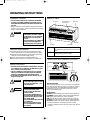
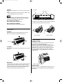
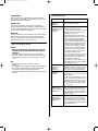
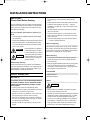
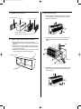
US STW PTAC
8/8/01 5:34 PM
Page 1
OWNER’S MANUAL
PACKAGED TERMINAL AIR CONDITIONER
Cool / Heat Model
STW-2 Series
Operating Instructions
Contents
Page
Alert Symbols ...........................................................
Installation Location ................................................
Electrical Requirements ..........................................
Safety Instructions ...................................................
Names of Parts .........................................................
Control Panel and Operation Functions ................
1
2
2
2
2
2
Front Grille ................................................................
Other Features..........................................................
Care and Cleaning....................................................
Tips for Energy Saving ............................................
Troubleshooting .......................................................
3
3
4
5
5
Installation Instructions
Contents
Model No.
Page
STW-2 Series
IMPORTANT!
Please Read Before Starting ................................... 6
1. NAMES OF PARTS............................................. 7
2. WALL CASE AND REAR GRILLE ..................... 7
3. INSTALLATION................................................... 7
4. PERMANENT CONNECTION............................. 8
4-1. For 230/208V Units ...................................... 8
4-1-1. Preparation ........................................ 8
4-1-2. Installation.......................................... 8
4-2. For 265V Units ............................................. 8
4-2-1. Preparation ........................................ 8
4-2-2. Installation.......................................... 8
5. AIR LOUVERS .................................................... 9
6. TEMPERATURE LIMITING................................. 9
7. REMOTE CONTROL ........................................ 10
8. FRONT DESK CONTROL ................................ 10
PRODUCT INFORMATION ............................... 11
85164119653000
© SANYO 2001
Power Source:
60 Hz, single-phase, 230/208V & 265V
Alert Symbols
The following symbols used in this manual alert you to potentially dangerous conditions to users, service personnel or the appliance:
WARNING
CAUTION
This symbol refers to a hazard or
unsafe practice which can result in
severe personal injury or death.
This symbol refers to a hazard or
unsafe practice which can result in
personal injury or product or property damage.
SANYO Electric Co., Ltd.
Osaka, Japan
W
W
US STW PTAC
8/8/01 5:34 PM
Page 2
OPERATING INSTRUCTIONS
Names of Parts
Installation Location
• We recommend that this air conditioner be installed
properly by qualified installation technicians in accordance with the Installation Instructions provided with
the unit.
• Before installation, check that the voltage of the electric
supply in your home or office is the same as the voltage
shown on the nameplate.
WARNING
Air outlet
• Do not install this air conditioner
where there are fumes or flammable gases, or in an extremely
humid space such as a greenhouse.
• Do not install the air conditioner
where excessively high heatgenerating devices are placed.
Cover switch and
control panel
Rear grille
Wall case
Air intake
Electrical Requirements
1. All wiring must conform to the local electrical codes.
Consult your dealer or a qualified electrician for details.
2. Each unit must be properly grounded with a ground (or
earth) wire or through the supply wiring.
3. Wiring must be done by a qualified electrician.
4. Never use an extention cord with this air conditioner.
Front grille
Air Intake
Air from the room is drawn into this section
and passes through air filters which remove
dust.
Air Outlet
Conditioned air is blown out of the air conditioner through the air outlet.
Control Panel and Operation Functions
Safety Instructions
• Read this Instruction Manual carefully before using this
air conditioner. If you still have any difficulties or problems, consult your dealer for help.
• This air conditioner is designed to give you comfortable room conditions. Use this only for its intended
purpose as described in this Instruction Manual.
• Avoid letting cooled/heated air blow directly on your
body for a long time.
WARNING
CAUTION
Thermostat
Mode
selector
Interamnegdeiate
r
72°F
• Never use or store gasoline or
other flammable vapor or liquid
near the air conditioner — it is
very dangerous.
(88°F)
WARMER
(55°F)
COOLER
Thermostat Control
The thermostat knob is used to control the room temperature. The unit automatically cycles on and off to maintain
room temperature. A comfortable temperature will be
maintained in most rooms when the control is set to
about intermediate range.
• Do not turn the air conditioner
on and off from the power
mains switch. Use the mode
selector switch.
• Do not stick anything into the
air outlet of the unit. This is dangerous because the fan is rotating at high speed.
• Do not let children play with the
air conditioner.
• Do not cool or heat the room
too much if babies or invalids
are present.
Mode Selector
HI HEAT provides heating with high fan speed operation.
LOW HEAT provides heating with low fan speed operation.
OFF setting stops heating or cooling operation.
FAN provides fan operation without cooling or heating.
LO COOL provides cooling with low fan speed operation.
HI COOL provides cooling with high fan speed operation.
∗ As long as power is connected to the unit, Freeze
Protection always functions at any position even at OFF
position.
2
US STW PTAC
8/8/01 5:34 PM
Page 3
Operation:
1. Set the mode selector for fan, cooling or heating operation.
2. Set the thermostat to the desired position. (Refer to the
Setting Temperature Guide on page 2.)
Front grille
Louver screws
NOTE
The temperatures at the Setting Temperature Guide on
Page 2 are provided for reference only, and may differ
from the actual temperature of the room.
How to stop the air conditioner:
Set the mode selector to OFF position.
The direction of the heated or cooled air may be adjusted
by removing and turning the louvers around.
How to restart the air conditioner:
Set the mode selector to the desired position.
Front Grille
To remove:
Additional controls are located behind the front grille.
Pull out to release it from the tabs. Then lift up.
37° OFF VERTICAL
20° OFF VERTICAL
2
Other Features
Front grille
Ventilation Control
The ventilation control lever is located at the upper left
side of the unit, behind the front grille.
This knob is set to CLOSE at the factory. When in this
position, the vent door is closed and only indoor air is circulated by the air conditioner. Switching the knob to
OPEN opens the vent door to allow outdoor air to enter
the room. However, leaving the vent door at OPEN
reduces heating or cooling effectiveness and increases
operating costs.
1
To reinstall:
Place the tabs over the top rail. Push inward until it snaps
into place.
1
2
Air Louvers
Ventilation control lever
To change the louver direction, remove the front grille and
2 louver screws that hold the louvers in place. Turn the
louver section 180° (end for end), replace the screws and
replace the front grille. The textured face of the louver
section must be facing toward the room side.
Remote Control
Remote controlling is available with the optional Class 2
Remote Controller and Interface kit. See the Installation
Instructions.
3
US STW PTAC
8/8/01 5:34 PM
Page 4
Care and Cleaning
Fan Cycle Switch
The Fan Cycle Switch is located under the control panel
behind the front grille. This switch is set to CONT at the
factory to provide continuous fan operation in cool or
heat modes. Leaving the switch at the CONT setting
allows continuous circulation of room air and will keep
the room temperature at stable condition. If you want the
fan to cycle on and off with the compressor or electrical
heater, set the switch to CYCLE.
THERMOSTAT
Turn off the air conditioner before cleaning.
Air Filters
The air filters should be cleaned at least once every two
weeks. Clogged filters reduce cooling, heating and air
flow.
Keeping these filters clean will:
• Decrease cost of operation.
• Save energy.
• Prevent clogged heat exchanger coils.
• Reduce costly compressor problems.
SELECTOR
To remove the air filters:
LOW OFF FAN
LOW
HEAT
COOL
HIGH
HIGH
HEAT
COOL
WARMER
COOLER
Pull up
Knob
2 air filters
Front
Control panel
THERMOSTAT
WARMER
To clean the air filters:
• Vacuum off heavy dirt.
• Run water through the filters.
• Dry thoroughly before replacing.
SELECTOR
LOW
HEAT
OFF
FAN
HIGH
HEAT
LOW
COOL
HIGH
COOL
COOLER
To reinstall the air filters:
CYCLE
Push
down
CONT
Fan cycle switch
Freeze Protection
Freeze Protection helps prevent plumbing damage due to
sub-freezing temperatures — even if you have turned the
mode selector switch to OFF. The unit automatically turns
on the heater and fan if the room temperature falls to
about 46°F.
NOTE
Do not operate the air conditioner without the filters in
place. If a filter becomes torn or damaged it should be
replaced immediately. Operating the unit without the filters in place or with damaged filters will allow dirt and
dust to reach the indoor coil and reduce the efficiency of
the unit.
You do not have to do anything to activate the Freeze
Protection. It will work as long as power to the unit has
not been interrupted.
Replacement filters (STK01AF) are available from the dealer or installer.
Front Grille & Wall Case
Wash the front grille and wall case finish with mild soap
or detergent and lukewarm water.
4
US STW PTAC
8/8/01 5:34 PM
Page 5
Troubleshooting
Control Panel
The control panel is shipped with a protective plastic
film. This film can be left on or removed. To clean, use a
damp cloth and mild detergent.
PROBLEM
Outdoor Coil
The coil on the outdoor side of the unit should be
checked periodically and cleaned if clogged with dirt or
soot from the atmosphere. If extremely dirty, it may need
to be professionally steam cleaned.
Base Pan
AIR CONDITIONER
DOES NOT
OPERATE
• The power cord is not plugged in or
circuit breaker is tripped.
AIR CONDITIONER
“DOES NOT COOL
OR HEAT AS IT
SHOULD”
• The unit is waiting for the compressor
overload protector to reset.
• Curtains, blinds or furniture blocking
the front of the air conditioner are
restricting the air flow.
• Thermostat control may not be set
high/low enough. Turn the control to a
lower or higher position. (NOTE: In
some installations, the thermostat
control cannot be turned all the way to
the highest end or lowest end. This is
normal. Do not attempt to force the
control beyond its stopping points.)
• A dirty air filter is blocking air flow.
The filter should be cleaned at least
once every 2 weeks. See the instructions in the cleaning section.
• The room may have been very hot or
very cold when the air conditioner
was first turned on. Allow time for it
to cool down or warm up.
• The ventilation control may be set to
the OPEN position, allowing outside
air to enter the room.
“BURNING” ODOR
AT START OF
HEATING
OPERATION
• Dust on the surface of the electrical
heater can cause a “burning” odor at
the beginning of the heating operation. This odor should quickly fade.
OPERATING
SOUNDS
• Relay clicks may be heard when the
compressor or fan cycles on and off.
This is normal.
• The fan runs continuously when the
unit is operating unless the Fan Cycle
Switch under the control panel is set
to CYCLE. In this case, the fan cycles
on and off with the electrical heater
or compressor.
AIR IS NOT
ALWAYS COOL
DURING COOLING
OPERATION
• The Fan Cycle Switch may be set to
Fan Cont (continuous). This causes
the fan to blow room air even when
the compressor is off. The continuous
air flow provides better overall temperature control.
AIR IS NOT
ALWAYS HOT
DURING HEATING
OPERATION
• The Fan Cycle Switch may be set to
Fan Cont (continuous). This causes
the fan to blow room air even when
the electrical heater is off. The continuous air flow provides better overall
temperature control.
In some installations, dirt or other foreign matter may be
blown into the unit from the outside and settle in the
base pan (the bottom of the unit). Check the base pan
periodically and clean it out, if necessary.
Tips for Energy Saving
Do not
• Block the air intake and outlet of the unit. If they are
obstructed, the unit will not work well, and may be
damaged.
• Let direct sunlight into the room. Use sunshades,
blinds or curtains. If the walls and ceiling of the room
are warmed by the sun, it will take longer to cool the
room.
Do
• Keep the air filter clean. (Refer to “Care and
Cleaning.”)
A clogged filter will impair the performance of the unit.
• To prevent conditioned air from escaping, keep windows, doors and any other openings closed.
• Keep the ventilator closed for economy and maximum
cooling.
5
POSSIBLE CAUSE
US STW PTAC
8/8/01 5:34 PM
Page 6
INSTALLATION INSTRUCTIONS
• DO NOT turn the air conditioner on and off by plugging
and unplugging. Use the Operation switch (SELECTOR).
• Follow National Electrical Code (NEC) and local codes,
ordinances and regulations. All wiring — including
installation of receptacles, must be in accordance with
these codes.
• The NEC requires permanent connection for installations over 250 volts.
• Protective devices (fuses or circuit breakers) acceptable for this air conditioner are specified on the nameplate of each unit.
• Aluminum building wiring may pose special problems
— consult a qualified electrician.
IMPORTANT!
Please Read Before Starting
This air conditioner meets strict safety and operating standards. As the installer or service person, it is an important
part of your job to install or service the system so it operates safely and efficiently.
For safe installation and trouble-free operation, you
must:
• Carefully read this OWNER’S MANUAL before installation and service.
• Follow each installation or service step exactly as shown.
• Observe all local, state, and national electrical codes.
When Transporting
• Pay close attention to all warning and caution notices
given in this manual.
WARNING
CAUTION
Be careful when picking up and moving the air conditioner.
Get a partner to help, and bend your knees when lifting to
reduce strain on your back. Sharp edges or thin aluminum
fins on the air conditioner can cut your fingers.
This symbol refers to a hazard or
unsafe practice which can result
in severe personal injury or death.
This symbol refers to a hazard or
unsafe practice which can result
in personal injury or product or
property damage.
When Servicing
• Turn the power OFF at the main power box (mains)
before opening the unit to check or repair electrical
parts and wiring.
• Keep your fingers and clothing away from any moving parts.
• Clean up the site after you finish, remembering to
check that no metal scraps or bits of wiring have been
left inside the unit being serviced.
If Necessary, Get Help
These instructions are all you need for most installation
sites and maintenance conditions. If you require help for a
special problem, contact our sales/service outlet or your
certified dealer for additional instructions.
Tools Needed
SPECIAL PRECAUTIONS
Phillips screwdriver
Flat blade screwdriver
When Wiring
Others
ELECTRICAL SHOCK CAN CAUSE SEVERE PERSONAL INJURY OR DEATH. ONLY A QUALIFIED, EXPERIENCED ELECTRICIAN SHOULD ATTEMPT TO WIRE
THIS SYSTEM.
CAUTION
• All wiring must conform to local electrical codes.
• Each unit must be properly grounded with a ground (or
earth) wire or through the supply wiring.
• DO NOT, under any circumstances, cut or remove the
third (ground) prong from the power cord plug.
• Never use an extension cord with this air conditioner.
• DO NOT use a damaged power cord, plug, or wall outlet. Replace them immediately.
• DO NOT change the internal wiring or any part of the
system.
• Before starting the installation, the power to the direct
connect wiring should be set to OFF.
• Ventilate any enclosed areas when installing or testing the
refrigeration system. Escaped refrigerant gas, on contact
with fire or heat, can produce dangerously toxic gas.
• Confirm upon completing installation that no refrigerant
gas is leaking. If escaped gas comes in contact with a
stove, gas water heater, electric room heater or other
heat source, it can produce dangerously toxic gas.
6
US STW PTAC
8/8/01 5:34 PM
Page 7
1. NAMES OF PARTS
Rear grille/louver**
Wall case**
3. INSTALLATION
Chassis
1) Remove the front grille by pulling out at the bottom to release it, then lift it up to clear the rail
along the chassis top.
Front grille*
2
1
* Shipped with the chassis
** Check essential components list on chassis
2) Slide the chassis into the wall case and secure
with four screws through the chassis flange
holes.
2. WALL CASE AND REAR GRILLE
1) The STK01WC wall case must be properly
installed according to the instructions packed with
the case.
2) Remove the corrugated stiffener and the outdoor
protective panel. Use the slit in the outdoor panel
as a grip and push out.
3) Install the rear grille from the room side according
to the instructions packed with the grille.
Protective panel
Wall
Slit
Wall case
3) Reinstall the front grille by hooking the top over
the rail along the chassis top, then pushing it in
at the bottom.
Stiffener
1
2
7
US STW PTAC
8/8/01 5:34 PM
Page 8
4. PERMANENT CONNECTION
Screw A
4-1. For 230/208V Units
Electrical
junction box
The 230/208V model is equipped for connection
with a power cord according to the unit capacity
at the time of shipment.
Power cord
Should local codes or special requirements specify permanent connection of this unit, use optional
adapter kit (Cover plate and Bottom plate)
STK02JB.
Screw B
Bottom plate
A power cord is supplied with 230/208V units. For
direct-connect applications, the power cord is cut
and a wire nut connection is made to the building
power supply. The cover plate and bottom plate
are the junction box kit. The conduit and wire
nuts are supplied by the installer.
Conduit
Cover plate
4-1-1. Preparation
4-2. For 265V Units
1) The electrical rating marked on the previously
installed air conditioner must be the same as the
supply branch circuit.
All 265V units are direct connected and come
with the cover plate (junction box) and bottom
plate. The conduit is field-supplied by the
installer.
2) The modification kit provides for connection of
1/2" trade size electrical conduit and connection to
a wiring system in accordance with the National
Electric Code, ANSI/NFPA No. 70-1999.
4-2-1. Preparation
1) The electrical rating marked on the previously
installed air conditioner must be the same as the
supply branch circuit.
4-1-2. Installation
1) Remove the Front Grille from the chassis by lifting out and up.
2) The unit provides for connection of 1/2 trade size
electrical conduit and provision for connection to
a wiring system in accordance with the National
Electrical Code ANSI/NFPA No. 70-1993.
2) Cut the power cord approximately 6" from the
Electrical Junction Box.
4-2-2. Installation
Cut
1) Remove the front grille from the chassis by lifting
out and up to clear mounting brackets. (See “Front
Grille” on page 3.)
Approx. 6"
2) Remove the “A” screw and cover plate from the
mounting plate.
Power plug
Electrical junction box
Screw A
3) Split and strip the wires as shown above.
4) Install the Bottom Plate using the provided field
supplied conduit and power supply conductors to
the unit with screw “B”.
Screws
5) Connect Power Supply wires to the stripped inner
wires with the wire nuts.
6) Dress the wiring inside the compartment and
attach the cover plate with screw “A”.
7) Reinstall the Front Grille.
Cover plate
Bottom plate
8
US STW PTAC
8/8/01 5:34 PM
Page 9
3) Attach the field-supplied conduit to the
bottom plate.
4) Connect the power supply conductors to
the Terminal block and the Grounding
screw.
5) Attach the cover plate.
6. TEMPERATURE LIMITING
The normal range of the thermostat control is
approximately 55°F to 88°F. The control range may
be narrowed by the use of the Temperature Limiting
screws located behind the control panel.
Repositioning the screw on the left will limit the
maximum temperature about 3.7°F for each hole in
a clockwise rotation; the screw on the right will limit
the minimum temperature when moved counterclockwise. Limiting the maximum and minimum settings prevents users from turning the controls to
extreme positions. Restrictions to full rotation of the
thermostat knob may require explanation to the
room occupant that the unit will provide comfortable conditions at the settings allowed.
Terminal block
Grounding screw
Cover plate
Bottom plate
To access the limiting screws, remove the front
grille, the thermostat knob and the operation knob
by pulling each knob off its shaft and the control
panel. (See the illustration “Fan Cycle Switch” on
page 4.) Set the limiting screws to the desired setting, and replace the control panel and the control
knobs. If the settings do not allow sufficient room
temperature control, the limiting screws may have
to be repositioned.
Conduit
6) Reinstall the front grille. (See “Front
Grille” on page 3.)
Stop link
Tapped holes (10)
5. AIR LOUVERS
The direction of the heated or cooled air may be
adjusted by removing and turning the louvers
around.
Thermostat
shaft
(Warmest)
(Coldest)
Temperature limiting screws (location at shipment)
When the limiting screws are relocated, it is recommended that the screws be set no higher than the
second hole from the original bottom position. This
provides an operating range between approximately
58°F and 80°F. In order to maximize the benefit of the
temperature limiting, it may be necessary to adjust
the limiting screws seasonally, maintained at moderate temperatures (i.e., heating season temperatures
limited between 60°F and 75°F; cooling season temperatures limited between 85°F and 65°F).
To change the louver direction, remove the front
grille and 2 louver screws that hold the louvers in
place. Turn the louver section 180° (end for end),
replace the screws and replace the front grille. The
textured face of the louver section must be facing
toward the room side.
Front grille
Louver screws
9
US STW PTAC
8/8/01 5:34 PM
Page 10
Remote Control
7. REMOTE CONTROL
8. FRONT DESK CONTROL
The unit may be controlled either by the unit-mounted controls (Control Panel) or by optional Class 2 thermo controller (SC2001 for Cool/Heat Model and
SC2201 for Heat Pump Model) with optional Interface
kit (STK02LVC). Detailed instructions are included in
the kit.
FDC
The unit may be connected to a switch at the front
desk to control on and off operation of the compressor or heater from the front desk with the optional
interface kit. (See the picture below.) When the switch
is set to OPEN, the unit is operable. When the switch
is set to CLOSED, the unit is made inoperative.
Detailed hook-up instructions are in the interface kit.
Follow the recommended wire sizing in the table
below. Two wires must be used from each FDC switch
to each individual unit.
Class 2 Remote
Good wiring practices (e.g. twisted pairs, SEPARATION FROM POWER CIRCUITS) must be followed to
minimize induced voltages which may harm the control system. Do not use a common line in the FDC
wiring.
Low voltage
Terminals on Interface kit
A 24V A/C transformer is contained within the unit
and no external voltage should be applied to the unit
through the FDC switch. The Freeze Protection
remains in active mode to help protect against low
temperature damage even though the unit may be
OFF by FDC.
Recommended Wire Size for Front Desk Control
Installation
Wire Size #AWG
#22
#20
#18
#16
Interface kit
(optional)
Terminals
10
Maximum Allowable Length
600 ft.
900 ft.
1500 ft.
2000 ft.
US STW PTAC
8/8/01 5:34 PM
Page 11
Product Information
If you have problems or questions concerning your Air Conditioner, you will need the following information.
Model and serial numbers are on the nameplate of the cabinet.
Model No.
Serial No.
Date of purchase
Dealer’s address
Phone number
11
US STW PTAC
8/8/01 5:34 PM
Page 12
SANYO FISHER COMPANY
In Canada
A DIVISION OF SANYO NORTH AMERICA CORPORATION
21605 plummer Street, Chatsworth, CA 91311 U.S.A.
SANYO Canada Inc.
300 Applewood Crescent, Concord, Ontario, L4K 5C7, Canada