1
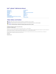
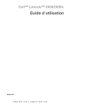
FCC Class B Test Report
For A Class B Digital Device
Client:
SanDisk Corporation
7 Atir Yeda Street
Kfar Saba, Israel
Phone 972-9-7644908
Device Under Test:
SanDisk SSD SATA 5000 2.5”
Document Number: 2007160
Reference Number: QRTL07-033
This report may not be reproduced, except in full, without the written approval of Rhein Tech Laboratories, Inc.
Test Overview:
Model No.:
Manufacturer’s
Name:
Manufacturer’s
Address:
Manufacturer’s
Contact:
Type of Equipment:
Serial No.:
Year of Manufacture:
Location of Testing:
Date of Receipt:
Date(s) of Testing:
Purpose of Testing:
SanDisk SSD SATA 5000 2.5”
SanDisk Corporation
7 Atir Yeda Street
Kfar Saba, Israel
Eitan Chalfon
ITE
713050010
2007
Rhein Tech Laboratories, Inc., Herndon, VA
February 5, 2007
April 10, 2007
FCC Class B Compliance
Standard(s) to which device was tested:
STANDARDS
CFR47 Parts 15.109 and
15.107
SPECIFIC TESTS
APPLICABILITY
Tested
Not Tested
Radiated and Conducted Emissions
Test Engineer:
Jon Wilson
Signature:
Report Written By:
Jon Wilson
Signature:
Report Approved By:
Desmond Fraser
Signature:
Report Number:
Report Date:
2007160
April 27, 2007
®
Accredited by the National Voluntary Accreditation Program for the specific scope of accreditation under
Lab Code 20061-0.
Note: This report may not be used by the client to claim product endorsement by NVLAP or any agency of the U.S. Government.
360 Herndon Parkway
Suite 1400
Herndon, VA 20170
http://www.rheintech.com
TABLE OF CONTENTS
1
GENERAL INFORMATION ............................................................................................................................. 4
1.1
1.2
2
TEST DETAILS................................................................................................................................................ 5
2.1
2.2
2.3
2.4
2.5
3
DOC LABEL ON DEVICE............................................................................................................................... 8
DOC STATEMENT IN USER’S MANUAL........................................................................................................... 8
LOCATION OF LABEL ON EUT....................................................................................................................... 8
CONDUCTED EMISSIONS ............................................................................................................................. 9
4.1
4.2
4.3
5
PRODUCT DESCRIPTION .............................................................................................................................. 5
MODIFICATIONS........................................................................................................................................... 5
EUT EXERCISE DESCRIPTION ...................................................................................................................... 5
EQUIPMENT UNDER TEST ............................................................................................................................ 6
CONFIGURATION OF TESTED SYSTEM........................................................................................................... 7
PRODUCT LABELLING/ INFORMATION TO THE USER............................................................................. 8
3.1
3.2
3.3
4
DEVIATIONS ................................................................................................................................................ 4
ACCREDITATION STATEMENTS ..................................................................................................................... 4
SITE AND TEST DESCRIPTION....................................................................................................................... 9
CONDUCTED EMISSIONS TEST DATA .......................................................................................................... 10
CONDUCTED TEST PHOTOGRAPHS............................................................................................................. 11
RADIATED EMISSIONS................................................................................................................................ 12
5.1
5.2
5.3
5.4
SITE AND TEST DESCRIPTION..................................................................................................................... 12
FIELD STRENGTH CALCULATION ................................................................................................................. 13
RADIATED EMISSIONS TEST DATA .............................................................................................................. 14
RADIATED TEST PHOTOGRAPHS ................................................................................................................ 15
6
EMISSIONS EQUIPMENT LIST .................................................................................................................... 16
7
MANUFACTURER’S EQUIPMENT FILE CHECKLIST (PER FCC RULES §2.1075).................................. 17
SanDisk Corporation
DoC Report
2006137
04/27/07
Page 3 of 17
360 Herndon Parkway
Suite 1400
Herndon, VA 20170
http://www.rheintech.com
1
GENERAL INFORMATION
The following test report for a Class B digital device is prepared on behalf of SanDisk Corporation in
accordance with Part 2, and Part 15, Subparts A and B of the Federal Communications Commissions Rules and
Regulations. The Equipment Under Test (EUT) was the SanDisk SSD SATA 5000 2.5”. The test results
reported in this document relate only to the items that were tested.
All measurements contained in this Application were conducted in accordance with ANSI C63.4 Methods of
Measurement of Radio Noise Emissions, 2003. The instrumentation utilized for the measurements conforms to
the ANSI C63.4 standard for EMI and Field Strength Instrumentation. Some accessories are used to increase
sensitivity and prevent overloading of the measuring instrument. Calibration checks are performed regularly on
all test equipment.
All radiated and conducted emission measurements were performed manually at Rhein Tech Laboratories, Inc.
The radiated emissions measurements were performed on the (three/ten) meter, open field, test range
maintained by Rhein Tech Laboratories, Inc., 360 Herndon Parkway, Suite 1400, Herndon, Va., 20170.
Complete description and site attenuation measurement data has been placed on file with the Federal
Communications Commission. The power line conducted emission measurements were performed in a
shielded enclosure also located at the Herndon, Virginia facility. Rhein Tech Laboratories is accepted by the
FCC as a facility available to do measurement work for others on a contract basis.
1.1
DEVIATIONS
There were no deviations from the test standard(s) and/or methods.
1.2
ACCREDITATION STATEMENTS
•
NVLAP (USA): Accreditation under NVLAP Lab Code: 200061-0
•
US CAB: Recognition as of U.S. Conformity Assessment Body (CAB) for EMC testing under US-EU and
US-APEC MRA; IC accepted CAB under Phase I of APEC Telecommunication MRA. Identification
number US0079.
•
FCC (USA): Listing of test sites, Registration # 90902
•
IC (Canada): Listing of test sites, IC 2956-1 and IC 2956-2
•
US TCB (ATCB): Certification of cooperation, granted in 2005
•
CE Notified Body: Rhein Tech Laboratories, Inc. has been approved by TNO Certification B.V. to provide
EMC Test Reports and Technical Construction Files to TNO Certification B.V. Rheintech Certification
number: 10118957
•
AUSTEL (Australia): Acceptance as of a Listed Test House, A97/TH/0107
•
ANATEL (Brazil, telecommunication): NCC certification for performing tests
•
Ministry of Commerce (New Zealand): Approval of a test laboratory: ECR 3-9 BAE
•
VCCI (Japan): Approval and registration of RTL test sites as R-1113 and C-1172
SanDisk Corporation
DoC Report
2006137
04/27/07
Page 4 of 17
360 Herndon Parkway
Suite 1400
Herndon, VA 20170
http://www.rheintech.com
2
TEST DETAILS
2.1
PRODUCT DESCRIPTION
SanDisk SATA 5000 2.5” SSD is a drop-in replacement for the hard disk drive. It has no moving/ mechanical
parts.
Features
o 2.5" small form factor supporting unformatted capacity of 32GB
o 9.5mm case height
o SATA 7+15 pins combo connector
Interface to host
o Standards: SATA 1.0a 1.5Gb/s
High performance
o Host transfer rate: 150MB/s
o Internal transfer read rate: 67MB/s
o Internal transfer write rate: 47MB/s
o Random Read (4KB): 5350 IOPS
o Average access time: 0.11msec
Low power consumption
o Supply voltage: 5Vdc
o Typical read/write: 190mA
o Typical idle: 125mA
o Typical standby: 70mA
o Typical sleep: 60mA
Reliability
o Mean time between failure (MTBF): 2,000,000 hours, based on Part Stress Analysis
o Operating shock: 1,500G, 0.5msec half sine
o Operating vibration: 2.17G, 7-500 Hz
o Operating temperature: 0˚C to 70˚C
o Non operating temperature and storage: -55˚C to 95˚C
o Operating temperature: 0˚C to 70˚C
2.2
MODIFICATIONS
None
2.3
EUT EXERCISE DESCRIPTION
The SanDisk SSD SATA 5000 2.5” was installed in a Class B laptop personal computer which was running
Windows XP. The computer was programmed to transfer files continuously, to and from the device under test
using a software application provided by Dell. The SanDisk SSD SATA 5000 2.5” was tested as a
representative of the full line of available capacities. The only difference among the different sizes is the onboard flash memory. Otherwise, there are no physical, clock, or electronic changes. Determination of the 2.5
as the “worst case” test sample was determined by SanDisk based on preliminary scanning of the devices under
test and engineering judgement that: because of the small changes between the various capacities, any
changes in emission amplitudes or EMC susceptibility would be inconsequential.
SanDisk Corporation
DoC Report
2006137
04/27/07
Page 5 of 17
360 Herndon Parkway
Suite 1400
Herndon, VA 20170
http://www.rheintech.com
2.4
EQUIPMENT UNDER TEST
Listed below are the identifiers and descriptions of all equipment, cables, and internal devices used with the EUT for this test.
Equipment Under Test
Part
SATA Storage
Device
Manufacturer
SanDisk
Corporation
Model
SanDisk SSD
SATA 5000 2.5”
Serial
Number
713050010
FCC
ID
DoC
Cable
Description
Internal
RTL
Bar
Code
N/A
Equipment
Arrival
Date
4/10/2007
Auxiliary Equipment
Part
Laptop PC
Manufacturer
Dell
Model
Serial
Number
FCC
ID
Cable
Description
RTL
Bar
Code
Equipment
Arrival
Date
Latitude D620
PP18L
N/A
DoC
Unshielded
Power
N/A
4/10/2007
N/A
Unshielded
017737
4/10/2007
901427
12/15/2005
011966
008645
011726
016989
09/22/1999
04/07/1997
05/09/1996
01/24/2006
Laptop AC Adapter
Dell
LA65NS0-00
CN-0DF263716156822ED4
Monitor
Mag Innovision
LT716s 700P
F6EQ581028
18U
DoC
Speaker
USB Termination
USB Termination
Microphone
Boston Acoustics
Gateway, Inc.
Gateway, Inc.
Gateway, Inc.
BA265
USB PCB
USB PCB
Telex
7002305
Rev 1.0
Rev 1.0
700358
N/A
N/A
N/A
N/A
Unshielded
Power
Shielded I/O
Unshielded
Shielded
Shielded
Unshielded
Ethernet hub
Flowpoint
134
F258219
Class
A
Device
Unshielded
Power
901278
10/04/2002
Modem
US Robotics
Sportster Model
0413
8390364644
992
DoC
Unshielded
Power
Shielded I/O
900427
11/13/1996
SanDisk Corporation
DoC Report
2006137
04/27/07
Page 6 of 17
360 Herndon Parkway
Suite 1400
Herndon, VA 20170
http://www.rheintech.com
2.5
CONFIGURATION OF TESTED SYSTEM
Modem
Speaker
SanDisk Corporation
DoC Report
2006137
04/27/07
Microphone
Laptop PC with
SanDisk SSD
SATA 5000
USB
Termination
Monitor
Page 7 of 17
360 Herndon Parkway
Suite 1400
Herndon, VA 20170
http://www.rheintech.com
3
3.1
PRODUCT LABELLING/ INFORMATION TO THE USER
DOC LABEL ON DEVICE
The label shall be located in a conspicuous location on the device and shall contain the unique
identification described in FCC CFR 47; Section 2.1074 (the unique model name), and the
following DoC logo:
SanDisk Corporation
3.2
SanDisk SSD SATA 5000 2.5”
DOC STATEMENT IN USER’S MANUAL
For a Class B digital device or peripheral, per FCC CFR 47; Section 15.105, the instructions
furnished the user shall include the following or similar statement, placed in a prominent location
in the text of the manual:
NOTE: This equipment has been tested and found to comply with the limits for a Class B digital device,
pursuant to part 15 of the FCC Rules. These limits are designed to provide reasonable protection against
harmful interference in a residential installation. This equipment generates, uses and can radiate radio
frequency energy and, if not installed and used in accordance with the instructions, may cause harmful
interference to radio communications. However, there is no guarantee that interference will not occur in a
particular installation. If this equipment does cause harmful interference to radio or television reception,
which can be determined by turning the equipment off and on, the user is encouraged to try to correct
the interference by one or more of the following measures:
—Reorient or relocate the receiving antenna.
—Increase the separation between the equipment and receiver.
—Connect the equipment into an outlet on a circuit different from that to which the receiver
is connected.
—Consult the dealer or an experienced radio/ TV technician for help.
3.3
LOCATION OF LABEL ON EUT
Label
Location
SanDisk Corporation
DoC Report
2006137
04/27/07
Page 8 of 17
360 Herndon Parkway
Suite 1400
Herndon, VA 20170
http://www.rheintech.com
4
4.1
CONDUCTED EMISSIONS
SITE AND TEST DESCRIPTION
The power line conducted emission measurements were performed in a Series 81 type shielded enclosure
manufactured by Rayproof. The EUT was assembled on a wooden table 80 centimeters high. Power was fed to
the EUT through a 50 ohm /50 microhenry Line Impedance Stabilization Network (EUT LISN). The EUT LISN
was fed power through an A.C. filter box on the outside of the shielded enclosure. The filter box and EUT LISN
housing are bonded to the ground plane of the shielded enclosure. A second LISN, the peripheral LISN,
provides isolation for the EUT test peripherals. This peripheral LISN was also fed A.C. power. A metal power
outlet box, which is bonded to the ground plane and electrically connected to the peripheral LISN, powers the
EUT host peripherals.
The spectrum analyzer was connected to the A.C. line through an isolation transformer. The 50-ohm output of
the EUT LISN was connected to the spectrum analyzer input through a Solar 7 kHz high-pass filter. The filter is
used to prevent overload of the spectrum analyzer from noise below 7 kHz. Conducted emission levels were
measured on each current-carrying line with the spectrum analyzer operating in the CISPR quasi-peak mode (or
average mode if applicable). The analyzer's 6 dB bandwidth was set to 9 kHz. No video filter less than 10 times
the resolution bandwidth was used. Average measurements are performed in linear mode using a 10 kHz
resolution bandwidth, a 1 Hz video bandwidth, and by increasing the sweep time in order to obtain a calibrated
measurement. The range of the frequency spectrum to be investigated is specified in FCC Part 15. The highest
emission amplitudes relative to the appropriate limit were measured and have been recorded in this report.
SanDisk Corporation
DoC Report
2006137
04/27/07
Page 9 of 17
360 Herndon Parkway
Suite 1400
Herndon, VA 20170
http://www.rheintech.com
4.2
CONDUCTED EMISSIONS TEST DATA
Mode: 115 vac, 60 Hz.
Neutral Conductor
Emission
Frequency
(MHz)
Test
Detector
Analyzer
Reading
(dBuV)
0.157
0.157
0.186
0.186
0.212
0.221
0.265
0.320
0.320
0.372
0.372
0.710
1.650
4.450
15.070
17.640
25.100
Qp
Av
Qp
Av
Qp
Qp
Qp
Qp
Av
Qp
Av
Pk
Pk
Pk
Pk
Pk
Pk
56.2
33.4
54.7
21.8
42.4
43.7
46.6
54.0
29.3
51.7
30.9
40.4
35.5
35.6
25.2
28.2
29.4
Emission
Frequency
(MHz)
Test
Detector
Analyzer
Reading
(dBuV)
0.155
0.155
0.186
0.186
0.213
0.213
0.265
0.294
0.377
0.423
0.500
2.740
9.910
18.640
25.070
28.850
Qp
Av
Qp
Av
Qp
Av
Qp
Qp
Qp
Qp
Pk
Pk
Pk
Pk
Pk
Pk
58.5
34.7
54.5
20.8
52.2
38.1
46.6
41.0
39.8
39.6
38.5
31.2
24.0
28.0
29.8
22.2
Temperature: 75°F Humidity: 31%
Site
Emission CISPR B CISPR B
Correction
Level
QP
QP
Factor
(dBuV)
Limit
Margin
(dB)
(dBuV)
(dBuV)
0.2
56.4
65.6
-9.2
0.2
33.6
65.6
-32.0
0.2
54.9
64.2
-9.3
0.2
22.0
64.2
-42.2
0.2
42.6
63.1
-20.5
0.2
43.9
62.8
-18.9
0.2
46.8
61.3
-14.5
0.3
54.3
59.7
-5.4
0.3
29.6
59.7
-30.1
0.3
52.0
58.5
-6.5
0.3
31.2
58.5
-27.3
0.2
40.6
56.0
-15.4
0.7
36.2
56.0
-19.8
1.3
36.9
56.0
-19.1
2.3
27.5
60.0
-32.5
2.5
30.7
60.0
-29.3
2.7
32.1
60.0
-27.9
CISPR B
AV
Limit
(dBuV)
55.6
55.6
54.2
54.2
53.1
52.8
51.3
49.7
49.7
48.5
48.5
46.0
46.0
46.0
50.0
50.0
50.0
CISPR B
AV
Margin
(dBuV)
Temperature: 75°F Humidity: 31%
Site
Emission CISPR B CISPR B
Correction
Level
QP
QP
Factor
(dBuV)
Limit
Margin
(dB)
(dBuV)
(dBuV)
0.2
58.7
65.7
-7.0
0.2
34.9
65.6
-30.7
0.2
54.7
64.2
-9.5
0.2
21.0
64.2
-43.2
0.2
52.4
62.7
-10.3
0.2
38.3
63.1
-24.8
0.2
46.8
61.3
-14.5
0.3
41.3
60.4
-19.1
0.3
40.1
58.3
-18.2
0.2
39.8
57.4
-17.6
0.2
38.7
56.0
-17.3
1.0
32.2
56.0
-23.8
1.9
25.9
60.0
-34.1
2.6
30.6
60.0
-29.4
2.7
32.5
60.0
-27.5
3.1
25.3
60.0
-34.7
CISPR B
AV
Limit
(dBuV)
55.7
55.6
54.2
54.2
52.7
53.1
51.3
50.4
48.3
47.4
46.0
46.0
50.0
50.0
50.0
50.0
CISPR B
AV
Margin
(dBuV)
Pass/
Fail
Pass
Pass
Pass
Pass
Pass
Pass
Pass
Pass
Pass
Pass
Pass
Pass
Pass
Pass
Pass
Pass
Pass
-22.0
-32.2
-10.5
-8.9
-4.5
-20.1
-17.3
-5.4
-9.8
-9.1
-22.5
-19.3
-17.9
Phase Conductor
-20.7
-33.2
-14.8
-4.5
-9.1
-8.2
-7.6
-7.3
-13.8
-24.1
-19.4
-17.5
-24.7
Pass/
Fail
Pass
Pass
Pass
Pass
Pass
Pass
Pass
Pass
Pass
Pass
Pass
Pass
Pass
Pass
Pass
Pass
Result: PASS
Test Personnel:
Jon Wilson
Tester
SanDisk Corporation
DoC Report
2006137
04/27/07
Signature
April 10, 2007
Date of Test
Page 10 of 17
360 Herndon Parkway
Suite 1400
Herndon, VA 20170
http://www.rheintech.com
4.3
CONDUCTED TEST PHOTOGRAPHS
SanDisk Corporation
DoC Report
2006137
04/27/07
Page 11 of 17
360 Herndon Parkway
Suite 1400
Herndon, VA 20170
http://www.rheintech.com
5
5.1
RADIATED EMISSIONS
SITE AND TEST DESCRIPTION
Before final measurements of radiated emissions were made on the open-field three/ten meter range,
the EUT was scanned indoor at one and three meter distances. This was done in order to determine
its emissions spectrum signature. The physical arrangement of the test system and associated
cabling was varied in order to determine the effect on the EUT's emissions in amplitude, direction and
frequency. This process was repeated during final radiated emissions measurements on the openfield range, at each frequency, in order to insure that maximum emission amplitudes were attained.
Final radiated emissions measurements were made on the three/ten-meter, open-field test site. The
EUT was placed on a nonconductive turntable 0.8 meter above the ground plane. The spectrum was
examined as per FCC part 15 specifications.
At each frequency, the EUT was rotated 360°, and the antenna was raised and lowered from 1 to 4
meters in order to determine the emission’s maximum level. Measurements were taken using both
horizontal and vertical antenna polarizations. For frequencies between 30 and 1000 MHz, the
spectrum analyzer’s 6 dB bandwidth was set to 120 kHz, and the analyzer was operated in the CISPR
quasi-peak detection mode. For emissions above 1000 MHz, measurement use an average detector
function with a minimum resolution bandwidth of 1 MHz. No video filter less than 10 times the
resolution bandwidth was used. The highest emission amplitudes relative to the appropriate limit
were measured and recorded in this report.
Rhein Tech Laboratories, Inc. has implemented procedures to minimize errors that occur from test
instruments, calibration, procedures, and test setups. Test instrument and calibration errors are
documented from the manufacturer or calibration lab. Other errors have been defined and calculated
within the Rhein Tech quality manual, section 6.1. Rhein Tech implements the following procedures to
minimize errors that may occur: yearly as well as daily calibration methods, technician training, and
emphasis to employees on avoiding error.
SanDisk Corporation
DoC Report
2006137
04/27/07
Page 12 of 17
360 Herndon Parkway
Suite 1400
Herndon, VA 20170
http://www.rheintech.com
5.2
FIELD STRENGTH CALCULATION
The field strength is calculated by adding the Antenna Factor and Cable Factor, and subtracting the
Amplifier Gain (if any) from the measured reading. The basic equation with a sample calculation is as
follows:
FI(dBuV/m) = SAR(dBuV) + SCF(dB/m)
FI = Field Intensity
SAR = Spectrum Analyzer Reading
SCF = Site Correction Factor
The Site Correction Factor (SCF) used in the above equation is determined empirically, and is
expressed in the following equation:
SCF(dB/m) = - PG(dB) + AF(dB/m) + CL(dB)
SCF = Site Correction Factor
PG = Pre-amplifier Gain
AF = Antenna Factor
CL = Cable Loss
The field intensity in microvolts per meter can then be determined according to the following equation:
FI(dBuV/m)/20
FI(uV/m) = 10
For example, assume a signal at a frequency of 125 MHz has a received level measured as 49.3
dBuV. The total Site Correction Factor (antenna factor plus cable loss minus preamplifier gain) for
125 MHz is -11.5 dB/m. The actual radiated field strength is calculated as follows:
49.3 dBuV - 11.5 dB/m = 37.8 dBuV/m
37.8/20
10
SanDisk Corporation
DoC Report
2006137
04/27/07
1.89
= 10
= 77.6 uV/m
Page 13 of 17
360 Herndon Parkway
Suite 1400
Herndon, VA 20170
http://www.rheintech.com
5.3
RADIATED EMISSIONS TEST DATA
Emission
Frequency
(MHz)
Test
Detector
Antenna
Polarity
(H/V)
50.000
73.800
144.000
191.992
200.000
225.000
250.000
369.340
406.340
463.850
485.970
631.945
700.000
Qp
Qp
Qp
Qp
Qp
Qp
Qp
Qp
Qp
Qp
Qp
Qp
Qp
H
V
V
V
V
V
H
H
V
H
V
V
V
Temperature: 48°F
Humidity: 36%
Turntable Antenna Analyzer
Site
Emission
Azimuth
Height
Reading Correction
Level
(deg)
(m)
(dBuV)
Factor
(dBuV/m)
(dB/m)
200
3.0
38.4
-22.2
16.2
100
1.0
41.6
-23.5
18.1
5
1.0
40.1
-18.5
21.6
80
1.0
42.2
-19.4
22.8
190
1.0
35.3
-19.0
16.3
290
1.0
32.7
-18.5
14.2
160
4.0
44.2
-15.5
28.7
190
1.5
42.8
-12.1
30.7
270
1.0
32.9
-10.5
22.4
75
2.5
38.8
-9.5
29.3
190
1.0
29.4
-8.9
20.5
45
1.0
30.8
-6.2
24.6
5
1.0
30.4
-5.8
24.6
Limit
(dBuV/m)
Margin
(dB)
30.0
30.0
30.0
30.0
30.0
30.0
37.0
37.0
37.0
37.0
37.0
37.0
37.0
-13.8
-11.9
-8.4
-7.2
-13.7
-15.8
-8.3
-6.3
-14.6
-7.7
-16.5
-12.4
-12.4
Pass/
Fail
Pass
Pass
Pass
Pass
Pass
Pass
Pass
Pass
Pass
Pass
Pass
Pass
Pass
Note:
The EUT was scanned from 30 MHz to 15,000 MHz. All emissions other than those listed in the tables above were found to
have amplitudes attenuated by more than 20dB below the FCC limit.
Result: Pass
Test Personnel:
Jon Wilson
EMC Test Engineer
SanDisk Corporation
DoC Report
2006137
04/27/07
Signature
April 10, 2007
Date Of Test
Page 14 of 17
360 Herndon Parkway
Suite 1400
Herndon, VA 20170
http://www.rheintech.com
5.4
RADIATED TEST PHOTOGRAPHS
SanDisk Corporation
DoC Report
2006137
04/27/07
Page 15 of 17
360 Herndon Parkway
Suite 1400
Herndon, VA 20170
http://www.rheintech.com
6
EMISSIONS EQUIPMENT LIST
The following is a list of equipment Rhein Tech uses to perform testing.
Part Type
Spectrum Analyzer (10kHz-1.5GHz)
Spectrum Analyzer Display Section
Quasi-Peak Adapter
Filter
16A LISN
16A LISN
Current Probe (Telecom conducted)
Emissions testing software
EMI Receiver RF Section, 9 KHz - 6.5 GHz
RF Filter Section, 100 KHz to 6.5 GHz
Amplifier
Bi-Log Antenna (20MHz-2GHz)
Emissions testing software
SanDisk Corporation
DoC Report
2006137
04/27/07
Manufacturer
Model
Conducted Emissions (SR2, SA3)
Hewlett Packard
8567A
Hewlett Packard
85662A
Hewlett Packard
85650A
Solar
8130
AFJ International
LS16/110VAC
AFJ International
LS16/110VAC
Fischer Custom Communications
F-14-1
Rhein Tech Laboratories, Inc.
Automated Emission Tester
Radiated Emissions
Hewlett Packard
85462A
Hewlett Packard
85460A
RTL
PR-1040
Schaffner Chase
CBL6112B
Rhein Tech Laboratories, Inc.
Automated Emission Tester
Serial Number
Barcode
Cal Due Date
2602A00160
2542A11239
2521A00743
947306
16010020080
16010020081
33
Rev. 14.0.2
900968
900970
900339
900729
901083
901082
901084
N/A
8/14/2007
8/14/2007
8/14/2007
N/A
4/4/2008
1/6/2008
8/31/2007
N/A
3325A00159
3330A00107
1004
2648
Rev. 14.0.2
900913
900914
901281
901053
N/A
3/21/2008
3/21/2008
1/19/2008
11/1/2007
N/A
Page 16 of 17
360 Herndon Parkway
Suite 1400
Herndon, VA 20170
http://www.rheintech.com
7
MANUFACTURER’S EQUIPMENT FILE CHECKLIST (PER FCC RULES §2.1075)
This checklist shall be used by the manufacturer to verify the correct filing per FCC 2.1075 Retention of records
for products produced and marketed.
PRODUCT MODEL(s):
Records Verified By:
SanDisk SSD SATA 5000 2.5”
A record of the original design drawings and specifications.
A record of all changes that have been made that would affect continued compliance
with the authorized unit (e.g., any changes which would require a Class I or Class II
permissive change).
A record of the procedures used for production inspection and testing (if tests were
performed) to ensure ongoing conformance.
A record of the measurements made on an appropriate (NVLAP-accredited) test site
that demonstrates compliance. The record shall contain:
• (i) The actual date or dates testing was performed;
• (ii) The name of the test laboratory, or individual performing the testing. (The
Commission may request additional information regarding the test site, the test
equipment or the qualifications of the Test laboratory from the client. or individual
performing the tests);
• (iii) A description of how the device was actually tested, identifying the measurement
procedure and test equipment that was used contained in the test report
• (iv) A description of the equipment under test (EUT) and support equipment
connected to, or installed within the EUT
• (v) The identification of the EUT and support equipment by trade name and model
number and, if appropriate, by FCC identifier and serial number;
• (vi) The types and lengths of connecting cables used and how they were arranged
or moved during testing;
• (vii) At least two photographs showing the test set-up for the highest line conducted
emission and showing the test set-up for the highest radiated emission. These
photographs must be focused originals which show enough detail to confirm other
information contained in the test report;
• (viii) A description of any modifications made to the EUT Client, or individual to
achieve compliance with the regulations;
• (ix) All of the data required to show compliance with the appropriate regulations;
• (x) The signature of the individual responsible for testing the product along with the
name and signature of an official of the responsible party, as designated in §2.909;
• (xi) A copy of the compliance information (i.e., the DoC), as described in §2.1077,
required to be provided with the equipment as follows:
(a) Identification of the product (name and model number);
(b) The unique model name and FCC DoC logo information as specified in
§15.19(b)(1) and §15.105, that the product complies with Part 15 of the FCC
Rules;
(c) Identification, by name, and address of the responsible party.
SanDisk Corporation
DoC Report
2006137
04/27/07
Page 17 of 17