1
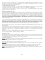
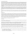
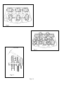
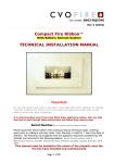
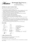
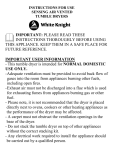
0102 095 50023
CLASS 2 – FLAME SYSTEM 3
USERS (Pages 2-3)/ INSTALLATION (Pages 4-9)
AND SERVICING INSTRUCTIONS
THIS CAT I2H APPLIANCE IS FOR USE
ON NATURAL GAS G20 AT A SUPPLY
PRESSURE OF 20 mbar IN GB and IE
HAND THESE INSTRUCTIONS TO THE USER
USERS INSTRUCTIONS
Description
This Royal Cozy Fires Decorative Fuel Effect gas fire has been developed to give a realistic coal burning appearance with
the instant control and convenience of gas. The fire has been constructed to enable it to be installed into most applications
(using the optional spacer frame) where the warmth and comfort of an open fire with high radiant heat is required. This
appliance is intended for decorative purposes and the coal bed uses ceramic simulated (coals) to give a realistic
appearance and to allow secondary air to be entrained into the bed to ensure clean combustion. An aerated single ported
steel burner is used running parallel across the front of the fire. A combined gas control and piezo igniter with a variable
high to low setting is used, this is fitted with a Flame Supervision Device (FSD). This is to ensure that should the pilot
flame be extinguished for any reason, (including turning off the appliance) the gas supply to the burner is cut off until a
full lighting sequence is repeated. The Piezo igniter is used to ignite an Oxy-Pilot sensor (ODS) which will cause the
appliance to (shut off) in the event of continued spillage occurring under hazardous or blocked flue conditions. The fire
bed consists of ceramic fibre components and coals all of that are removable for cleaning purposes when required. It is
important when relaying the coal-bed and coals to follow the instructions correctly.
This appliance is suitable for installations into the following flues:
7" minimum diameter flues (CLASS 1)
5" minimum diameter flues (CLASS 2),
Pre-cast flues to BS 1289 Pt 1 1986 (when spacer frame is fitted).
The installations must always be used in conjunction with a suitable hearth and surround (refer to page 5 for further
details).
Important Notes
A hearth must always be provided to project forwards of the brass trim a minimum of 300mm and a minimum of 150mm
either side of the fire opening. The hearth must be a minimum thickness of 12mm with a perimeter height of 50mm to
deter combustible materials, carpets etc., being placed on the hearth. The area under the firebox must have a minimum
non-combustible thickness of 25mm.
The appliance is fitted with an ODS, a spillage monitoring system which operates if the evacuation of products is
interrupted (i.e. blocked or incorrect flueing). If the gas fire repeatedly ‘goes out’ it may indicate a problem and the
installer or specialist should be informed before further use.
Areas of this appliance will become hot after prolonged running and it is recommended that for the protection of the very
young, elderly and infirm a fireguard conforming to BS 6539 or BS 6778 be used.
Care should be taken to prevent any damage being caused to surrounding soft furnishings or decor e.g. many embossed
vinyl wall coverings may become discoloured if located close to the appliance. Clearances required for combustible
shelves are shown in page 3.
Care should be taken to ensure that when the appliance is installed into a Pre-cast flue, the chimneybreast is lined to
prevent the plaster etc. cracking through excessive temperatures.
In most installations a back panel will be required, this will also need a minimum fire resistance rating of Class O (100 O
C).
This product uses fuel effect pieces, gaskets and insulation material containing Refractory Ceramic Fibre (RCF), which
are man-made vitreous silicate fibres. Excessive exposure to these materials may cause temporary irritation to eyes, skin
and respiratory tract, consequently, it makes sense to take care when handling these articles to ensure that the release of
dust is kept to a minimum.
A range of fronts and frets are available for use with this appliance, these have perforated frets to allow air to be drawn
into the coal bed for combustion and over the controls for cooling purposes. If other fronts and frets are to be used they
must have a minimum open area in the fret of 20sq cms and 60sq cms in the front. See Fig. 11.
The chimney or flue (unless new) must be swept before installation. It should be checked annually for satisfactory
clearance of products and that there is no excessive build up of soot.
TO LIGHT THE APPLIANCE
1. Remove the Fret (Controls cover), to gain access to the controls.
2. Press and turn the gas control anti-clockwise, keep the control fully depressed. The igniter will operate and the pilot will
light, if not repeat the operation.
Page 2
3. 0nce a pilot-flame has been established; keep the control depressed for a further 20 seconds. Release the gas control and
check that the pilot remains lit.
4. Depress the gas control slightly and turn anti-clockwise until the indicator mark is aligned with the letters HIGH. The
burner will cross light from the pilot.
5. Depress the gas control slightly and turn anti-clockwise until the indictor mark is aligned with the letters LOW. The
burner will now be at minimum rate.
6. To turn ‘off ‘ the appliance, return the control to the ‘OFF’ position.
7. If for any reason the fire cuts out, return the control knob to the `OFF’ position and wait 3 minutes before re-lighting.
8. In the event of failure of the igniter the fire may be lit by placing a lighted taper or match at the pilot position at the
same time depressing the gas control in the IGN position.
Removal of Debris or Soot Deposits
Debris from any source or any soot formed shall require removal. Allow the appliance to cool sufficiently before
removing all of the coals and firebed components for cleaning purposes. Once all the ceramics are removed from the
firebed check that no debris is located in the burner slots. If any debris is present it may easily be removed by using a
small piece of thin cardboard to ease out any foreign matter. Be sure to remove the cardboard after use. Should any soot
accumulation become excessive, the fuel effect pieces should be removed from the fire for cleaning. Cleaning should be
carried out in a well-ventilated area or in the open air, by gently brushing with the pieces held away from your face so that
you avoid inhaling the dust. We do not recommend the use of a normal domestic vacuum cleaner, which may blow dust
back into the air. Any sooty deposit on the thermocouple probe can be cleaned off using a non-fluffy cloth.
Laying the Coal Bed
The coal support shelf is positioned on the fibre support metalwork, ensure that the shelf sits against the two stops which are
to prevent the shelf sitting on the burner outlet. Place the simulated coal front in position as shown in Fig.6, three tabs are
provided to locate. The one-piece coal support shelf is constructed to allow three levels of coal support; these three levels are
shown in Fig 7, the plan view of the bed.
.
Coal Layout (See Figs 6 - 9) (6 Large and 12 small)
First Layer. Position 3 large coals and 6 small coals between the front simulated coal and the lower level of the coal support
shelf. Ensure the gap indicated is left clear to view the pilot flame.
Place 3 large coals on the middle level of the coal support shelf as shown.
Second Layer. Place 4 small coals in position to fill gaps between the coals on the lower and middle level of the coal support
shelf
Place 2 small coals in position to straddle the 3 large coals on the middle level and upper level of the coal support shelf..
NOTE: Additional coals must not be used. If any of the coals or coal bed become damaged, lost or broken, replacements
must be obtained (part numbers listed in short spares list) before the appliance is used.
VENTILATION
Additional purpose built ventilation is not required for this appliance in GB only, for IE ventilation is required with a
minimal cross section area of 100sq cms, it should be checked regularly to ensure that it is free obstruction
Clearance to Side (Timber Surrounds etc.)
Minimum clearance required to any combustible material to the side of the appliance must be 150mm
Clearance to Shelves
Minimum clearance to the underside of a 150mm deep combustible shelf from the hearth must be 790mm. Add 12.5mm
to this clearance for every 25mm increase in depth of shelf.
The list of coal part numbers that the user can replace is at the back of this document.
This appliance is intended for decorative purposes.
Page 3
INSTALLATION INSTRUCTIONS
THE FOLLOWING SECTION LISTS THE INSTALLATION REQUIREMENTS AND REGULATIONS
A competent person in accordance with the current Gas Safety (Installation and Use) Regulations or the rules in force and
in accordance with the manufacturer’s instructions must install the appliance; failure to do so could lead to prosecution.
The following are the relevant Codes of Practice and British Standards.
The Building Regulations issued by the Department of the Environment. The Building Standards (Scotland)
(Consolidation) Regulations issued by the Scottish Development Department.
BS 8303 Pt 2 1994
BS 1251 1987
BS 6891 1988
BS 715 1993
BS 7566 Pts. 1-4 1992
Technical Data
Overall height of fire with spacer
Overall height of fire without spacer
Minimum height of opening required
Maximum height of opening with spacer
Maximum width of opening required
Maximum width of opening with spacer
Forward projection from opening
(without front and fret)
Forward projection from opening with
spacer (without front and fret)
Depth behind opening without spacer
Depth behind opening with spacer
(See page 18 for diagram)
BS 5440 Pt. 1 1990 & Pt. 2 1989
BS 5871 Pt. 2 1991 & Pt. 3 1991
BS 6461 Pt. 1 1984
BS 1289 Pt. 1 1986
= 612mm
= 605mm
= 540mm
= 590mm
= 405mm
= 470mm
= 60mm
= 105mm
= 190mm
= 145mm
TYPE OF GAS G20 only
Supply Pressure 20 mbar +/- 1 mbar (Cold)
GAS INPUTS
Max 6.6 kW (22520 Btu/h)
Min 3.6 kW (12300 Btu/h)
Pilot 0.26 kW (890 Btu/h)
Main Injector Type
Stereomatic
Gas valve
046/19/196/74M
Concentric TESA 3058/S
Pilot
OP Oxy-Pilot NG 9022
GAS CONNECTION
8MM OD Tube
WEIGHT
12.5 kg (without front and fret)
Page 4
Installing the Appliance
Check that the chimney and flue structure are sound and conform to the following flue requirements.
a) A conventional brick or stone chimney with a minimum effective cross sectional dimension of 225 x 225mm. A lined
flue with a minimum diameter of 175mm having a chairbrick and throat forming lintel conforming to BS 1251 or a
builders opening (constructed of non-combustible material) measuring 540mm high x 400mm wide with a sufficient
depth for debris collection. If a chairbrick is fitted, a minimum depth requirement for the fire with the spacer frame fitted
is shown in Fig 1, if a spacer frame is not used, the chairbrick will have to be removed.
b) A twin walled metal flue box manufactured to BS 715 with a twin walled 125mm diameter flue and a minimum
effective height of 5 metres. See page 12.
c) A pre-cast flue conforming to the requirements of BS 1289 Pt. 1 1986 and BS 1289 l975 including properly constructed
pre-cast flues with a cross sectional area of 13000sq mm.
Important
Dampers, register plates or incorrect flue terminals, must not restrict the above listed flues. The flue must only service a
single appliance and not have any branches or traps that may impede the natural draught. Any flue damper plate or
restrictor shall be removed or fixed in the fully opened position.
The front and base of the fire opening must be flat and square to ensure a good seal with the appliance; this is to ensure
that there is no reduction in draught through the fire that may cause spillage to occur.
Contents Check List
Fire Box Assembly
c/w Burner Assembly
Simulated Coal Front
Coal Support Shelf
Coal Pack including: -
6 Large Coals
12 Small Coals
Fitting Kit: -
7" (175mm.) x 5" (125mm) Spigot Restrictor
Screws & Wall Plugs, Sealing Strip and Fixing Straps
and Self/tap Screws
Users & Installation and Servicing Instructions
Spacer Frame Kit: (Optional)
Spacer Frame Assembly
Fire Surround and Opening Requirements
7in Diameter Flue, Chairbrick and Builders opening (Class 1). See Fig 1.
5in Diameter Flue and Metal Flue Box (Class 2). See Fig 2.
Pre-cast Flues. See Fig 3.
VENTILATION
Additional purpose built ventilation is not required for this appliance in GB only, for IE ventilation is required with a
minimal cross section area of 100sq cms, it should be checked regularly to ensure that it is free obstruction
Page 5
Installation using a 5” Diameter Metal Flue Box
Important: The spigot restrictor marked ’B’ must be fitted. See page 7.
When the metal flue box is to be built-in as a false chimneybreast using the timber studwork with plasterboard facing, the
metal flue box should be enveloped with insulation material such as Rockwool or similar to prevent a build-up of heat
within the structure. Either an air gap of 75mm should be maintained between any combustible materials and any part of
the metal flue box or a minimum of 25mm of insulation material between the metal flue box and the combustible
material.
It is important that both the back panel and the appliance are sealed to the metal flue box to prevent any leakage of flue
products or reduction in the flue draught.
Installation of the Appliance
Check that the chimney conforms to the required specifications as previously stated. Examine the condition and carry out
any remedial work necessary, if the flue has been used for solid fuel it should be swept and a smoke test carried out to
check that satisfactory smoke clearance has been established. If all the smoke is not drawn into the flue, pre-heat the flue
with a blowtorch or similar and re-check. If there is any uncertainty examine for the cause and if necessary seek expert
advice.
GAS SUPPLY
BEFORE COMMENCING WORK, TURN OFF ANY APPLIANCES THAT ARE FED BY THE METER AND
ISOLATE THE GAS SUPPLY BY TURNING OFF AT THE METER
The gas connection to this appliance is made with 8mm o/d rigid or semi rigid tube to a combined pressure test/ restrictor
elbow situated on the R/H side of the burner. Provision is made i.e. knockout blanks for entry into the box in both L & R
hand rear corners and at the L & R hand sides. Any pipe used under the tray must be in rigid tube such as bundy, A
suitable piece of bundy is included in the fitting kit to assist the installer..
Where a concealed gas supply is used, the installer is reminded of the requirements of BS 6891 1988 dealing with
enclosed pipes. The Standard requires that when a gas pipe is fed through a wall, the pipe should be enclosed in a tight
sleeve to protect against failure caused by movement. It shall be constructed to prevent passage of gas either between the
pipe and sleeve or sleeve and wall.
Where a gas supply pipe enters the box in any of the positions stated, the hole around the pipe should be sealed with a
silicone sealant or similar to prevent Ingress of air into the flue. Permanent sealant e.g. fire cement etc should not be used
as these would prevent removal of the firebox.
Dismantling the fire Prior to Installing
It will be necessary to dismantle the burner from the firebox before installing the box in the opening.
To remove the burner from the box unscrew the two screws at the base of the fascia panel and lift the assembly
approximately 200mm at the front to clear the fixing flange. When refitting observe that the two feet at the rear of the
assembly locate under the two lugs formed in the base of the box assembly.
If the installation has either a 5in (125mm.) or 7in (175mm) flue if will be necessary to select the appropriate restrictor,
(See page 7). To insert the correct restrictor plate remove the centre screw securing the fibre retaining strip in position and
slacken off the two outer screws to allow the two slots in the restrictor plate to slide behind the two screw heads and
replace the centre screw and tighten the outer screws.
Important
THE RESTRICTOR PLATE 'A' AND 'B' (marked 1 dimple/2 dimples) MUST NOT BE USED WITH PRE-CAST
FLUES.
The restrictor ‘A’ marked with 1 dimple is for use with 7in (175mm) diameter flues and the restrictor ‘B’ marked with 2
dimples is for use with 5in (125mm) diameter flues.
The appliance is supplied without any Flue Restrictor fitted in position i.e. suitable for pre-cast flues.
The correct fitting of the restrictor plate is carried out prior to installation. See Fig 4. Two self-tap screws are provided to
hold the restrictor in position. The single dimple is uppermost for the ‘A’ position and the double dimple uppermost for
the ‘B’ position.
Page 6
The two slots in the rear of the base of the firebox may be used to secure the appliance in position. Where no spacer is
used the unit will require securing at the top using the two holes in the top corner plate and the No 10 c/sk screws
provided. This is needed to effect a seal with the flue.
Vent Box Installed with Spacer frame
a. 6 holes are provided in the rear of the spacer frame with access through the front of the frame. Only 4 fixing positions
are required, 1 at the bottom of each leg and 2 others in either of the top of the left or right hand legs.
b. Holes in the side of the spacer frame for self tap screws for side fixing - 4 holes in the front flange for 16in openings
and 4 holes in the rear for 18in openings.
Installing the Appliance in Position
With the gas supply pipe laid to the position required the surround should be fitted and sealed to the chimney correctly,
this is to prevent any seepage of flue products or to prevent any ingress of air into the flue from anywhere other than the
flue outlet of the fire. A decision would have been made earlier as to whether or not the spacer will be required. The
easier method of installation is through the 6 holes provided in the spacer frame or through the four holes in the front face
of the vent box - both methods will require drilling into the back panel of the surround. See fig 5. Where it is undesirable
to deface or damage the back panel, 4 fixing straps are provided which can be fastened to the inner walls of the opening
and the inner flanges. See fig 5.
If a spacer frame is not used an alternative method is to screw through the 2 slots provided in the base or rough the two
holes in the rear panel, using the countersunk woodscrews provided. In addition it may be necessary to use the top two
fixing holes in the corners of the vent box. An additional length of sealing strip is included in the fixing kit to allow an
extra thickness to be added where it is necessary to effect a seal on uneven surfaces. Remove the backing strip covering
the adhesive surface of the strip and position onto the rear of the firebox or the spacer frame where applicable.
Before offering the vent box into the opening, the hearth should be protected from damage or scratches that may occur
during installation.
Locate and secure the vent box by the method chosen ensuring that a good seal exists with the back panel. Lay a gas
supply to the location of the burner connecting elbow and place the burner into the vent box locating the feet of the rear
legs into the two tags in the base. Secure the position with the 2 x No. 8 self tap screws supplied and complete the gas
connection.
Fit the brass trim in position with the magnets provided and remove the plastic coating from the brass.
Note: The complete installation should be tested for gas soundness.
Laying the Coal Bed
The coal support shelf is positioned on the fibre support metalwork; two stops prevent the shelf sitting on the burner outlet.
Place the simulated coal front in the position shown in Fig.6. The one-piece support shelf is constructed to allow three levels
of coal support; these three levels are shown in Fig 6, the plan view of the bed.
Coal Layout (See Figs 6 - 9)
First Layer. Position 3 large coals and 6 small coals between the front simulated coal and the lower level of the coal support
shelf. Ensure the gap indicated is left clear to view the pilot flame.
Place 3 large coals on the middle level of the coal support shelf as shown.
Second Layer. Place 4 small coals in position to fill gaps between the coals on the lower and middle level of the coal support
shelf
Place 2 small coals in position to straddle the 3 large coals on the middle level and upper level of the coal support shelf..
To obtain the best visual appearance it may be necessary to make slight adjustments to the positions of the coals.
NOTE: If any of the coals or coal bed become damaged, lost or broken, genuine manufacturer’s replacement parts must be
obtained before the appliance is used.
Page 7
Checking Operation of Fire
Turn on the gas supply at the meter and to the appliance at the isolating cock. Purge the air from the appliance. Press and
turn the gas control anti-clockwise, keep the control fully depressed. The igniter will operate and the pilot will light, check
that the electrode is sparking to the head of the pilot burner, continue until a pilot ignition is established. 0nce a pilotflame has been established; keep the control depressed for a further 20 seconds. Release the gas control and check that the
pilot remains lit. Depress the control knob slightly and rotate anti-clockwise until the index symbol is aligned with the
LOW symbol on the indicator label. Release and rotate the control knob to the high position (HIGH symbol) and allow
the appliance to run for a period of approximately 5 minutes, check for satisfactory flame picture prior to carrying out the
spillage test.
To check the gas pressure at the appliance, allow the coals and the coal bed to cool and turn off the gas supply at the
isolating cock, remove the hexagon headed screw and connect a manometer to the pressure test point. Turn on the gas and
ignite the fire, allow to heat up and check that the gas pressure is 20 +/- 1 mbar any appreciable drop may indicate losses
through pipework. The pressure test point may also be used to check for leakage of the joints to the appliance. Turn ‘OFF’
the gas supply to the fire, remove the pressure gauge, replace the screw and then turn the gas supply 'ON'. Fit the fire
front.
Turn the gas control to the OFF position, wait for 90 seconds, fully depress the gas control, turn to the ignition position
and release the control. Attempt to light the pilot with an already prepared match or taper. If the plot lights the FSD is
faulty.
Spillage Check
The appliance should be run on high setting for at least 5 minutes prior to the test with the front and fret located in
position. The test must be carried out with all windows and doors of the room closed, if an extractor fan is situated in the
room, this test should be repeated with the fan running. If there is a connected room with an extractor fan, the test should
be repeated with all the doors to that room opened and the extractor fan running. All smoke must be drawn into the flue.
If spillage occurs, allow a further 10 minutes. Should spillage still occur examine the chimney for the fault and rectify.
Check for satisfactory clearance of products by positioning a lighted smoke match central to the opening 120mm down
from the canopy and level with the rear edge of the front simulated coal. See Fig. 6A.
Demonstrate the lighting and extinguishing procedures to the user.
Advise that:
The curing effect of heating the coals will cause an initial odour which, although not harmful, may require additional
ventilation until the odour has disappeared.
Any debris or soot is cleaned from the appliance. Advise the customer that they should read their Users Instructions
before operating the fire and always follow the advice in the section headed `Removal of Debris or Soot Deposits'. The
appliance must be serviced annually by a competent person in accordance with these instructions.
Advise that the appliance is fitted with an Oxy-pilot to prevent continued operation in the event of spillage occurring if
the fire shuts ‘OFF’ repeatedly the appliance must be turned off and not used until an expert is consulted. The Oxy-pilot
must not be adjusted or rendered inoperable and replacements must only be the manufacturers supplied part.
Complete the section in the enclosed registration leaflet. Advise that any component part of this appliance be guaranteed
against defective workmanship or faulty materials for a period of twelve months from the date of purchase.
Any such part will be replaced free of charge on receipt of the purchaser’s address at the cost of postage only, provided
that:
•
•
It is accompanied by the registration section cut out of the booklet, together with the original purchase receipt, which
will be returned with the replacement part.
Any installation, repairs or adjustments have been carried out by a competent person, such as the supplier’s
representative or a CORGI registered installer.
Page 8
Removal of Debris or Soot Deposits
Debris from any source or any soot formed shall require removal. Allow the appliance to cool sufficiently before
removing all of the coals and firebed components for cleaning purposes. Once all the ceramics are removed from the
firebed check that no debris is located in the burner slots. If any debris is present it may easily be removed by using a
small piece of thin cardboard to ease out any foreign matter. Be sure to remove the cardboard after use. To ensure that the
release of fibres from these RCF articles is kept to a minimum, during installation and servicing we recommend that you
use a HEPA filtered vacuum to remove any dust and soot accumulated in and around the fire before and after working on
the fire. When replacing these articles we recommend that the replaced items are not broken up, but are sealed within
heavy duty polythene bags, clearly labelled as RCF waste. This is not classified as "hazardous waste" and may be
disposed of at a tipping site licensed for the disposal of industrial waste. Protective clothing is not required when handling
these articles, but we recommend you follow the normal hygiene rules of not smoking, eating or drinking in the work area
and always wash your hands before eating or drinking. Any sooty deposit an the thermocouple probe can be cleaned off
using a non fluffy cloth. DO NOT USE ABRASIVE MATERIALS
Servicing Components below the Burner Assembly
TURN OFF THE GAS SUPPLY TO THE APPLIANCE
Remove coals, coal support and front simulated coal. To gain access to components below the burner assembly the burner
assembly has to be removed from the vent box case by disconnecting the gas supply at the inlet elbow and unscrewing the
two screws at the base of the facia panel. The assembly should be lifted approximately 20mm at the front to clear the fixing
flange. When refitting observe that the two feet at the rear of the assembly locate under the two lugs formed in the base of
the box assembly.
i) TO CLEAN OR REPLACE THE INJECTOR: Unscrew the compression nut connecting the gas supply to the elbow
injector while supporting the injector to prevent distortion of the framework. Unscrew and remove the gas supply tube
from the gas control valve, hold the injector lock nut with a spanner and rotate the injector. Replace in reverse order.
ii) TO REPLACE THE GAS CONTROL (Tap/FSD): Disconnect the three gas pipes and the thermocouple from the
control. . Pull the control knob from the spindle; undo the two screws securing the control bracket to the main assembly.
The tap may now be withdrawn. Replace in the reverse order.
iii) TO REPLACE THE OXY-PILOT ASSEMBLY: including electrode and thermocouple): THE PART MUST ONLY
BE THE MANUFACTURER’S SUPPLIED ITEM NO ADJUSTMENT OR ALTERATION MAY BE MADE OR THE
PILOT SYSTEM OVER-RIDDEN.The two securing screws are accessed through the front of the control panel. Undo the
pipe at the inlet of the pilot assembly and undo the thermocouple connection at the back of the tap. Withdraw the pilot
assembly. Clean off any lint or fluff taking care to avoid damage. The individual parts cannot be changed separately as
the assembly is precision built. Reassemble in reverse order. It is advisable to check joints for leaks prior to refitting the
burner unit into position.
Short Parts List
DESCRIPTION
Control Valve
Control Knob
Oxy-Pilot Burner Assembly
Main Injector
Isolating Valve complete with PTP
Coal Support Shelf
Front Simulated Coal
Set of Coals
PART No
0102 078 00031
40232
0102 078 00061
0102 078 00021
0102 078 00041
0102 078 00401
0102 078 00271
0102 092 40021
Royal Cozyfires are manufactured by:
CROSSLEE plc
Aber Park Industrial Estate,
Aber Road, Flint, Flintshire. CH6 5EX
Spares Tel 01422 203963
Fax: 01422 204475
Service (GSA Ltd) 01703 516611
Customer Service 01422 200660
Fax 01422 206304
*Technical Help Line 0906 8633268
*Calls charged at 50p per minute
Page 10
Depth A is to be a minimum of 150mm from the knee to the front face of the surround with the sapcer fitted to
satisfy the debris collection requirement
Depth B is Nominally 70mm.
If no chairbrick is fitted, the minimum distance required between the rear of the opening and the front face of
the surround is 210mm without spacer frame fitted.
Page 11
Page 12
Page 13
Page 14
Page 15
Page 16
Page 17