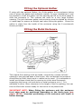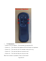
1
PIN NUMBER: 0063-BQ5340 Rev 3 [2010] Compact Fire Ribbon™ With Battery Remote System TECHNICAL INSTALLATION MANUAL Important For use with Natural Gas (G20) or LPG (G31), check data plate within appliance for settings. There are 2 Natural Gas Versions of this Fire that are CE approved. Please refer to data plate for actual heat input of appliance. It is recommended, even if you have fitted these appliances before, that you take the time to read through these instructions and follow them step by step. Serial Number……………………………… Please quote this serial number when calling to discuss technical issues, ordering spare parts or making a warranty claim. Your Warranty is valid for 1 Year from date of delivery. The Warranty card supplied with the appliance should be completed by the installer and returned to the following address. Spirit Fires Limited. Unit 4, Beaumont Square, Aycliffe Industrial Park, Newton Aycliffe, County Durham, DL5 6XN. This manual must be handed to the owner of the property once the fire has been installed and commissioned Page 1 of 50 Contents Page Page Page Page Page Page Page Page Page Page Page Page Page Page Page Page Page Page Page Page Page Page Page Page Page Page Page Page Page Page Page Page Page Page 3 4 5 6 7 8 9 10 11 13 14 14 17 17 18 20 21 22 23 23 23 23 24 25 27 28 29 30 31 32 32 34 34 35 Commissioning Check List Parts List Construction Dimensions Technical Data Introduction Unpacking the Appliance Gas Burner Construction Remote Control System General Installation Information Building and Installation Work Fitting the Optional Gather Fitting the Metal Enclosure Guidance on Ventilation and Ceiling Preparing to Fit the Fascia Fitting the Stone Fascia Fitting the Metal Fascia Commissioning the Fire Final Install checklist Oxygen Depletion Pilot System Spark Failure Burner Flame Warning fire Guards and Hearths Appliance Start Up/Shut Down Instructions Remote Handset Shutdown if the Handset is Faulty and the Fire is Lit Fault Diagnosis/Troubleshooting Battery Remote System – Fault Diagnosis Quick Reference Fault Table Remote Control Components Service and Aftercare Requirements Servicing Instructions Replacement Parts List Burner Removal Gas Fire User Instructions Page 2 of 50 CVO Commissioning Checklist Important Notice Explain the operation of the appliance to the end user, hand the completed instructions to them for safe keeping, as the information will be required when making any guaranteed claims. Pass Fail Flue Check 1. Flue is correct for appliance 2. Flue Flow test 3. Spillage test Gas Check 1. Gas soundness & let by test 2. Standing pressure test 3. Appliance working pressure (on High Setting) NB All other gas appliances must be operating on full 4. Gas rate 5. Does ventilation meet appliance requirements Dealer and Installer Information Dealer……………………………………………… Installation Company……………………… ………………………………………………………… ………………………………………………………… ………………………………………………………… ………………………………………………………… Contact No……………………………………… Engineer………………………………………… Date of Purchase…………………………… Contact No……………………………………… Model No………………………………………… Corgi Reg No…………………………………… Gas Type………………………………………… Date of Installation………………………… This product is guaranteed for 1 year from the date of installation, as set out in the terms and conditions of sale between CVO and your local CVO dealer. This guarantee will be invalid, to the extent permitted by law, if the above Commissioning Checklist is not fully completed by the installer. Page 3 of 50 Parts List – Compact Ribbon • Fire is supplied as a Kit: o Standard Parts Enclosure in Brushed Steel. Front Shelf. Burner Unit with Remote Control Fascia. • Stone has 2 part wall bracket fitted. • Metal fits directly to wall (no bracket) Instruction Booklet Remote Control Handset o Optional Parts Gather Unit Fascia Trim Please check your delivery note. Any missing parts must be notified within 48 hours of delivery. No claims can be accepted after this period. . Page 4 of 50 Construction Dimensions Page 5 of 50 Technical data Specifications Pilot Assembly Marking NG SIT-9103 LPG SIT-9272 Gas connection 8mm O.D. tube Minimum flue diameter 127.0mm Minimum flue height 2.0m Approximate weight N/A Essence Fire Data Gas Type Category Inlet Pressure (Mbar) Injector (X1) Heat Input KW Gross Countries G20 I2H 20 380 6.0 AT, CH, CZ, DK, EE, ES, FI, GB, GR, IE, IT, LT, LV, NO, PT, RO, SE, SI, SK, TR G20 I2E 20 380 6.0 DE, LU, PL, RO G20/G25 I2E+ 20/25 380 6.0/5.5 G25 I2L 25 380 5.5 NL FR, BE G31 I3P (37) 37 125 6.5 BE, CH, CZ, ES, FR, GB, GR, IE, IT, PL, PT, SI, SK, TR G30/G31 I3+ 2830/37 125 6.5 BE, CH, CY, CZ, ES, FR, 6.5 HU, BE, CY, DK, EE, ES, FI, FR, GB, GR, LT, NL, NO, RO, SE, SI, SK, TR G30/G31 I3B/P (30) 30 Page 6 of 50 125 Introduction This appliance is supplied as a complete suite of enclosure of gas fire burner unit, enclosure and fascia. To comply with the approval this fire must be installed as designed. Fascia: The fire must be installed with the fascia “floating” on the wall with the required “air intake” area provided below the shelf as shown in the following pages. The fascia should never be “flush” mounted into the wall otherwise serious burner damage will occur. The fascia must be installed as intended and ventilation to the burner must be provided. Enclosure: Special notice should be taken for metal and stone fascia version fires as the differently. On the metal fascia version the finished wall. On the stone fascia version the proud of the finished wall. the requirements of both the enclosure must be installed enclosure is flush with the enclosure must stand 18mm Gather: An optional gather is available to attach the enclosure to a 127mm class 2 flue liners. This gather should be ordered with the appliance however if this has been missed this can be ordered from Customer Services on 01325-327221. Gas Supply: This appliance requires a steady gas supply within +/- 1mBar of the approved pressure as shown on the data plate at all times. Inlet is via an 8mm gas line. If the gas line is longer than 1.5mtrs then the gas line should be increased in diameter to 15mm and possibly larger depending on the length of gas pipe required. LPG Version: If running this appliance from Gas Bottles the minimum requirement is 2 x 47Kg bottles with a regulator set to the required pressure and a changeover valve. Failure to do this will result in nuisance shutdowns especially in very cold weather. Flame: It is normal with this type of appliance for the flame to be directed towards the back of the enclosure. Flue System: This fire is approved for use with a class 2 / 127mm flue of 2 meters minimum. If a flue system in excess of the specified length is used this may cause a very strong draw to occur which will result in the flame being adversely effected and forced towards the back of the enclosure. This is unavoidable and is a site specific condition and does not indicate an appliance fault. Remote Heat Shield: This fire is approved with the heat shield in place. The fire should never be operated without the heat shield; any resulting damage caused by heat is not covered by the warranty. Page 7 of 50 Unpacking the Appliance Read these instructions fully before proceeding. Carefully examine the carton for damage before proceeding. If it is obviously damaged, please contact supplier over whether to proceed. Remove the fire and examine its general condition. If satisfied by the condition, proceed with the installation. PLEASE NOTE no claims will be accepted for damaged or faulty components once the appliance has been installed. Read the installation instructions fully before starting to install the appliance. The installation should only be carried out by a GAS SAFE registered engineer, and in accordance with national and local regulations for gas. The installation must also be in accordance with relevant parts of local and national building regulations. For the Republic of Ireland, reference should be made to IS813 and ICP3 and any guidance notes from Bord Gais. Failure to have the fire fitted by a qualified person nullifies ALL warranties and guarantees. Page 8 of 50 Gas Burner Construction Take some time to review the burner construction taking note of the positions of the main components and the required connections. Before starting to install the appliance review the Data Plate fitted to the appliance for the gas type and pressure requirements of the appliance. Ensure these are correct for the property supply. This Fire has a battery remote control system and requires only the connection of a 8mm gas supply. The remote is operated via a handset and infra red magic eye positioned on the appliance. Important Note: Gas Supply : The appliance is supplied with an 8mm isolation valve fitted ready for connection to an 8mm inlet tube. Before starting to create the construction opening for the unit provisions for a gas supply need to be made. To maintain a good standing pressure we recommend that a 15mm copper pipe supply be routed as close as possible to the unit with a reduction down to 8mm diameter for the final connection. The 8mm run should be no longer that 1.5m in length. The gas supply pipe should run into the installed enclosure from either the rear, left or right hand sides, the gas supply is best run through the left side of the enclosure. LPG Version. If running this appliance via Gas Bottles then the minimum requirement is 2 x 47Kg bottles with a regulator set to the required pressure and a changeover valve. Failure to do this will result in nuisance shutdowns especially in very cold weather. WARNING The fire is supplied fully tested and working. There should be no need to make any adjustments or to remove any connections from the remote system. Page 9 of 50 Remote Control System Take some time to learn about the remote system fitted to this fire. This Fire remote control system which is powered batteries. The fire is supplied with a hand set to switch the fire on/off and regulate the flame up/down. In order to operate the appliance the handset must be pointed directly at the magic eye (line of sight) on the fire. The hand set has a child safe feature to avoid accidental lighting. Please read “lighting the fire” section later in this handbook before operating the appliance. The remote is powered by 6 x ‘AA’ Batteries in the appliance and a 9V battery in the handset. It is recommended that only “Lithium” batteries are used in the remote system to ensure a long life. Note: that if the fire shuts down it is set in “safe mode” to reactivate the fire press button #1 only on the handset. This will cause a beep. Now the fire can be lit again using the standard start-up sequence. The remote system has a fault diagnosis system built in which is indicated by a number of beeps. Review the “fault diagnosis” section later in this manual for the code. A warning sound when the internal batteries become low will e heard however if the batteries are totally dead there will be no sund. If the appliance fails to operate on the hand set change the batteries in both the appliance and the hand set as this is the most common cause of failure. IMPORTANT NOTE: All CVO fires are given a 100% full function test at the factory before being shipped. Never remove any wires from the black box or the remote system. All connections are required. There is no need to remove any connections from the remote system during installation. Removal of any connections will result in the warranty being invalidated and no claims will be accepted for the unit not working. Page 10 of 50 General Installation Information This fire is intended for decorative purposes. The installation must be in accordance with National Regulations and must be carried out by a qualified installer. Clearances between the fire and all combustible materials must conform to National Regulations. This fire must be installed and used in accordance with these instructions. Prior to installation, ensure that the local distribution conditions (identification of the type of gas and pressure and the adjustment of the appliance) are compatible. The builders opening or fireplace opening must be constructed of a noncombustible material. For some countries a non-combustible hearth must be fitted in front of the fire in accordance with National Regulations (e.g. United Kingdom). For some countries a purpose provided air supply must be fitted in accordance with National Regulations. Any flue damper plate or flue restrictor must be removed or fixed permanently in the fully open position, or shall only be fitted in accordance with National Regulations. The chimney must be swept before the appliance is installed. The unit must not be installed unless the chimney/flue length is at least the distance indicated on page 6 (minimum flue height). Before the fire is installed a flue test in accordance with National Regulations should be carried out. The gas connections must be in accordance with National Regulations. An isolation valve, or valves, has to be fitted adjacent to the appliance which, when closed, allow(s) the complete burner and control assembly to be disconnected for maintenance or repair in accordance with National Regulations. The pilot light and flame sensing device fitted to this fire is also an atmosphere sensing devise. If for any reason any part of the pilot assembly is to be replaced ALL the assembly including the pilot burner, thermocouple, electrode and injector must be exchanged complete for an original manufacturer’s pilot assembly only. This atmosphere sensing devise is not adjustable and must not be put out of action. The pilot light shuts off both the main burner and pilot if evacuation of the combustion products is interrupted. If the fire shuts itself off, do not use the fire, and have the flue and fire checked by a suitably qualified person. Page 11 of 50 For some countries a purpose provided air supply must be fitted in accordance with National Regulations. It is recommended that a guard be used for the protection of young children, the elderly or infirm. This fire should be checked regularly to ensure that it is free from obstruction. A qualified person should service the fire regularly. After installation, the chimney should be inspected and swept regularly to keep the flue clear and free from debris and excessive build up of soot. The fire needs to be covered up when work is undertaken, to ensure the unit does not get damaged or gas outlets blocked. Do not throw rubbish on the unit, as this will block or hamper its efficiency. Due to the newness of the materials, the fire may give off a slight smell for a period of time after commissioning. This is quite normal and any odours should disperse within a few hours of operation. Page 12 of 50 Building and Installation Work A qualified person should complete all building work; a qualified and competent person to all relevant national legislative controls must carry out the installation of gas burners, mechanical extraction, flue systems and remote control units. Building work should only commence after a thorough survey of the intended location of the impending installation has been completed and it has been established that the unit can be installed and operated without risk to the owner or tenants of the property or their neighbours. Where existing chimney systems are to be used in conjunction with the Fire Ribbon, they should have been swept and undergone thorough examination to ensure that they are in a sound and safe condition, as well as providing an adequate draw when the gas fire unit is in operation. A simple smoke test will reveal weather or not the chimney is working correctly. It is important that the gas supply is disconnected before any old existing surround and hearth is removed. The Compact Fire Ribbon enclosure should be located centrally to the existing flue / chimney at your desired height. If the fire is not placed central to the chimney, the flame picture may pull incorrectly. In some installations it is necessary to install a small lintel unit above the opening, if so an allowance must be made to accommodate the lintel. NOTE The Fire Ribbon does not have its own support lintel. NOTE – The support lintel is not supplied with the unit. Important Note: Once installed all additional gas inlet holes in the enclosure [not the front vent] must be sealed with metal tape to avoid flame reversal which will damage the remote. **** VERY IMPORTANT **** Before commencing any work check the type of fascia to be fitted as this will determine the building opening depth required. For a Fire with a Stone Fascia the enclosure front edge must sit 18mm “out” from the finished wall. For a Fire with a Metal Fascia the enclosure front edge must sit flush with the wall. Page 13 of 50 Fitting the Optional Gather If using with the optional Gather, dry fit the gather to the enclosure taking note of where the gather and enclosure overlap. In some installations it may be possible to insert the gather into the opening and lift up to allow space to slide the enclosure in. This reduces the need for a very large builders opening. The joint between gather and enclosure must be sealed by silicone or metal tape to ensure an airtight seal when fitting the gather. Screw the gather in place from the inside of the enclosure using the 6 countersunk screws provided. Fitting the Metal Enclosure The original fire opening must be closed, using bricks / blocks infill the opening to the required base of the burner, the void behind the brickwork should also be filled; block work or rubble can be used. (It is advisable to install a solid base inside the fire opening to sit the steel framework supporting the burner unit and stone or metal enclosure on to.) It is advisable to allow 15mm clearance in the height of the fire opening; this can then be filled with cement ready for the burner to be placed onto. IMPORTANT NOTE: When fitting the enclosure unit the enclosure front edge must be positioned depending on the fascia type (see pages 18-20). Incorrect positioning of the enclosure will result in burner damage. Page 14 of 50 Gas Supply Consult the Data Plate within the appliance to ensure the correct gas type and pressure is available within the property. Before commencing to create the fire opening for the inglenook unit note that a gas supply is required. The gas supply pipe should run into the installed enclosure from either the rear, left or right hand sides, the gas supply is best run through the left side of the enclosure. The fire has an 8mm inlet via an isolation valve. The fire also includes a pressure test point elbow to test inlet pressure. The gas pipe work should be routed into the enclosure via the available access holes. If the gas pipe work is over 1.5mtrs in length it is recommended that the pipe work is increased in diameter from this point to 15mm and possibly 22mm depending on the length to the meter. This will ensure a stable gas supply. Gather The steel gather unit (if required) should now be held up in the opening for preparation on the fitting of the enclosure. Note if the standard gather is not going to be used to exhaust the combustions provisions should be made in accordance with Corgi regulations. Installation Continued The steel enclosure with burner unit is then positioned so that the front edge is positioned as per the fascia type to be fitted (see pages 18-20). Once the steel frame/burner is correctly positioned it is then fixed using fixing screws, which pass through the frame into the newly built fire opening Page 15 of 50 brickwork. The Enclosure must be secure and unable to move. The air intake area at the front of the fire must be left open. The gas supply is now connected and the burner unit is to be tested for safe operation. The front shelf should now be unpacked and fitted. Great care must be taken when inserting the shelves to avoid scratching the inside of the metal enclosure. Page 16 of 50 Guidance on Ventilation and Sealing Air Intake Area/ Burner Ventilation Air is required to the burner unit. This is supplied via the fascia bottom edge. The area between the shelf and the bottom edge of the fascia must not be sealed. This area is required as an “Air Intake Area” Preparing to fit the Fascia The Fascia can now be fitted providing the wall surface is perfectly level both vertically and horizontally. See image left. Important - If the wall is not level, the wall should be skimmed until level. This shows positive areas that can cause fractures in the facia / surround if fitted to a wall of uneven surface. Failure to fit the fascia to a flat wall will cause serious damage to the fascia which is not covered by the warranty. Page 17 of 50 Fitting the Stone Fascia Stone Fascia Hanging Bracket Positioning Note: the Enclosure on the Stone Fascia Version must protrude by a total of 20mm from the wall. If this is not done flame performance will be affected and possible enclosure and burner damage will occur. This is NOT covered by the warranty. The Wall bracket is supplied in 2 pieces. The first part is bonded to the stone at the factory. The second part is fixed to the wall. The fascia is supplied with the wall bracket attached. Remove the 4 cross headed screws, remove the wall bracket and put the fascia and screws in a safe place. Ensure the wall is flush before fitting the fascia. Position the wall bracket as shown below. Measure the dimension as shown below from top of enclosure lintel to the top edge of the wall bracket. The fascia is very heavy and the wall bracket must be secured into a solid surface using suitable screws & rawl plugs to ensure it cannot fall or be pulled from the wall. Ventilation Air Intake For the burner to work correctly there should be an air intake cut-out below the front shelf as shown in the above image. This air void provides burner ventilation to ensure the flame remains stable and the remote system remains cool. The Air Flow is provided via the from fascia lower intake. Failure to ensure this will result in serious damage to the remote system. This damage is not covered by the warranty. Page 18 of 50 Hanging the Stone Fascia & Fitting Magic Eye With the help of an assistant, lift the fascia into place. Unclip the remote magic eye and plug into the remote control (as shown on wiring diagram). Once the remote is attached lift the fascia on to the wall bracket. Refit the 4 cross headed screws and ensure fascia is secure. WARNING: The fascia must never be sealed or built flush into the wall. The Fascia has an air vent at the lower edge. This with Air Intake provides ventilation to the burner unit. If this is blocked or the fascia not fitted in the way shown then serious damage to the burner and remote system will result which is NOT covered by the warranty. The Finished fascia should look like the image below. If this is not the case then it is not fitted correctly and the fire will not function as designed. The fascia must never be fitted “flush” to the wall. See image below. Page 19 of 50 Fitting the Metal Fascia • • • • • • • • • • • See information above for details of the Air Intake requirements. WARNING: the Enclosure on the Metal Fascia must be flush with the wall before attempting to fit the fascia. Put the fascia against the wall so that the lower edge is level with the shelf. Draw around the fascia. Remove fascia and turn over. Measure positions of screw key holes and mark this onto the wall. Drill and Plug holes. Fit Suitable Screws to a depth to ensure the fascia locks against the wall when fitted. With the help of an assistant, lift the Fascia towards fire. Unclip the remote magic eye and plug this into the remote box as shown on the wiring diagram. Lift fascia onto the wall until key holes line up then pus fascia down to lock in place. WARNING: The metal fascia must sit off the wall 40mm. It must never be installed “flush” into the wall or plaster. The fascia has an air vent which runs along the bottom. This plus the specified air intake area ensure the burner and flame perform as required. Failure to do this will result in serious burner damage which is NOT covered by the warranty. Page 20 of 50 Commissioning the Fire This appliance requires a specific amount of ventilation to function as designed (correct flame picture), therefore any unused utility access points in the burner tray must be sealed with Aluminium foil tape. When installing the enclosure into an existing chimney or with a flue liner the enclosure & gather must be sealed to the existing chimney to ensure that air cannot flow behind the enclosure (flame reversal). Failure to do this will result in serious damage to the burner unit and enclosure. This damage is not covered by the warranty. Use the commissioning sheet on page 3 completing each section in turn. Refer to the “lighting the fire” section later in this handbook to learn the remote system and sequence. Note: This fire must not be operated without the heat shield in place over the Black Box. Failure to do this will result in serious damage to the remote system which will not be covered by the warranty. TEST THE GAS PRESSURE: Turn the fire on full; attach a manometer to the inlet test point and ensure there is a pressure of 20mb (+/- 1mb) for natural gas appliances or 30mb or 37mb for propane appliances. Now turn on all the other gas appliances in the house and re check pressure. The pressure must still be within the tolerance of +/- 1mb. Now turn off all the other gas appliances and turn the fire down to pilot only, the pressure must still be in the tolerance of +/- 1mb. If its not, TRANSCO, BORD GAIS or the propane supplier must be called to adjust the governor to the house before the fire can be commissioned further. TEST THE FLUE: The installer must check that all of the combustion products are entering the flue after 10 minutes by traversing the perimeter of the fireplace opening using a smoke “match”. Ensure the flue and enclosures are sealed. Page 21 of 50 BRIEF THE CUSTOMER: • How to light and shut down the appliance. • How to change the hand set batteries. • How to change the main appliance batteries. • The customer must be told of the need for regular servicing of the appliance, at least once a year. • The customer must be made aware that no rubbish is to be thrown onto the fire bed. • The customer must also be aware that purpose provided ventilation should be checked regularly. • Complete the warranty card and give this to the customer. • Give the customer the instruction booklet. Final Install Check List • • • • • • • • Are the Flue & Enclosure sealed to ensure no air can travel around the sides or back of the enclosure? Are all other access holes in the burner tray sealed with metal tape? Is the heat shield fitted? Has the customer being shown how to operate the appliance? Has the customer been shown how to replace the handset and main appliance batteries? Has the commissioning sheet on page 3 been completed? If you have any questions, or the fire is not operating correctly, contact the manufacturer on 01325-327221 before you leave the installation. If the appliance is not fitted in strict accordance with these instructions, CVO cannot be held responsible for any damage caused and reserve the right to charge for any corrective work. Page 22 of 50 Oxygen Depletion Pilot System There is a highly sensitive oxygen depletion sensor designed into the pilot light. If any part is damaged the entire unit must be replaced. Do not attempt to bend or alter the flame head, thermocouple or aeration hole. Use only genuine spare parts as similar looking parts from other appliances may well give different or inferior performance and could lead to a hazard. Spark / Ignition Failure The gap between the pilot electrode and the pilot should be 3.5 – 4.5mm and normally adjustment is not necessary (the electrode is very brittle). The spark should jump across the gap between the electrode and the gas outlet on the pilot head. If the ignitor fails, a lighted taper can be inserted into the pilot area to check that gas is reaching the pilot. Burner Flame The flame on this type of appliance is normally directed towards the rear of the enclosure. This is normal due to the opening size and flue system. The flame will never stand “upright”. It is to be expected that over time the surface on the rear of the enclosure will tarnish. This is typical “wear and tear” for a gas fire. If the flame is drawn under the shelf this highlights a serious installation fault and the appliance must not be operated until the cause is found. A typical cause would be unsealed burner holes or failure to seal the enclosure and flue (flame reversal). Any resulting damage is not covered by the warranty which covers “defective” parts only. Warning: Fire Guards & Hearths This appliance is not fitted with an integral guard. In normal use consideration may be given to the use of a fireguard conforming to BS6539 or BS6778, so that the approach to the appliance is limited such that access to the flame is minimised. It is recommended that a fireguard conforming to BS6539 or BS6778 is used for the protection of young children, the elderly and infirm. The installer is to advise the user not to stand too close to the appliance for prolonged periods of time and warn that loose clothing is particularly at risk of burning due to the presence of an unguarded flame. In addition, the installer is to advise the user against placing combustible material directly in front of the appliance. Floor coverings, such as carpets, are considered to be acceptable. For some countries a non-combustible hearth must be fitted in front of the fire in accordance with National Regulations (e.g. United Kingdom). Page 23 of 50 Appliance Start Up / Shut Down Instructions The appliance is supplied with an internal battery power supply and is operated via handset. There are 6 x ‘AA’ batteries inside the appliance and 1 x 9V battery in the handset. Only use good quality batteries to ensure a long life. If the main burner or pilot light is extinguished during lighting, do not attempt to re-light the pilot within three minutes. To Reset the Appliance: If the appliance is shut down unexpectedly the valve must be reset first before the fire can be re-lit. This can be done by pressing the “OFF” (button #1) until a beep is heard. Wait a few seconds then commence the starting sequence as detailed below by pressing both left had buttons at the same time. Using the Handset (see image). • • • To Light the Fire – As a “child proof” system both buttons #1 & #2 must be pressed at the same time for a number of seconds until the ignition (spark) sequence starts. To operate correctly the handset must be pointed directly at the magic eye on the appliance. When the pilot flame presence is detected (ionization flame control) the system holds for 10 seconds to warm the thermocouple. Once the thermocouple is warm enough to hold the magnet unit the valve will allow gas to the burner at the maximum setting. In case of failure during pilot ignition sequence, the EDB puts the system in safe mode. To restart the ignition sequence press Button #1 again. Standby Mode - It is possible once the fire is lit to operate in standby mode with pilot only lit. To do this press button #2. • High Setting - By pressing Button #3 the burner flame is increased to the maximum rate. • Low Setting - By pressing Button #4 the burner flame can be reduced to the minimum rate. • Turn Off - To turn the appliance OFF Button #1 is pressed. Each time a button is pressed a “beep” will be heard. Page 24 of 50 To Summarise: o Button #1 & #2 together – This switches the appliance ON. o Button #1 – This switches the appliance OFF and Resets the Appliance. o Button #2 – This sets the unit into standby mode (pilot only) o Button #3 – This sets the flame at maximum rate. o Button #4 – This sets the flame at minimum rate. Each time a button is pressed a “beep” will be heard. Page 25 of 50 Using the Manual Control Panel (if fitted). Included with the fire is a manual switch membrane which can be stuck to the wall. Please ensure that the switch and cable do not become detached during assembly. Refer to the remote fault diagnosis if the unit “beeps” repeatedly. If the switch is not to be used or fitted the remote “link” must be fitted to the remote black box. The fire will not operate without either the switch or the link. • Button #1 - By pressing this switch, this starts the ignition sequence (press & hold for 3 sec minimum). The gas to the pilot is open and the magnet unit pressed by the motor, the spark is generated. When the pilot flame presence is detected the system holds for 10 seconds to warm the thermocouple. • Once the thermocouple is warm enough to hold the magnet unit the valve will allow gas to the burner at the maximum setting. • In case of failure during pilot ignition sequence, the EDB puts the system in safe mode. To restart the ignition sequence press Button #1 again. • It is possible once the fire is lit to operate in standby mode with pilot only lit. To do this press button #2. • By pressing Button #3 the burner flame is increased to the maximum rate. • By pressing Button #4 the burner flame can be reduced to the minimum rate. • To turn the appliance OFF Button #1 is pressed. • Each time a button is pressed a “beep” will be heard. NOTE: If the appliance is shut down unexpectedly the valve must be reset first before the fire can be re-lit. To do this press the “OFF” button until a beep is heard. Then commence the starting sequence as detailed above by pressing both left had buttons at the same time. The pilot is a safety device which monitors the gas pressure and flue conditions. If a fault in either of these areas are detected the pilot will not allow the fire to be lit. Please review the installation conditions before proceeding. Page 26 of 50 Shutdown if the Handset is Faulty and the Fire is Lit The appliance has a safety shut down switch which is built into the remote system. This is in the form of a button fitted inside the appliance. In the unlikely event that the wall switch is not fitted and handset is lost, damaged or broken while the fire is lit the fire can be shutdown by pressing this button. Safety Shutdown Procedure • • • Carefully lift the front shelf taking care that the appliance will be hot. The reset button is fitted to the top of the remote shield. Carefully insert hand below the shelf taking care not to touch any hot surfaces. • Press and hold the button for up to 60 seconds. • The appliance will shut down. • Taking great care not to touch any hot surfaces carefully remove your hand and replace the front shelf. • Do not use the appliance until the handset has been repaired or replaced. • To purchase a new handset call 01325-327221. Page 27 of 50 Fault Diagnosis/Troubleshooting Symptom The system “beeps” all the time. Appliance clicks but no spark or weak spark. Check List There is a fault diagnosis system built into the battery remote. The remote gives out a sequence of “beeps”. This is a code which indicates a fault. See section 13 for details. Check spark lead is connected properly. Check spark electrode is in the correct area and the gap correctly distanced to the pilot. Check for a good spark. Check the spark is in the right area. Appliance sparks but does not light pilot. If there is no gas. Check that the ventilation is not too strong and drawing the gas away from the pilot. Check that there is gas at the input and at the pilot. Check that remote valve is operating correctly. Check isolation tap/shut off is open. Check for blockages in the gas pipes. Check for a good spark. If there is gas but pilot does not light Check the spark is in the right area. Check that the ventilation is not too strong and drawing the gas away from the pilot. Check the pilot gas slot is clear. Check the pilot flame is heating the thermocouple. Pilot lights but does not light main burner Check the thermocouple nut is properly tightened into the valve. Check that the pilot lights early on ignition clicks. Check ventilation is not too strong and drawing the pilot flame away from the thermocouple. When using LPG Bottles ensure bottle is not empty. To run this appliance on bottles a minimum of 2 x 47KG bottles with a changeover valve is required. The bottles must have a suitable regulator. Burner lights but turns off after a few minutes Check thermocouple nut is properly secured to the valve. Check ventilation is not too strong and the flame is not blowing off the thermocouple. Check gas pressure is correct and maintained at constant level – especially with other appliances in the home working. Page 28 of 50 Tick Battery Remote System – Alarm Sequence This fire is operated via a battery remote system with AA batteries. The remote system has a built in alarm system which indicates and faults which may arise. A fault is indicated by a sequence of a pre-defined “beeps”. The number of beeps corresponds to a certain failure. NOTE: There are two types of black box fitted to this type of appliance. See the black box to identify which one is fitted to your fire. BLACK BOX – EDB20 Alarm sound description 2 x Beeps = Low battery alarm. In case of low battery voltage (supply voltage below 6V) the buzzer produces a sequence of 2 beeps with a repetition rate of 1s. To resume the normal operation it’s necessary to recharge or substitute the battery with a new one and to verify the alarm sound is no more present. 3 x Beeps = Manual Wall Keyboard failure sound. In case of keyboard failure (i.e. cable opens or pushbutton stuck closed) the buzzer produces a sequence of 3 beeps with a repetition rate of 1s. To resume the normal operations it’s necessary to substitute the keyboard with a working one and to verify the alarm sound is no more present. 4 x Beeps = Motor Failure sound. In case of motor failure, the buzzer produces a sequence of 4 beeps with a repetition rate of 1s. To resume the normal operations it’s necessary to substitute the valve with a working one, to repeat the ignition sequence and to verify the alarm sound is no more present. 5 x Beeps = Driver leakage sound. In case of on board motor driver current leakage failure the buzzer produces a sequence of 5 beeps with a repetition rate of 1s. To resume the normal operation it’s necessary to substitute the board with a working one, to repeat the ignition sequence and to verify the alarm sound is no more present. 6 x Beeps = Under voltage low battery. In case on under voltage low battery (supply voltage less than ADC circuit reference power supply); the buzzer produces a sequence of 6 beeps with a repetition rate of 1s. To resume the normal operations it’s necessary to substitute the battery with a new one and to verify the alarm sound is no more present. Page 29 of 50 BLACK BOX – IR/RF Alarm sound description 7 x beeps – Low Battery Substitute the battery with a new one and verify the sound alarm stops. Before inserting the new battery pack, remove the old one and wait until the sound disappears. Wait at least 2 minutes before adding the new batteries. If the sound is still present after adding new batteries, execute an ignition sequence. 3 x beeps – Manual Wall Switch Keyboard Failure Substitute the keyboard with another one and verify the sound alarm stops. 4 x beeps – Valve Motor Failure Substitute the valve with another one. Repeat the ignition sequence and verify the sound alarm stops. 5 x beeps – Driver Leakage [Black Box Faulty] Substitute the board: the motor drive circuit is damaged. Execute an ignition sequence and verify there’s no sound alarm. 6 x beeps – Under Voltage Low battery Substitute the battery with a new one and verify the sound alarm stops. Before inserting the new battery pack, remove the old one and wait until the sound disappears. Wait at least 2 minutes before adding the new batteries. If the sound is still present after adding new batteries, execute an ignition sequence. Battery Replacement: When replacing the batteries they must be replaced as a complete set and a full new set used. The system has a memory and if any old batteries are used the alarm sequence will not be reset. To reset the alarm: Remove the old batteries. Wait 10 minutes. Fit a set of 6 new Alkaline or Lithium batteries. Start the fire. Page 30 of 50 Remote Control Components Page 31 of 50 Service and Aftercare Requirements When completing the annual service of the unit, refer to the enclosed technical installation and operational manual & the remote control instruction document. The gas unit should be installed to the manufacturer’s instructions by a Gas Safe registered gas installer, every 12 months the gas fire unit should undergo a regular service, this work should be carried out by a competent person who is Gas Safe registered, familiar with the CVO Fire range of goods. When carrying out the annual service, the competent person should examine and verify the following; • • • • • • The correct safe operation of the ODS (oxygen depletion system) That the fire unit correctly cross-lights A pressure drop test to verify that there are no gas leaks That the electronic ignition system operates correctly That the burner surface is free from damage and debris That the owner has a copy of the installation and operation manual Servicing Instructions General CVO Recommend that this appliance is serviced every 12 months by a GAS SAFE Engineer. The following servicing procedure should be carried out regularly and only by a qualified person. Note: foreign bodies, which can gather on the surface of the burner unit, it is inevitable that servicing can be a dusty operation. Suitable precautions should be taken. Important: The pilot and flame sensing device fitted to this fire is also an atmosphere sensing device. If for any reason any part of the pilot assembly is to be replaced, the entire assembly including the pilot burner, thermocouple electrode and injector must also be exchanged. This atmosphere sensing devise is not adjustable and must not be disabled. Page 32 of 50 Servicing Procedure • • • • • • • • • • Turn off the fire and allow cooling time. Turn off the gas supply at the isolation tap. Remove the fascia. Using a Phillips style screwdriver, loosen the screws on the mixer tube then undo the injector nut, and remove the injector. Clean the injector and remove blockages. Do not use a needle or wire, as this may widen the journals, which are set to the C V O test standards. Using a soft brush or vacuum cleaner, carefully remove any debris from the burner unit. Make sure the pilot journals are clear and free from dirt. Re-assemble the fire in the reverse order, and re-connect the gas supply then check for soundness. Check the pilot for a good flame. Re-commission the fire (See section earlier in this booklet). For Spare Parts please call 01325-327221 and ask for customer service. Page 33 of 50 Replacement Parts List There are no “user” replacement parts available for this fire. The fitting of replacement parts must be carried out by a qualified GAS SAFE Engineer inline with current regulations. Item description 8mm Isolation Tap Pilot Natural Gas (Manual) Pilot Propane/LPG (Manual) Injector Natural gas Injector LPG Remote Control Parts Code AC026 SIT-NG-9103 SIT-LPG-9272 Stereomatic – 380 Stereomatic – 1.25mm Available upon request Note: spare parts are not returnable. CVO Fire cannot accept responsibility for incorrect parts being ordered. When ordering replacement components or requesting technical assistance, you should quote the following information: Type of fire, the gas type, the serial number as shown on Data Plate, plus the component part number or description of fault Fitting Spare Parts : When removing any parts from the remote system these should be replaced in the same manner using the “schematic diagram” in this booklet. When changing the injectors or pilot great care must be taken to assemble the parts in the correct manner to ensure the fire functions as designed. Burner Removal Removal of the burner during installation will invalidate the warranty. Speak to our technical department. If the burner needs to be removed at anytime for repair follow the steps below: • With the help of an assistant carefully remove the fascia. This will be different depending on type – metal or stone. (see install method earlier in this booklet). Great care must be taken as the remote magic eye is fitted to the fascia. • Lift the fascia from the wall sufficient to allow the magic eye to be unclipped from the black box remote. • Place the fascia in a safe position. • Lift out the front shelf taking care not to scratch the enclosure. • Remove the 2 screws on each side which hold the shelf mounting brackets to the enclosure. • Isolate and disconnect the gas supply. • The burner carriage is screwed to the bottom of the enclosure by 2 screws. Once removed the full burner assembly will lift out. • Refit is the same procedure in reverse. • The fire should be commissioned once refitted. Page 34 of 50 COMPACT FIRE RIBBON with Battery Remote System GAS FIRE USER INSTRUCTIONS & GUIDE For use with Natural Gas (G20) or LPG (G31) This manual must be handed to the owner to the owner of the property once commissioned Page 35 of 50 Contents Page Page Page Page Page Page Page Page Page 37 38 39 42 43 44 45 46 50 General Information Lighting the Fire Appliance Start Up / Shut Down Instructions Shutdown if the Handset is Faulty and the Fire is Lit Replacing the Batteries Cleaning Instructions Warranty Information Fitting the Optional Wall Switch-Fires with Battery Remote Contact Details Page 36 of 50 General Information A qualified GAS SAFE registered installer is required to fully install the appliance, failure to do this may render the appliance dangerous and will invalidate the warranty. This fire is intended for decorative purposes. Any purpose-provided ventilation should be checked regularly to ensure that it is free from obstruction. The fire should be serviced regularly by a qualified person. The chimney should be swept before the appliance is installed, and should be swept and inspected regularly to ensure that all of the products of combustion are entering the flue and there is no excessive build up of soot. Do not throw rubbish et cetera upon the burner surface. Debris from any source, or soot formed, should be removed from time to time, see ‘Cleaning instructions’. If any of its parts are damaged and need to be exchanged the original manufacturers parts must be used. Pilot Assembly: The pilot light and flame sensing device fitted to this fire is also an atmosphere sensing device, which shuts off both the main burner and pilot if evacuation of the combustion products is interrupted. If the fire shuts itself off, restart the fire following the procedure in section ‘Lighting the fire’. If the fire continues to shut itself off do not use the fire, and have the flue and fire checked by a suitably qualified person. The pilots ODS (Oxygen depletion sensor) must not be put out of operation. The user must not adjust the pilot. Once the flue and fire units have been checked and remedial action taken, the fire is ignited in the manner depicted in section ‘Lighting the fire’. Due to the newness of materials, the fire may give off a slight smell for a period of time after commissioning. This is quite normal and any odours should disperse within a few hours of operation. For some countries a purpose provided air supply must be fitted in accordance with National Regulations. This fire should be checked regularly to ensure that it is free from obstruction. A qualified person should service the fire regularly. Fire Guards : It is recommended that a fireguard conforming to BS6539 or BS6778 is used for the protection of young children, the elderly and infirm. Page 37 of 50 Lighting the Fire Infra-Red Remote Operation Infrared systems require “Line of sight” between the handset and the sensor at the appliance, it is a standard safety feature to ensure that the appliance cannot be remotely lit from another room. Page 38 of 50 Appliance Start Up / Shut Down Instructions The appliance is supplied with an internal battery power supply and is operated via handset. There are 6 x ‘AA’ batteries inside the appliance and 1 x 9V battery in the handset. Only use good quality batteries to ensure a long life. If the main burner or pilot light is extinguished during lighting, do not attempt to re-light the pilot within three minutes. To Reset the Appliance: If the appliance is shut down unexpectedly the valve must be reset first before the fire can be re-lit. This can be done by pressing the “OFF” (button #1) until a beep is heard. Wait a few seconds then commence the starting sequence as detailed below by pressing both left had buttons at the same time. Using the Handset (see image). • • • To Light the Fire – As a “child proof” system both buttons #1 & #2 must be pressed at the same time for a number of seconds until the ignition (spark) sequence starts. To operate correctly the handset must be pointed directly at the magic eye on the appliance. When the pilot flame presence is detected (ionization flame control) the system holds for 10 seconds to warm the thermocouple. Once the thermocouple is warm enough to hold the magnet unit the valve will allow gas to the burner at the maximum setting. In case of failure during pilot ignition sequence, the EDB puts the system in safe mode. To restart the ignition sequence press Button #1 again. Standby Mode - It is possible once the fire is lit to operate in standby mode with pilot only lit. To do this press button #2. • High Setting - By pressing Button #3 the burner flame is increased to the maximum rate. • Low Setting - By pressing Button #4 the burner flame can be reduced to the minimum rate. • Turn Off - To turn the appliance OFF Button #1 is pressed. Each time a button is pressed a “beep” will be heard. Page 39 of 50 • To Summarise: o Button #1 & #2 together – This switches the appliance ON. o Button #1 – This switches the appliance OFF and Resets the Appliance. o Button #2 – This sets the unit into standby mode (pilot only) o Button #3 – This sets the flame at maximum rate. o Button #4 – This sets the flame at minimum rate. Each time a button is pressed a “beep” will be heard. Page 40 of 50 Using the Manual Control Panel (if fitted). Included with the fire is a manual switch membrane which can be stuck to the wall. Please ensure that the switch and cable do not become detached during assembly. Refer to the remote fault diagnosis if the unit “beeps” repeatedly. If the switch is not to be used or fitted the remote “link” must be fitted to the remote black box. The fire will not operate without either the switch or the link. • Button #1 - By pressing this switch, this starts the ignition sequence (press & hold for 3 sec minimum). The gas to the pilot is open and the magnet unit pressed by the motor, the spark is generated. When the pilot flame presence is detected the system holds for 10 seconds to warm the thermocouple. • Once the thermocouple is warm enough to hold the magnet unit the valve will allow gas to the burner at the maximum setting. • In case of failure during pilot ignition sequence, the EDB puts the system in safe mode. To restart the ignition sequence press Button #1 again. • It is possible once the fire is lit to operate in standby mode with pilot only lit. To do this press button #2. • By pressing Button #3 the burner flame is increased to the maximum rate. • By pressing Button #4 the burner flame can be reduced to the minimum rate. • To turn the appliance OFF Button #1 is pressed. • Each time a button is pressed a “beep” will be heard. NOTE: If the appliance is shut down unexpectedly the valve must be reset first before the fire can be re-lit. To do this press the “OFF” button until a beep is heard. Then commence the starting sequence as detailed above by pressing both left had buttons at the same time. The pilot is a safety device which monitors the gas pressure and flue conditions. If a fault in either of these areas are detected the pilot will not allow the fire to be lit. Please review the installation conditions before proceeding. Page 41 of 50 Shutdown if the Handset is Faulty and the Fire is Lit The appliance has a safety shut down switch which is built into the remote system. This is in the form of a button fitted inside the appliance. In the unlikely event that the wall switch is not fitted and the handset is lost, damaged or broken while the fire is lit the fire can be shutdown by pressing this button. Safety Shutdown Procedure • • • Carefully lift the front shelf taking care that the appliance will be hot. The reset button is fitted to the top of the remote shield. Carefully insert hand below the shelf taking care not to touch any hot surfaces. • Press and hold the button for up to 60 seconds. • The appliance will shut down. • Taking great care not to touch any hot surfaces carefully remove your hand and replace the front shelf. • Do not use the appliance until the handset has been repaired or replaced. • To purchase a new handset call 01325-327221. Page 42 of 50 Replacing the Batteries Main Appliance Batteries If the remote alarm indicates that the batteries are “flat” do not use the appliance. Ensure the appliance is switched off and has had time to “cool down”. Lift the front shelf of the appliance taking care not to scratch the sides of the enclosure. The battery pack will be visible. Lift the battery pack from its holder and remove the flat batteries. Insert 6 x AA batteries in the correct order and replace the battery pack in the holder, ensuring that no wires are disconnected. Refit the front shelf. Hand Set Batteries Turn over the hand set and unclip the battery cover. Fit a new 9V battery and refit the battery cover. The appliance should now operate normally. NOTE: CVO Fire recommends that only high quality batteries are used in this appliance. Lithium batteries provide the longest life. Page 43 of 50 Cleaning Instructions Before cleaning the appliance turn off the Fire unit and allow it to cool for a number of hours. Before using any cleaning materials test a small area first to ensure compatibility with the appliance finish. CVO Fire cannot be held responsible for damage caused by cleaning the appliance. Burner Bar / Deposits It is normal for the burner bar to show a redish or white deposit. This is caused by bi-products of the gas being burnt and is unavoidable. This can be remedied by using a stove paint like Hotspot High Temperature Stove Paint which is sold in 100ml cans online for approx £7. Similar products may also be available from major DIY stores or fireplace retailers. It may be required to paint the burner bar every 6 months or so depending on usage. Cleaning the Gas Fire Burner and Enclosure The most effective method of dust/debris removal is achieved with the aid of a vacuum cleaner however; great care must be taken to ensure that the pilot assembly is not touched. Using a vacuum cleaner with a soft brush head gently remove any debris/dust from inside the enclo0sure and around the burner unit. Once all of the dust and debris has been removed the surfaces can be cleaned with the use of a soft cloth and a hand held “stainless seel” cleaner which is available from most supermarkets. Cleaning the Metal Fascia This can be done with a soft cloth and a hand held “stainless steel” cleaner which is available from most supermarkets. Cleaning the Stone Fascia This can be done with a soft cloth and “stone cleaner” which is available from most supermarkets. Removing spillages This appliance has an electronic remote system. Where a liquid has been spilled onto the surface of the fire or enclosure DO NOT USE THE APPLIANCE – contact your installer to ensure the remote system functions correctly. Wax Never place candles on the burner shelves. If molten wax enters the burner unit – DO NOT USE THE APPLIANCE - contact your installer to remove the spillage and ensure the remote system functions correctly. Page 44 of 50 WARRANTY INFORMATION This appliance carries full CE approval and has a long and reliable history. The CE approval ensures that, if installed correctly, the appliance will function as designed. If the appliance develops a fault please refer to the fault diagnosis section earlier in this booklet for possible causes. This appliance is supplied with a 12 month warranty from the date of delivery. The Warranty covers defective parts only and does not cover typical wear and tear that occurs with a gas fire appliance. In order to make a warranty claim you will be required to supply the serial number of the appliance [as shown on the front of this book] and full details of the GAS SAFE engineer who installed the appliance - we may request a copy of the installation receipt. Failure to supply details of the Registered Engineer who installed the appliance will invalidate the warranty. To register your appliance please complete and return the warranty card supplied with the fire. To raise a warranty claim call Customer Service on 01325-327221. IMPORTANT NOTE - “Heat Damage” This fire must never be operated without the heat shield in place over the Black Box. Failure to do this will result in serious damage to the remote system. We will not accept any claims for “melted remote system”. In this instance in highlights a very serious issue over the installation of the appliance. The appliance has been tested to CE standards to ensure, when installed correctly, that all of the components operate within the designed temperatures. In the instance of the remote system becoming hot enough to melt it highlights an install fault not a component failure. Typical causes are – using the fire without the heat shield, incorrect burner ventilation, unsealed enclosure, an unsealed flue system or flame reversal. Before purchasing new parts to repair the fire the cause of the melting must be rectified. We will not accept any claims where connections have been tampered with. Page 45 of 50 the burner wiring or Fitting the Optional Wall Switch For Fires with Battery Remote Important This work must be carried out by a GAS SAFE REGISTERED ENGINEER. Page 46 of 50 Remote Diagram Take some time to review the attached diagram NOTE THE POSITION OF THE “LINK” Page 47 of 50 INSTRUCTIONS 1. Use the gas isolation valve to isolate the gas. 2. Taking care not to damage any components on the circuit board remove the heat shield. 3. Note the position of the link in the circuit diagram. 4. Gently remove the link and replace this with the wall switch cable. 5. Route the cable as require ensuring that it is kept away from hot surfaces. 6. Secure the wall switch in the required place and connect the cable. 7. Refit the heat shield on the remote system. 8. Reconnect gas 9. Review the section on “lighting the fire” to ensure the wall switch operates correctly. 10. Operate fire as normal. VERY IMPORTANT NOTE If the link “or” the wall switch is not fully connected to the remote the remote system will not work. To confirm: THE LINK MUST BE FITTED Or THE WALL SWITCH MUST BE FITTED CVO Fire will not accept any warranty claims resulting from damage caused by fitting or removing the manual wall switch from the fire. Page 48 of 50 Page 49 of 50 ONLY USE GENUINE REPLACEMENT PARTS. Spirit Fires Ltd, 4 Beaumont Square Aycliffe Industrial Park, Newton Aycliffe County Durham, DL5 6XN T – 01325 327 221 F – 01325 327 292 www.cvo.co.uk The information supplied in this manual is correct at the time of publication; Dated on the 12-12-2010. There may be changes made in future as we improve our products. If there are any queries about this appliance please email [email protected] or call our technical department on 01325-327221. Visit our web site for further details of our products Page 50 of 50