1
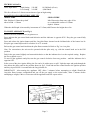
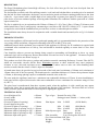
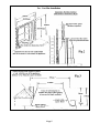
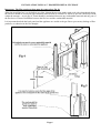
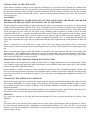
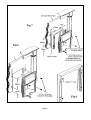
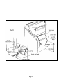
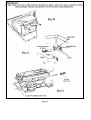
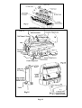
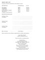
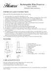
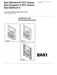
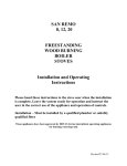
81139
Issue 3
52<$/&+(/7(1+$0
USERS INSTRUCTIONS
THIS CAT I2H APPLIANCE IS FOR USE
ON NATURAL GAS G20 AT A SUPPLY
PRESSURE OF 20 mbar GB and IE
HAND THESE INSTRUCTIONS TO THE USER
DESCRIPTION
The Royal Cheltenham glass fronted high efficiency live fuel effect inset gas fire has been developed from the
successful Royal Cozyfires LFE using much of the technology and components used in the manufacture of this
appliance.
The fuel bed has a realistic coal effect utilizing ceramic ‘coals’ and coal bed that allows secondary air to be
entrained into the bed for clean combustion. The burner is an aerated twin ported steel burner running parallel
across the front of the fire. The gas control fitted has a variable high to low setting and includes the added
protection of a flame supervision device. A separate piezo igniter used to ignite an Oxy/pilot device to prevent
continued spillage occurring under hazardous flue conditions.
The installation must be carried out by a competent person in accordance with the relevant British Standards,
Codes of Practice and Gas Safety (Installation and Use) Regulations 1994 or the rules in force. Failure to install an
appliance correctly could lead to prosecution.
Before the appliance is installed, the installer must check that all the requirements for the flue are satisfied and that
the chimney is sound and clean, and that it has been swept prior to installation.
IMPORTANT NOTES
FIREGUARD The glass window on this gas fire is manufactured to the requirements of BS 1945 1971, and
satisfies the Heating Appliances (fireguards) (safety) Regulations 1991. The Royal Cheltenham is a heating
appliance and as such some areas of the appliance will become hot. It is recommended that a fireguard to BS 6539
1984, is used for the protection of young children, the elderly and the infirm.
THIS APPLIANCE IS FITTED WITH SPECIAL HEAT RESISTING GLASS PANELS, IF ANY PANEL IS
DAMAGED THE FIRE MUST NOT BE USED AND A REPLACEMENT SPARE PANEL MUST BE
OBTAINED TO CARRY OUT THE REPAIR.
It is very important that the warm air outlet grilles are not obstructed or used for drying towels etc.
When the fire is new, an initial odour may be detected. This is due to certain materials used during the
manufacture of the fibre components, increase the ventilation to the room during the initial burn-in.
The stainless steel used for the construction of the combustion chamber may become discoloured (blued). This is
due to the temperatures and does not detract from the effectiveness of the fire.
This product uses fuel effect pieces, gaskets and insulation material containing Refractory Ceramic Fibre
(RCF), which are man-made vitreous silicate fibres. Excessive exposure to these materials may cause
temporary irritation to eyes, skin and respiratory tract, consequently, it makes sense to take care when handling
these articles to ensure that the release of dust is kept to a minimum.
Care must be taken on the selection of the wall coverings within close proximity of the fire as some vinyl’s and
embossed materials may become discoloured by convected heat. Soft furnishings must be kept clear from the
radiant heat of the fire and from impinging the hearth area. The hearth must not be covered by any combustible
materials such as carpet, etc.
It is recommended that the appliance is serviced annually by a competent person, the flue checked for satisfactory
clearance of combustion products and that there is no excessive build-up of soot. An inspection should be made for
any build-up of soot or debris falling behind the unit that could prevent products of combustion being drawn into
the flue.
Any existing or purpose built ventilation must be kept clear and free from obstruction.
Page 2
TECHNICAL DATA
Heats Input Rates:
High Setting
Low Setting
5.42 kW
2.34 kW
18,500 Btu/h (Gross)
8,000 Btu/h
This fire will run for 5.4 hours on one therm of gas on high setting.
LOCATION OF COMBUSTIBLE SHELVES
ABOVE FIRE
SIDE OF FIRE
Min. Height of 150mm deep shelf
above hearth = 830mm
Min. Dimension from outer edge of fire
to a combustible surface of 150mm
depth is 100mm.
When the shelf depth is increased by increments of 12.5mm, add 25mm to the height above fire.
TO LIGHT APPLIANCE (see Fig 1)
Remove the Fret (controls cover) to gain access.
Press and turn the gas control knob anticlockwise until the indicator is opposite IGN. Keep the gas control fully
depressed.
Press and release the igniter button until the Oxy/pilot flame situated on the left-hand side of the burner has lit.
Keep the gas control depressed for a further 10 to 15 seconds.
Release the gas control and check that the pilot flame remains lit. Refer to Fig 3 to view pilot.
Note. For convenience, the unit can be operated with the pilot only, e.g. with the control knob set in the IGN
position.
Push in the gas control slightly and turn anticlockwise so that the indicator dot is at the required setting. Replace
the Fret (controls cover).
To turn off the appliance and pilot, turn the gas control clockwise from any position - until the indicator dot is
opposite OFF.
In the event of the piezo igniter failing, the fire can be lit with a taper or spill. Light the taper and push through the
slots below the glass panel in the position shown in fig 2. Push and turn the control knob to the ignition position
and keep it pressed for 10 seconds after the Oxy/pilot has lit.
IMPORTANT: After turning the appliance OFF, allow 3 minutes before attempting to relight. Should the
Oxy/pilot flame become extinguished and cut off the gas supply to the main burner, allow 3 minutes before
attempting to relight, if this re-occurs turn off the appliance and seek expert advice.
Page 3
DISMANTLING THE FIRE BED FOR CLEANING (see fig.3, 4 & 5)
Allow the appliance to cool for 1 hour before handling any components. Remove the controls cover and unscrew
the two wing screws securing the canopy in place as shown in (fig 3). Lift the canopy off the appliance and place to
one side. Support the glass panel and remove the four wing screws securing the glass panel and retaining plate in
position and lift clear of the L & R hand corner retaining brackets and upwards clear of the side plates. Should any
soot accumulation become excessive, the fuel effect pieces should be removed from the fire for cleaning.
Cleaning should be carried out in a well-ventilated area or in the open air, by gently brushing with the pieces
held away from your face so that you avoid inhaling the dust. We do not recommend the use of a normal
domestic vacuum cleaner, which may blow dust back into the air. Care fully lift off the coals and the coal support
shelf, remove the L & R hand side cheeks also the simulated coal front, lift out the two burner inserts, if necessary
remove the back panel. Any debris in the burner ports may be removed with a thin piece of card or similar material.
The firebed can now be replaced in the following way. If the back panel has been removed - stand the panel on the
support flange behind the two rear legs and stand the L & R hand side cheeks on the side support flanges. Place the
coal support shelf with the rebate on the underside, located over the rear flange of the support channel. Place the
burner inserts in the channel between the front and rear ports; position the simulated front coal on the shelf with the
rebates over the flanges. See Fig 4.
Page 4
COAL LAYING INSTRUCTIONS
Lay the four front coals diagonally with the stepped corner sitting on the simulated coal front and the small corner
notch at the rear. Lay a further row of four coals behind the front row with stepped corners in the rear corners of the
front row, the two centre coals having notches in the rear top corners. Lay two more coals in the notches of the
centre two coals. See Fig 5.
Lay the three small coals on the top L&R corners and in the centre of the back row.
Page 5
Note: Should any ‘coals’ or the coal bed become damaged, lost or broken, only the correct replacements must be
obtained and fitted before the appliance is used. Extra ‘coals’ etc. must not be added to the coal bed. The coal bed
must always be assembled as detailed.
This appliance is fitted with an Oxy/pilot the purpose of which is to monitor spillage in the event of a flue blockage
or hazardous flue condition. This may cause the oxygen content of the room to become depleted; the flame then
becomes extended which allows the thermocouple to cool sufficient to cause the FFD to cut off the supply of gas to
the burner. If this occurrence is repeated, the appliance must not be used until a specialist has been consulted.
CLEANING THE FRONT OF THE APPLIANCE AND CLEANING THE WINDOW
The fire must be turned off and allowed to cool for approximately 2 hours. The paintwork should be cleaned with
a soft cloth or soapy water. The brass trim can be cleaned with most proprietary brands of metal cleaners although
care must be taken not to use abrasive materials. The glass window can be cleaned with most proprietary window
cleaners.
To clean the coal bed or the inside of the glass panel refer to 5.1 & 5.2
SPARES AND SERVICE
For spares and service, apply to your local Supplier, Installer or direct to the manufacturer, stating that the
appliance is a Royal Cheltenhan. Quote the GC Appliance Number and the Serial Number from the Data Badge
located on the front control panel.
Advantage should be taken of regular servicing and inspection of gas appliances to ensure their continued safe
operation.
SHORT PARTS LIST
Description
Qty
Crosslee Pt No
Complete coal & fibre pack
1
42203
Page 6
GC No
REGISTRATION RECORD
Purchaser’s Name
__________________________________________________
and Address
__________________________________________________
__________________________________________________
Supplier’s Name
__________________________________________________
and Address
__________________________________________________
_________________________________________________
Installer’s name
__________________________________________________
and Address
__________________________________________________
__________________________________________________
Date of Purchase
__________________________________________________
Serial Number
__________________________________________________
MAX HEAT INPUT
5.42kW 18500 Btu/h (Gross)
Royal Cozyfires are manufactured by:
CROSSLEE plc
Aber Park Industrial Estate,
Aber Road, Flint, Flintshire. CH6 5EX
Spares Tel 01422 203963
Fax: 01422 204475
Service (GSA Ltd.) 01703 516611
Customer Service 01422 200660
Fax 01422 206304
*Technical Help Line 0906 8633268
*Calls charged at 50p per minute
age 7
81140
Issue 3
52<$/&+(/7(1+$0
INSTALLATION AND SERVICING
INSTRUCTIONS
THIS CAT I2H APPLIANCE IS FOR USE
ON NATURAL GAS G20 AT A SUPPLY
PRESSURE OF 20 mbar GB and IE
HAND THESE INSTRUCTIONS TO THE USER
DESCRIPTION
The Royal Cheltenham glass fronted high efficiency live fuel effect inset gas fire has been developed from the
successful Royal Cozyfires.
The fuel bed has a realistic coal effect utilising ceramic ‘coals’ and coal bed that allows secondary air to be entrained
into the bed for clean combustion, the burner is an aerated twin ported steel burner running parallel across the front
of the fire. A gas control with a variable high to low setting with a separate piezo igniter is used to ignite a Oxypilot device to prevent continued spillage occurring under hazardous flue conditions with the protection of a flame
supervision device.
The fire is suitable for use in conjunction with 228mm x 228mm (9" x 9")(Class 1) flues, 125mm (5") diameter twin
walled metal flues (Class 2) and properly constructed pre-cast flues to BS 1289 PT1 1986 & 1975. A spacer frame
is supplied to assist with the installation into pre-cast flues or where a reduced depth is available.
The installation must always be used in conjunction with a suitable hearth and surround (refer to fig 1 for further
details).
IMPORTANT NOTES
Areas of this appliance will become hot after prolonged running and it is recommended that for the protection of the
very young, elderly and infirm a fireguard conforming to BS 6539 or BS 6778 be used.
Additional purpose built ventilation is not required for this appliance in GB only, for IE ventilation is required with
a minimum cross sectional area of 100 sq. cms and should be checked regularly to ensure that it is free from
obstruction.
Care should be taken to prevent any damage being caused to surrounding soft furnishings or decor e.g. many
embossed vinyl wall coverings may become discoloured if located too close to the appliance. Clearances required
for combustible shelves are shown on page 4.
This product uses fuel effect pieces, gaskets and insulation material containing Refractory Ceramic Fibre (RCF),
which are man-made vitreous silicate fibres. Excessive exposure to these materials may cause temporary
irritation to eyes, skin and respiratory tract, consequently, it makes sense to take care when handling these
articles to ensure that the release of dust is kept to a minimum.
A hearth must always be provided to project forwards of the back panel a minimum of 300mm and a minimum of
150mm either side of the fire opening. The hearth must be a minimum thickness of 12mm with a perimeter height
of 50mm, to discourage placing carpets or combustible materials close to the fire.
The area under the appliance must have a minimum non-combustible thickness of 25mm. In most installations a
back panel will be required, this must be either non-combustible or have a minimum fire resistance rating of Class
o
O (100 C).
The glass front is manufactured from three separate panels, when the appliance is cold a small gap may appear
between the joints, this is normal and does not impede the function of the appliance. The brass trims are covered
with a protective polycoat that must be removed prior to lighting the appliance.
TECHNICAL DATA
Overall height of fire
= 620mm
Overall width
= 660mm
Overall depth
(Forward of plane of opening)
= 180mm
Overall depth with spacer
(Forward of plane of opening)
= 230mm
Minimum height of opening see fig 1= 560mm
Minimum width of opening see fig 1 = 400mm
Minimum depth of opening see fig 1 = 220mm
Minimum depth with spacer
= 17Omm
Type of gas
Natural Gas only (G20)
Setting pressure 20mbar +/- 1mbar (cold)
Heat Inputs
Max
Min
Pilot
Main Injector types
5.42kW
(18500 Btu/h)
2.34kW
(8000 Btu/h)
0.26kW
(890 Btu/h)
Bray
82/380
Stereomatic Size 68
Pilot Assembly
E.A.S.D Oxypilot NG 9O22
Gas Connector8mm O/D Tube
Weight
26.7Kgs
Page 2
INSTALLATION REGULATIONS AND REQUIREMENTS
In the interests of both the Law and of Safety, this appliance must only be installed by a competent person in
accordance with the current Gas Safety (Installation and Use) Regulations or the rules in force and the
manufacturer’s instructions. Note: Failure to install a gas appliance correctly could lead to prosecution.
The following are the relevant Codes of Practice and British Standards.
The Building Regulations issued by the Department of the Environment.
The Building Standards (Scotland)(Consolidation) Regulations issued by the Scottish Development Department.
BS 83O3 1986
BS 1251 1987
BS 6891 1988
BS 715 1993
BS 544O Pt1 199O
BS 5871 Pt2 1991
BS 6461 Pt1 1984
BS 1289 Pt1 1986 & 1975
BS 544O Pt2 1989
BS 7566 Pt 1-4 1992
FIRE SURROUND AND OPENING REQUIREMENTS
Check that the chimney and flue structure are sound and conform to the following flue requirements:
a) A conventional brick or stone chimney with a minimum effective cross-sectional dimension of 228mm x
228mm, a lined flue with a minimum diameter of 175mm, a minimum effective height of 3m and having a
chairbrick and throat forming lintel conforming to BS 1251 or a builders opening measuring 540mm high x 400mm
wide with a sufficient volume for debris collection. If a chairbrick is fitted, a minimum depth requirement for the
fire with the spacer fitted is shown in fig 1 - if insufficient space is available the chairbrick will have to be removed.
b) A twin walled metal flue box manufactured to BS 715 with a 125mm diameter insulated flue with a minimum
effective height of 3 metres. See page 6.
c) A pre-cast flue conforming to the requirements of BS 1289 Pt 1 1986 including properly constructed pre-cast
flues (formerly BS 1289 1975) with a cross sectional area of 13000sq mm.
Dampers, register plates or incorrect flue terminals, must not restrict any of the above flues. The flue must only
service a single appliance and not have any branches or traps which may impede the natural draught, any flue
damper or restrictor must be removed or fixed in the fully open position.
The front and base of the fire opening must be flat and square to ensure a good seal with the appliance; this is to
ensure that there is no reduction in draught that may cause spillage to occur.
CONTENTS CHECK LIST
Fire Box Assembly c/w
Burner Assembly
Glass Panel
Flue Restrictor
Blanking Plate & Gasket
Ceramic Components
Fibre Back panel
L & R Hand Side Cheeks
Simulated Coal front
Coal Support Shelf
10 Large Coals
3 Small Coals
Components
Fender
Ash Pan Cover
L & R Hand Side Covers
Canopy
Spacer Frame
Fixing Kit
6 Plastic Wall Plugs
4 No 10 x 1 1/4" Round Hd Woodscrews
4 U-Spring Clips
2 No 8 x 1" Round Hd Woodscrews
2 No 8 x 1/2" Self Tap Screws
2 Penny Washers
4 M4 x 12 Pan Hd Machine Screws
1 8mm Equal End Coupling
2 M4 Wing Screws
1 Cable Fixing Kit
Bundy Pipe for Concealed Fitting
Bundy Pipe for RH Gas Supply
8mm x 8mm Inline Connector
Installation & Servicing Instructions
Users Instructions
Brass Knob Kit
Page 3
Clearance to side
(timber surrounds etc.)
Minimum clearance
required to any
combustible material to
the side of the appliance
must be 150mm.
Clearance to shelves.
Minimum clearances to
undersides of a 150mm
deep combustible shelf
from the hearth must be
830mm. Add 12.5mm to
this clearance for every
25mm increase in depth
of shelf.
Page 4
Page 5
INSTALLATION USING A 5" DIAMETER METAL FLUE BOX
Important: The Flue restrictor plate must be removed see Fig 10.
When the metal flue box is to be built-in as a false chimneybreast using timber stud work with plasterboard facing,
the flue box should be enveloped with insulation material such as rockwool or similar to prevent a build up of heat
within the structure. An air gap of 75mm should be maintained between any combustible materials and any part of
the flue box or 25mm of insulation between the flue box and the combustible material.
It is important that both the back panel and the appliance are sealed to the gas flue to prevent any leakage of flue
products, or reduction in the flue draught.
Page 6
INSTALLATION OF THE APPLIANCE
Check that the chimney conforms to the required specifications as previously stated. Examine the condition and
carry out any remedial work, if the flue has been used for solid fuel it should be swept and a smoke test carried out
to check that satisfactory smoke clearance has been established. If all the smoke is not drawn into the flue, pre-heat
the flue with a blowtorch or similar and re-check. If there is any uncertainty examine for the cause and if necessary
seek expert advice.
GAS SUPPLY
BEFORE COMMENCING WORK TURN OFF ANY APPLIANCES THAT ARE FED BY THE METER
AND ISOLATE THE GAS SUPPLY BY TURNING OFF AT THE METER
The gas connection to this appliance is made with 8mm o/d rigid or semi-rigid tube to a pressure test elbow situated
on the L/H side of the burner as shown in fig 14. It is advisable to provide a means of isolating the gas supply to the
appliance for servicing with either a restrictor elbow or isolation cock such as shown in fig 18. Provision is made
for the gas supply to enter in the rear left corner, using a blanking plate and gasket, to enable a seal to be made
around the tube see fig 11. Any tube used under the burner must be rigid or semi-rigid tube such as bundy, formed
sections are provided which may be used to connect to 8mm copper using the inline connector supplied. Copper
o
tube must not be used under the burner to avoid exceeding the maximum 100 C temperature permissible for
copper tube. Alternately the supply may be routed from either the left or right hand side of the appliance as shown in
fig 12.
Where a connection is to be made direct to the control valve, the support pipe bracket can be removed by
unscrewing the control mounting lock nut and sliding the bracket over the control spindle and re-tightening the lock
nut.
Where a concealed gas supply is used, the installer is reminded of the requirements of BS 6891 1988 dealing with
enclosed pipes. The Standard requires that when a gas pipe is fed through a wall, the pipe should be enclosed in a
tight sleeve to protect against failure caused by movement and shall be constructed to prevent passage of gas either
between the pipe and sleeve or sleeve and wall.
DISMANTLING THE APPLIANCE PRIOR TO INSTALLATION
Carefully remove the front glass panel, held in position with 4 x winged thumbscrews and a retaining strip. Ensure
care is taken to support the glass panel while removing the screws and then lift the glass panel clear of the retaining
brackets in the bottom L&R hand corners.
In most instances it will be necessary to remove the burner to gain access for a concealed gas supply. Remove the
two screws securing the burner in position, lift and pull the burner assembly forward observing the two tags locating
the rear legs in position. If a concealed gas supply is to be used remove the blanking plate and gasket from the rear L
hand corner.
INSTALLING THE APPLIANCE IN POSITION
When the gas supply pipe has been laid in the required position and the surround and hearth has been fitted correctly
and sealed to the chimney to prevent seepage of flue products from the flue, precautions should be taken to protect
any polished surfaces from scratches or damage. The installation should be checked for gas soundness prior to
fitting the appliance.
Two options are provided that should enable the appliance to be secured in position, both of these require that every
precaution be taken to ensure that a good seal exists between the appliance and the flue.
OPTION a)
Is to secure the appliance to the back panel/surround through the 4 holes provided around the rear frame of the
appliance.
a (i)
If a spacer frame is not required, remove either the screws and captive nuts blanking off the fixing holes or, remove
the (semi-sheared) knock-out holes, dependant on manufacturing methods used. Place the fire in the required
position, spot and drill through the fixing holes for the plastic fixing plugs supplied and secure in place in the
positions shown in fig 6.
Page 7
a (ii)
If the spacer frame is to be used, attach the frame to the rear of the appliance using either the screws and captive
nuts removed from the appliance or supplied in the fixing kit, see fig 8. Place the fire in the required position; mark
around the perimeter of the spacer frame remove the appliance and the spacer frame from the appliance. Position the
spacer frame to line up with the markings, spot and drill through the wall fixing holes in the positions shown in fig
7, and secure in position using the screws and plastic fixing plugs provided, refit the appliance to the spacer frame.
OPTION (b)
Is to secure the appliance to the opening using a wire bond as shown in fig 9.
b(i) Without a spacer frame fitted.
To use this method a min depth of the opening of 220mm is recommended to allow a uniform pull on the wire
bond. In addition to this method it may require the base of the appliance to be secured to the hearth to prevent any
movement taking place. Three knock-out blanks are provided in the base for this purpose although one central
fixing should be sufficient. To establish the correct location, place the appliance in the opening and knock out the
appropriate blank. Mark around the hole, remove the appliance - spot and drill hole a central of the mark suitable
for the fixing plus provided.
Drill and plug with the plastic fixing plugs provided to the rear of the opening or chairbrick in the position shown in
fig 9, Screw in the two screw eyes securely. Remove the two clamp bolts from the rear panel of the appliance and
thread the wire bond through the two slots in the spigot flange. Place the fire in front of the opening allowing
sufficient room to loop the ends of the bond through the screw eyes and back through the bottom dimpled holes in
the back panel. Push the fire back into the opening, thread the wire through the washers and adjusting screws, turn
the lock-nuts back to allow sufficient adjustment and fit the clamp bolt with the lock-nut and washer, turning the
lock nuts on the adjusting screws to tighten the cable. Secure the base of the appliance using a No 8 x 1" screw and
penny washer provided. Do not cut the wire bond; coil the excess to ensure sufficient length of wire is available so
the appliance can be removed for servicing or debris removal.
b (ii) With spacer frame fitted.
The spacer frame must be fitted to the rear of the appliance which will require either the removal of the screws and
captive nuts from the fixing holes in the frame of the appliance or the knock-out blanks (semi-sheared) holes.
Assemble to the spacer with the self-tap screws and captive nuts fitted to the spacer as shown in figure 7.
Locate and secure the appliance by the method chosen ensuring that a good seal exists with the Hearth and Back
panel. Connect the gas supply to the location of the Burner Connecting elbow and place the burner in position with
the feet of the rear legs located in the two tags of the base plate. Secure the Burner in position with the 2 x No 8
Self-tap screws provided and complete the gas connection. Check the installation for gas soundness.
LAYING THE FIRE BED
Position the rear fibre panel on the stepped flange of the burner assy as shown in fig 14. Stand the L&R hand side
cheeks upright - place the coal support shelf on the channel provided assuring that the rebate on the underside of the
shelf locates over the flange of the support channel. (The 4 lugs offer a secondary support to maintain a sufficient
gap between the front of shelf and the rear of the burner inserts).
Position the two burner inserts in the channel between the two burner ports.
Position the simulated front coal on the shelf with the two upturned flanges in the rebates in the underside of the
moulding.
COAL LAY-OUT
Lay the four front coals diagonally with the stepped corner sitting on the simulated coal front and the small corner
notch at the rear. Lay a further row of 4 coals behind the front row with the stepped corners resting in the notches in
the rear corners of the front row, the two centre coals having notches in the rear top corners. Lay 2 more coals in the
notches of the centre two coals - Fig 13.
Lay the three small coals on the top L&R hand corners and in the centre of the back row.Locate the glass panel with
the bottom two corners locating in the retaining brackets and secured at the top with the retaining strip and the 4 x
M4 Wing screws. Locate the L&R hand side covers with the 4 x M4 screws provided, sufficient to allow the covers
to slide up and down, see fig 15.
Page 8
Page 9
Page 10
Page 11
Page 12
CHECKING OPERATION OF FIRE
Purge the air from the appliance by rotating the control to the ignition position, push the control to allow the air in
the pipework to be purged, push the piezo to ignite the Oxy/pilot. Check that the electrode is sparking between the
tip of the thermocouple and continue until a pilot flame has been established. Depress the control knob slightly and
rotate anti-clockwise until the index symbol is aligned with the small flame symbol on the indicator label, release
and allow the appliance to run for a period of 2 minutes. Prior to carrying out the spillage test, rotate the control
knob to the high position (large flame symbol) and check that the flame picture is satisfactory, i.e. the gas rate
increases and is evenly spread.
Turn off the appliance and allow the coals to cool, connect a manometer to the pressure test point at the inlet elbow,
turn the gas on and check for gas soundness.
Re-light the fire and check for the correct inlet pressure (i.e. 20mbar +/-1mbar) and refit the pressure test point
screw.
Turn the gas control to the OFF position, wait for 90 seconds, fully depress the gas control, turn to ignition position
and release the control. Attempt to light the pilot with an already prepared match or taper. If the pilot ignites it
would indicate the FSD is faulty - the gas valve must be changed.
SPILLAGE CHECK
The spillage check must be carried out with the Controls Cover, Fender and Canopy removed. Light the appliance
and set to the (max) large flame position and leave to warm up for 5 minutes. Check for satisfactory clearance of
combustion products by inserting a smoke match 10mm down from the top of the cut-out in the R hand side of the
front coal moulding as shown in fig 17. All the smoke must be drawn into the flue. If spillage occurs, allow a
further 10 minutes. Should spillage still occur, examine the chimney for the fault and rectify. The test should be
repeated if an extractor fan is situated in the room. If there is a connected room, the test should be repeated with all
the doors in that room opened. If there is still any evidence of spillage then there is a fault with the chimney.
Disconnect the fire and seek advice from an expert.
Position the wrap around fender with the L&R hand ends located in the slots in the side covers and secure at the
front with two screws viewed through the front aperture, tighten the top two screws of the side covers. Slide the
canopy down over the top of the appliance with the top flange of the canopy behind the top lip of the appliance.
Align the fixing holes under the L&R hand sides of the canopy with those in the side covers and secure with the two
wing screws provided, see figs 15 & 16.
Demonstrate the lighting and extinguishing procedures to the user and place the controls cover in front of the
appliance.
ADVISE THAT:
The curing effect of heating the coals will cause an initial odour.
The appliance is fitted with an Oxy/pilot to monitor spillage of products into the room. If there is a spillage of
products into the room the pilot flame will lift causing the FFD to shut off the gas supply to the appliance, should
this occur it will not be possible to re-light the pilot flame until a normal air supply has been established. If this
occurrence is repeated the Flue and the appliance must be examined and the fault rectified.
Any debris or soot is cleaned from the appliance. Advise the customer that they should read their Users
Instructions before operating the fire and always follow the advice in the section headed ‘Removal of Debris or
Soot Deposits’.
The appliance must be serviced annually by a competent person in accordance with these instructions and the
appliance is checked for spillage in accordance with the method detailed in these instructions.
The canopy and glass front panel can be removed for cleaning purposes as follows: Remove the two wing bolts under the rear edges of the canopy and lift off the canopy - Fig 16.
Remove the four wing bolts securing the glass front panel top fixing bracket and lift the glass panel assembly
vertically out of the bottom retaining brackets and decorative side panels.
The glass panel can be cleaned with a proprietary glass cleaner. Replace the glass panel in reverse order of removal
ensuring a panel is correctly located in the bottom retaining brackets.
Page 13
Complete the registration section at the end of this booklet. Advise that any component part of this appliance be
guaranteed against defective workmanship or faulty materials for a period of twelve months from the date of
purchase.
Any such part will be replaced free of charge on receipt of the purchaser’s address at the cost of postage only,
provided that:
a. It is accompanied by the registration section cut out of the booklet, together with the original purchase receipt,
which will be returned with the replacement part.
b. Any installation, repairs or adjustments have been carried out by a competent person, such as the supplier’s
representative or a CORGI registered installer
MAINTENANCE AND SERVICING - GENERAL
IMPORTANT. The fire should be removed from the surround to check and clear the area behind the fire for build
up of debris on every service visit. Remove the outer decorative panels and glass front as detailed previously and
place in a safe position.
ALWAYS CHECK FOR GAS SOUNDNESS AFTER EVERY SERVICE AND/OR PART EXCHANGE
REMOVAL OF DEBRIS or SOOT DEPOSIT
A. Allow the appliance to cool for two or three hours before removing all of the coals and ceramic components for
cleaning purposes. Once all the ceramics are removed from the firebed check that no debris is located in the burner
slots (ports). If any debris is present it may easily be removed by using a small piece of thin cardboard to ease out
any foreign matter. Be sure to remove the cardboard after use. Any sooty deposits or debris formed on the coals
may be removed by using a soft brush. To ensure that the release of fibres from these RCF articles is kept to a
minimum, during installation and servicing we recommend that you use a HEPA filtered vacuum to remove any
dust and soot accumulated in and around the fire before and after working on the fire. When replacing these
articles we recommend that the replaced items are not broken up, but are sealed within heavy duty polythene
bags, clearly labelled as RCF waste. This is not classified as "hazardous waste" and may be disposed of at a
tipping site licensed for the disposal of industrial waste. Protective clothing is not required when handling these
articles, but we recommend you follow the normal hygiene rules of not smoking, eating or drinking in the work
area and always wash your hands before eating or drinking. Any sooty deposit on the thermocouple probe can be
cleaned of using a non-fluffy cloth. Replacement is in reverse order.
NOTES: TURN OFF THE APPLIANCE AT THE SERVICE COCKS. DO NOT USE ABRASIVE
MATERIALS
B. SERVICING COMPONENTS BELOW THE BURNER ASSEMBLY: Remove Glass front and fender,
coals, coal supports, burner inserts and front simulated coal. To gain access to components below the burner
assembly it has to be removed from the case by disconnecting the gas supply at the inlet elbow and unscrewing the
two screws at the base of the fascia panel.
i) TO CLEAN OR REPLACE THE INJECTOR: Unscrew the compression nut connecting the gas supply to the
elbow injector while supporting the injector to prevent distortion of the framework. Unscrew and remove the gas
supply tube from the gas control valve, hold the injector lock nut with a spanner and rotate the injector. Replace in
reverse order.
ii) TO REPLACE THE GAS CONTROL (Tap/FSD): Disconnect the three gas pipes and the thermocouple from
the control. Pull off the knob and lay to one side. Undo the retaining nut at the front of the tap niting assembly to
withdraw control from the mounting bracket. Replace in reverse order.
iii) TO REPLACE THE PIEZO IGNITER: Pull off the HT lead from the rear of the igniter. Retain the metal
fixing nut with one finger and rotate the body of the igniter to unscrew. Withdraw the igniter from the front.
Replace in reverse order and reconnect the HT lead.
iv) OXY/PILOT ASSEMBLY: The assembly is not a serviceable item as part of its calibration depends upon the
proximity of the spark electrode and thermocouple tip. The assembly can be replaced by removing the tube nut and
tube from the base of the pilot and the thermocouple from the FFD also the igniter lead and the two M4 screws
securing the bracket to the framework. Replace in the reverse order. The spark gap is shown in fig 18.
Page 14
Page 15
SHORT PARTS LIST
For spares contact the manufacturer at the address overleaf.
DESCRIPTION
CROSSLEE No
GC No
Piezo Igniter
Control Knob
Control Valve
Oxy/Pilot Burner Assembly
Main Injector
Complete Coal & Fibre Pack
40245
40232
42143
42313
42168
42203
397 686
170 014
378 092
170 415
378 090
REGISTRATION RECORD
Purchaser’s Name
and Address
………………………………..........................................
……………………………..............................................
……………………..........................................................
……………………..........................................................
Supplier's Name
and address
………………………………..........................................
……………………………..............................................
……………………...........................................................
……………………...........................................................
Installer's Name
and Address
………………………………...........................................
……………………………...............................................
……………………...........................................................
……………………...........................................................
Date of Purchase
.............……….
Serial Number
………..............
Please return this section with any components that are faulty under guarantee.
MAX HEAT INPUT
5.42kW 18500 Btu/h (Gross)
Royal Cozyfires are manufactured by:
CROSSLEE plc
Aber Park Industrial Estate,
Aber Road, Flint, Flintshire. CH6 5EX
Spares Tel 01422 203963
Fax: 01422 204475
Service (GSA Ltd.) 01703 516611
Customer Service 01422 200660
Fax 01422 206304
*Technical Help Line 0906 8633268
*Calls charged at 50p per minute