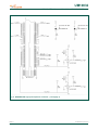
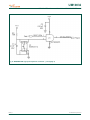
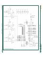
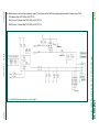
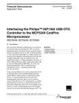
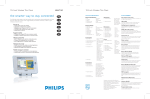
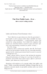
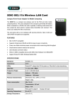
1
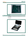
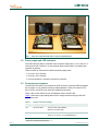
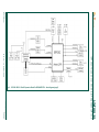
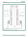
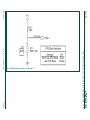
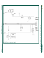
UM10032
ISP1362 OTG add-on eval kit with Intel PXA250/255 IDP rev. 4
Rev. 04 — 12 October 2009
User manual
Document information
Info
Content
Keywords
isp1362; pxa250; pxa25; otg; on-the-go; usb; universal serial bus
Abstract
This document describes the ISP1362 OTG add-on eval kit for Intel
PXA250/255 IDP rev. 04.
UM10032
ISP1362 OTG add-on eval kit with Intel PXA250/255 IDP rev. 4
Revision history
Rev
Date
Description
04
20091012
Rebranded to the ST-Ericsson template.
03
20090203
Rebranded to the ST-NXP Wireless template.
02
20030601
Updated Table 1.
Added PXA255.
01
20030501
First release.
Contact information
For additional information, please visit: http://www.stericsson.com
For document related queries, please send an email to: [email protected]
UM10032_4
User manual
© ST-ERICSSON. All rights reserved.
Rev. 04 — 12 October 2009
2 of 21
UM10032
ISP1362 OTG add-on eval kit with Intel PXA250/255 IDP rev. 4
1. Introduction
The ISP1362 is a single-chip Universal Serial Bus (USB) On-The-Go (OTG) Controller,
Host Controller (HC) and Device Controller (DC).
• The OTG controller is fully compliant with On-The-Go Supplement to the USB 2.0
Specification Rev. 1.0a.
• The host controller is fully compliant with Universal Serial Bus Specification Rev. 2.0;
supporting data transfer at full-speed (12 Mbit/s) and low-speed (1.5 Mbit/s).
• The device controller is also fully compliant with Universal Serial Bus Specification
Rev. 2.0; supporting data transfer at full-speed (12 Mbit/s).
The target applications of the ISP1362 are embedded systems, portable devices, digital
still cameras, and so on. It has a 16-bit data bus for interfacing with a microprocessor
and separate I/O addresses.
The ISP1362 evaluation kit with PXA250/255 is a standalone embedded system
evaluation kit. Using the popular Intel PXA250 or PXA255 (previously known as the
Cotulla) processor, this kit can fully utilize the bandwidth of the ISP1362.
To shorten the development time for customers, ST-Ericsson has partnered with
BSQUARE to bring about an OTG add-on evaluation kit with Intel PXA250/255 IDP.
During the initial partnership, BSQUARE had provided IDP revision 2.0. Over time,
BSQUARE upgraded its IDP to revision 4.0. For more detailed information on the
changes, refer to the BSQUARE document PX2-IDP Spin 2 Revision Status (PX2-IDP Spin 2 RevSts.pdf).
Note: Before you use the Integrated Development Platform (IDP), read Intel PXA250
Applications Processor Integrated Development Platform (linux_user_guide_EUG-00040001B.pdf) User’s Guide from BSQUARE.
Fig 1, Fig 2, Fig 3 and Fig 4 show the ISP1362 OTG add-on card for PXA250/255 IDP.
Fig 1. ISP1362 OTG add-on card for PXA250/255 IDP
UM10032_4
User manual
© ST-ERICSSON. All rights reserved.
Rev. 04 — 12 October 2009
3 of 21
UM10032
ISP1362 OTG add-on eval kit with Intel PXA250/255 IDP rev. 4
Fig 2. Top view of the ISP1362 OTG add-on car d for PXA250/255 IDP
Fig 3. Side view of the ISP1362 OTG add-on card for PXA250/255 IDP
UM10032_4
User manual
© ST-ERICSSON. All rights reserved.
Rev. 04 — 12 October 2009
4 of 21
UM10032
ISP1362 OTG add-on eval kit with Intel PXA250/255 IDP rev. 4
Fig 4. Bottom view of the ISP1362 OTG add-on card for PXA250/255 IDP
2. System requirements
• Two BSQUARE Linux IDP boards (version 2 or later) with the ISP1362 OTG add-on
cards attached.
• One OTG cable.
• A USB speaker.
Fig 5. BSQUARE IDP version 2
UM10032_4
User manual
© ST-ERICSSON. All rights reserved.
Rev. 04 — 12 October 2009
5 of 21
UM10032
ISP1362 OTG add-on eval kit with Intel PXA250/255 IDP rev. 4
Fig 6. BSQUARE IDP version 4
3. Installation
1. Copy the nk.bin file to a CompactFlash (CF) memory unit, and firmly insert the
ISP1362 OTG add-on card for the PXA250/255 IDP into connector J13 on the
BSQUARE IDP board.
2. Insert a PC card adapter with CF into either of the PC card slots in the BSQUARE
IDP.
3. Switch ON the BSQUARE IDP, and wait for the CF memory to be reprogrammed.
4. Eject the PC card to reboot the BSQUARE IDP.
The ISP1362 evaluation kit with PXA250/255 IDP is now ready for testing.
For information on other ways to program the CF unit in BSQUARE IDP, refer to the
BSQUARE document Intel PXA250 Applications Processor Integrated Development
Platform.
3.1 Setting up the Integrated Development Platform (IDP)
1. Boot the PXA250/255 IDP.
2. Follow the instructions according to the operating system installed on the IDP.
Fig 7 shows a setup of the ISP1362 OTG add-on card for PXA250/255 IDP.
Note: To play an MP3 file on an IDP, make sure the file is first uploaded to the IDP
through the Ethernet. For more information on how to upload a file, refer to the
BSQUARE document Intel PXA250 Applications Processor Integrated Development
Platform.
UM10032_4
User manual
© ST-ERICSSON. All rights reserved.
Rev. 04 — 12 October 2009
6 of 21
UM10032
ISP1362 OTG add-on eval kit with Intel PXA250/255 IDP rev. 4
Fig 7. Setup of the ISP1362 OTG add-on card for PXA250/255 IDP
3.2 Power supply and LED indicators
In the ISP1362 OTG add-on evaluation card, the power supply inputs, +3.3 V and +5.0 V,
come from the IDP. Therefore, no other external power supply input or on-board power
regulation is required.
There are LEDs on the board to indicate the power supply status:
• D1 is the +3.3 V indicator.
• D2 is the +5.0 V indicator.
• D3 is the GoodLink1 indicator for the device controller.
3.3 Connectors and jumpers
The ISP1362 OTG add-on card contains an OTG connector (J2) and a USB downstream
port connector (J1) to interface with other USB peripherals. Jumper JP1 sets the OTG
port to OTG or non-OTG mode, while JP2 disables the host port.
There is also a reset switch (S1) for the hardware reset of the ISP1362.
Table 1 shows the jumper settings that must be configured before using the ISP1362
OTG add-on card.
Table 1.
Jumper and switch settings
Jumper
Description
JP1
OTG port select
Setting
Short for OTG mode [default]
Open for non-OTG mode
JP2
Host port enable
Short <1—3> and <2—4> for enabling port 2 [default]
Short <3—5> and <4—6> for disabling port 2
1
GoodLink is a trademark of ST-Ericsson.
UM10032_4
User manual
© ST-ERICSSON. All rights reserved.
Rev. 04 — 12 October 2009
7 of 21
UM10032
ISP1362 OTG add-on eval kit with Intel PXA250/255 IDP rev. 4
Jumper
Description
JP3
ID pin select
Setting
Open (use ID from connector) [default]
Short (force ID to zero)
Fig 8. ISP1362 OTG add-on card on the PXA250/255 IDP
4. ISP1362 bill of materials
Table 2.
Bill of materials
Quantity
Part reference
Description
9
C2, C5, C6, C9, C10, C16,
C17, C21, C22
12
Rating
Manufacturer
Capacitor, SMD MLC, 0.01 μF, ±10% 0.01 μF
50 V NPO/X7R, 0603
50 V
Generic
C7, C8, C13, C14, C15,
C20, C24, C25, C27, C31,
C33, C34
Capacitor, SMD MLC, 0.1μF, ±10%
16 V X7R, 0603
0.1 μF
16 V
Generic
2
C23, C26
Capacitor, SMD MLC, 22 pF, ±10%
50 V NPO/X7R, 0603
22 pF
50 V
Generic
1
C12
Capacitor, SMD MLC, .022 μF, ±10% 0.022 μF
16 V X7R, 0603
16 V
Generic
0
C11
Capacitor, SMD MLC, .022 μF, ±10% 0.022 μF
16 V X7R, 0603
16 V
Generic
4
C18, C19, C28, C29
Capacitor, SMD, NPO/X7R 47 pF,
±10% 50 V 0603
47 pF
50 V
Generic
2
C1, C32
Capacitor SMD, tantalum chip, 4.7
4.7 μF
20 V
AVX
UM10032_4
User manual
Value
© ST-ERICSSON. All rights reserved.
Rev. 04 — 12 October 2009
8 of 21
UM10032
ISP1362 OTG add-on eval kit with Intel PXA250/255 IDP rev. 4
Quantity
Part reference
Description
Value
Rating
Manufacturer
100 μF
16 V
AVX
μF, 16 V, TAJ A-CASE
1
C30
Capacitor SMD, tantalum chip, 100
μF, 16 V, TAJ D-CASE
2
C3, C4
Capacitor SMD, tantalum chip, 47 μF, 47 μF
16 V, TAJ D-CASE
16 V
AVX
1
U6
ISP1362 USB OTG controller
-
-
ST-Ericsson
2
JP1, JP3
Header – 1 x 2 .025SQ PIN .100
centers
-
-
Generic
1
JP2
Header – 2 x 3 .025SQ PIN .100
centers
-
-
Generic
1
J3
High-speed terminal, MIT series, 50
Ω, 152 contact, 0.025 in spacing, 8
mm board spacing
-
-
Samtec
1
J1
USB Type A connector, no panel
grounding ears
-
-
Tyco/Amp
1
J2
Conn, Mini-AB USB, surface mount
-
-
Acon
2
U11, U12
Diode SMD, Dual USB transient
suppressor
-
-
Texas
instruments
2
FB1, FB2
Ferrite bead, SMD, with copper
pattern heat sink
-
2A
muRata
electronics
4
M1, M2, M3, M4
Shunt, single position, .100 center,
black
-
-
Samtec
1
S1
Switch, SMD, momentary, NO,
w/ground tab
-
-
Omron
4
U3, U4, U5, U9
IC SMD single OR gate 5 pin
-
-
Fairchild
1
U1
UHS 2-input AND gate, SC70 5 lead
-
-
Fairchild
2
U7, U10
IC SMD, UHS buffer W/3 state out
NC7SZ125P5 SC70, 5 lead
-
-
Fairchild
2
U2, U8
NC7SZ04P5 single gate inverter
-
-
Fairchild
2
D1, D2
LED SMT 0805 red
-
-
Lumex
1
D3
LED SMT 0805 green
-
-
Lumex
0
R17
Resistor, SMD, spare, 1206
0
-
No mfg-etched
part
4
R9, R10, R19, R20
Resistor, SMD, fixed, film, chip, 22.0
Ω, ±5%, 1/16 W, 0603
22
1/16 W
Generic
5
R3, R4, R5, R13, R22
Resistor, SMD, fixed, film, chip, 10 K, 10 K
±5%, 1/16 W, 0603
1/16 W
Generic
UM10032_4
User manual
© ST-ERICSSON. All rights reserved.
Rev. 04 — 12 October 2009
9 of 21
UM10032
ISP1362 OTG add-on eval kit with Intel PXA250/255 IDP rev. 4
Quantity
Part reference
7
Description
Value
Rating
Manufacturer
R6, R7, R8, R14, R15, R16, Resistor, SMD, fixed, film, chip, 100
R23
K, ±5%, 1/16 W, 0603
100 K
1/16 W
Generic
2
R18, R21
Resistor, SMD, fixed, film, chip, 15.0
K, ±5%, 1/16 W, 0603
15 K
1/16 W
Generic
2
R1, R24
Resistor, SMD, fixed, film, chip, 470
Ω, ±5%, 1/16 W, 0603
470
1/16 W
Generic
2
R11, R12
Resistor, SMD, fixed, film, chip, 4.70
K, ±5%, 1/16 W, 0603
4.7 K
1/16 W
Generic
1
R2
Resistor, SMD, fixed, film, chip, 680
Ω, ±5%, 1/16 W, 0603
680
1/16 W
Generic
2
Q1, Q2
MOSFET, P-channel, 30 V Vds
-
-
Fairchild
1
Y1
12 MHZ, SM, crystal
-
-
Citizen
1
PCB, ST-Ericsson ISP1362 USB On-The-Go expansion board for BSQUARE IDPs
5. ISP1362 OTG add-on evaluation card schematics
UM10032_4
User manual
© ST-ERICSSON. All rights reserved.
Rev. 04 — 12 October 2009
10 of 21
UM10032_4
User manual
UM10032
11 of 21
© ST-ERICSSON. All rights reserved.
ISP1362 OTG add-on eval kit with Intel PXA250/255 IDP rev. 4
Rev. 04 — 12 October 2009
Fig 9. ISP1362 USB On-The-Go Expansion Board For BSQUARE IDP's - block diagram (page 2)
UM10032
ISP1362 OTG add-on eval kit with Intel PXA250/255 IDP rev. 4
Fig 10. BSQUARE IDP high-speed expansion connector – part 1 (page 3)
UM10032_4
User manual
© ST-ERICSSON. All rights reserved.
Rev. 04 — 12 October 2009
12 of 21
UM10032
ISP1362 OTG add-on eval kit with Intel PXA250/255 IDP rev. 4
Fig 11. BSQUARE IDP high-speed expansion connector – part 2 (page 3)
UM10032_4
User manual
© ST-ERICSSON. All rights reserved.
Rev. 04 — 12 October 2009
13 of 21
UM10032
ISP1362 OTG add-on eval kit with Intel PXA250/255 IDP rev. 4
Fig 12. BSQUARE IDP high-speed expansion connector – part 3 (page 3)
UM10032_4
User manual
© ST-ERICSSON. All rights reserved.
Rev. 04 — 12 October 2009
14 of 21
UM10032_4
User manual
UM10032
ISP1362 OTG add-on eval kit with Intel PXA250/255 IDP rev. 4
Rev. 04 — 12 October 2009
15 of 21
© ST-ERICSSON. All rights reserved.
Fig 13. ISP1362 USB OTG controller (page 4)
UM10032_4
User manual
For DMA accesses, use the following address ranges. This will generate the DMA Acknowledge signals needed. Processor uses CS2#.
PIO Address Map: 0000 0000h to 00FF FFFFh.
DMA Channel 0 Address Map: 0200 0000h to 02FF FFFFh.
DMA Channel 1 Address Map: 0100 0000h to 01FF FFFFh.
UM10032
16 of 21
© ST-ERICSSON. All rights reserved.
ISP1362 OTG add-on eval kit with Intel PXA250/255 IDP rev. 4
Rev. 04 — 12 October 2009
Fig 14. USB OTG and host connectors – part 1 (page 5)
UM10032_4
User manual
UM10032
17 of 21
© ST-ERICSSON. All rights reserved.
ISP1362 OTG add-on eval kit with Intel PXA250/255 IDP rev. 4
Rev. 04 — 12 October 2009
Fig 15. USB OTG and host connectors – part 2 (page 5)
UM10032_4
User manual
UM10032
18 of 21
© ST-ERICSSON. All rights reserved.
ISP1362 OTG add-on eval kit with Intel PXA250/255 IDP rev. 4
Rev. 04 — 12 October 2009
Fig 16. USB OTG and host connectors part 3 (page 5)
UM10032
ISP1362 OTG add-on eval kit with Intel PXA250/255 IDP rev. 4
6. References
[1]
ISP1362 Single-chip USB On-The-Go controller data sheet
[2]
ISP1362 Linux Stack user manual
[3]
Universal Serial Bus Specification Rev. 2.0
[4]
On-The-Go Supplement to the USB 2.0 Specification Rev. 1.0a
[5]
Intel PXA250 Applications Processor Integrated Development Platform User’s
Guide from BSQUARE (linux_user_guide_EUG-0004-0001B.pdf)
UM10032_4
User manual
© ST-ERICSSON. All rights reserved.
Rev. 04 — 12 October 2009
19 of 21
UM10032
ISP1362 OTG add-on eval kit with Intel PXA250/255 IDP rev. 4
7. Legal information
Please Read Carefully:
The contents of this document are subject to change without prior notice. ST-Ericsson
makes no representation or warranty of any nature whatsoever (neither expressed nor
implied) with respect to the matters addressed in this document, including but not limited to
warranties of merchantability or fitness for a particular purpose, interpretability or
interoperability or, against infringement of third party intellectual property rights, and in no
event shall ST-Ericsson be liable to any party for any direct, indirect, incidental and or
consequential damages and or loss whatsoever (including but not limited to monetary losses
or loss of data), that might arise from the use of this document or the information in it.
ST-Ericsson and the ST-Ericsson logo are trademarks of the ST-Ericsson group of
companies or used under a license from STMicroelectronics NV or Telefonaktiebolaget LM
Ericsson.
All other names are the property of their respective owners.
© ST-Ericsson, 2009 - All rights reserved
Contact information at www.stericsson.com under Contacts
www.stericsson.com
UM10032_4
User manual
© ST-ERICSSON. All rights reserved.
Rev. 04 — 12 October 2009
20 of 21
UM10032
ISP1362 OTG add-on eval kit with Intel PXA250/255 IDP rev. 4
8. Contents
1.
2.
3.
3.1
3.2
3.3
4.
5.
6.
7.
8.
Introduction ......................................................... 3
System requirements .......................................... 5
Installation ........................................................... 6
Setting up the Integrated Development Platform
(IDP) ................................................................... 6
Power supply and LED indicators ...................... 7
Connectors and jumpers .................................... 7
ISP1362 bill of materials ..................................... 8
ISP1362 OTG add-on evaluation card
schematics ......................................................... 10
References ......................................................... 19
Legal information .............................................. 20
Contents ............................................................. 21
© ST- Ericsson 2009. All rights reserved.
For more information, please visit: http://www.stericsson.com
For document related queries, email to: [email protected]
Date of release: 12 October 2009
Document identifier: UM10032_4