Transcript
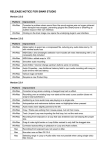
SERVICE ADVISORY
Subject: When unit is connected as stated in the manual, loud
turn-on and turn-off pops are noticed.
Brand: Rockford Fosgate - 3Sixty Signal Proccessor
Bulletin No.: SrvAdvise-05
Date Issued: April, 2006
• BULLETIN NOTES
Use the following instructions instead of those in the Installation and Operation Manual to connect your unit to prevent audible
“poping” noises during turn-on and turn-off.
WIRING THE SYSTEM
CAUTION: If you do not feel comfortable with wiring your new unit, please see your local Authorized Rockford
Fosgate Dealer for installation.
CAUTION: Before installation, disconnect the battery negative (-) terminal to prevent damage to the unit, fire and/or
possible injury.
CAUTION: Avoid running power wires near the low level input cables, antenna, power leads, sensitive equipment or
harnesses.The power wires carry substantial current and could
induce noise into the audio system.
Connector
Power Connection
1. Plan the wire routing. Keep RCA cables close together but isolated from power
Ground
cables and any high power auto accessories, especially electric motors.This is done to
prevent coupling the noise from radiated electrical fields into the audio signal.When
feeding the wires through the firewall or any metal barrier, protect them with plastic
or rubber grommets to prevent short circuits. Leave the wires long at this point to
adjust for a precise fit at a later time.
Remote
Strip 1/4"
2. Prepare the RED wire (power cable) for attachment to the power connector by
(0.25)
stripping 1/4" (6.4mm) of insulation from the end of the wire. Insert the bared wire
Power B+
into the B+ terminal and tighten the setscrew to secure the cable in place.
(6.4mm)
3. Connect the RED (B+) wire to a constant 12 volt DC source.
NOTE: If you are connecting directly to the battery, ensure the wire is equipped with a fuse (2 amp).
4. Prepare the BLACK wire (ground cable) for attachment to the power connector by stripping 1/4" (6.4mm) of insulation from the end of
the wire. Insert the bare wire into the GND terminal and tighten the setscrew to secure the cable in place. Prepare the chassis ground
by scraping any paint from the metal surface and thoroughly clean the area of all dirt and grease. Strip the other end of the wire and
attach a ring connector. Fasten the cable to the chassis using a non-anodized screw and a star washer.
NOTE: Keep the length of the BLACK wire (Ground) as short as possible.
NOTE: The REM connection can be used as either an input (turning on and off the 3Sixty unit) or as an output (used to turn on or off
an amplifier or other accessory). If the source unit provides a remote turn on, it is recommended that the REM be used as an
input. If a remote lead is not available, the 3Sixty will turn on and off via signal sense circuitry.
5. Prepare the REM (remote) wire for for attachment to the power connector by stripping 1/4" (6.4mm) of insulation from the end of the
wire. Insert the bared wire into the REM terminal and tighten the setscrew to secure the wire in place.
Used as an input: Connect the other end of the REM wire to a switched 12 volt positive source.The switched voltage is usually taken
from the source unit's remote amp on lead.
Used as an output: You will need to contact customer service for proper procedure to reconfigure the unit to set the REM as an
output.
6. Securely mount the 3Sixty unit to the vehicle and insert the power connector into the 3Sixty.
Use the Installation and Operation Manual for the rest of unit connections.
• REPAIR PROCEDURE
See Above
• WARRANTY INFORMATION
N/A
04/06 B.M.
SrvAdvise-05