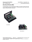
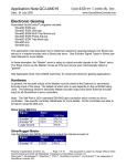
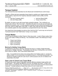
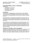
1
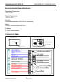
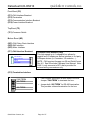
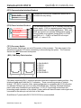
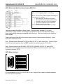
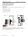
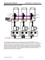
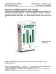
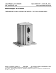
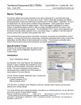
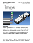
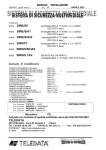
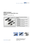
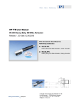
QuickSilver Controls, Inc. Datasheet:QCI-DS016 Date: 5 November 2008 www.QuickSilverControls.com SilverDust D2-IGC Datasheet Servo controller/driver for QuickSilver’s NEMA 11, 17 and 23 frame servomotors. These SilverDust controllers have a compact DIN mount designed to save cabinet space and come standard with the CANopen® bus. They are great for multi-axis systems. QCI-D2-IGC Property of QuickSilver Controls, Inc. Page 1 of 17 This document is subject to change without notice. QuickControl® and QCI® are Registered Trademarks of QuickSilver Controls, Inc. SilverLode™, SilverNugget™, SilverDust™, PVIA™, QuickSilver Controls™, and AntiHunt™ are trademarks of QuickSilver Controls, Inc.. QuickSilver Controls, Inc. Datasheet:QCI-DS016 System Overview Point-to-Point Moves • Relative or Absolute • Velocity or Time Based • S-Curve Advanced Motion Profile Moves • Profile Move Commands • Register Based o Position/Accel/Decel/Vel o Modify On-the-Fly Multi-Axis Linear Interpolation • XYZ Coords Contained in Text File • CANopen® used for local bus • 1000+ Points Stored In NV Memory Built-In Voltage Clamp • Regenerative Braking Resistor Input/Output • 7 TTL Digital I/O o Use for QCI-BO-B52 24V I/O • 4 Analog Inputs (Joystick) • Analog Output Option • Programmable Limit Switch (PLS) • Secondary Encoder In Program and Data Storage • 32K Non-Volatile Memory: • 2000-3000 Program Lines • User Data Examples o CAM Tables o Motion Profiles o Lookup Tables Electronic Slip Clutch/Brake • Variable Torque • Wind/Unwind Applications Anti-Hunt™ • Optionally use Open Loop While Holding • No Servo Dither While At Rest QuickSilver Controls, Inc. Page 2 of 17 Electronic Gearing/Camming • Follow Encoder (A/B Quadrature) or Step and Direction • Dynamic Gear Ratios o Integer Ratios 32767:1 to 1:32767 o Decimal Ratios to 7 Places • Electronic Cam o Import Tables From Text File o Over 2500 Points o Multiple Tables Communications • RS-485/RS-232 @ 230K Baud • ASCII,Binary,Modbus®,DMX512 • CANopen® • Host Control While Servo in Motion Programming Language • Easy, Menu Driven Interface • Command Parameter Prompts • No Syntax Errors • User Namable I/O and Registers Advance PVIA™ Servo Loop • 100:1 Inertial Mismatch • Direct Drive Oversized Inertial Loads o Flywheels/Belt Drives o Typically Without Gearheads • More Stable Than PID Digital 4 Quadrant Vector Drive • DSP Driven for Reduced Noise Multi-Task/Multi-Thread Compatible with QCI Motor/Encoders • NEMA 11 Frame o 4000 Counts/Rev Encoder o Up To 9 oz-in (continuous) • NEMA 17 Frame o 8000 Counts/Rev Encoder o Up To 43 oz-in (continuous) o IP50 or IP65 • NEMA 23 Frame o 8000 Counts/Rev Encoder o Up To 300 oz-in (continuous) o IP50 or IP65 UL, CUL, CE QuickSilver Controls, Inc. Datasheet:QCI-DS016 Electrical Specifications Input Power Voltage +12 VDC to +48 VDC, regulated. The controller must be initialized for the actual operating voltage using Initialization Wizard. Over-Voltage Protection Voltages exceeding +55 VDC will permanently damage the controller/driver electronics. All controllers include an onboard clamp circuit and braking resistor to dissipate excess current developed during re-generative braking (stopping). Reverse Polarity Protection Reverse polarity protection is provided. Note, however, if the power supply is not floating, connecting the V+ input to Ground will cause this potential to be present at the communications and I/O lines, which may damage these lines or that to which they are connected. Input Current 4 Amps maximum for any input voltage, +12 VDC to +48 VDC. Output Power Output/Driver Current Amps Per Phase: 3.5 Continuous/ 4.5 Peak with adequate heat dissipation (heat sink). Maximum Output Power 150 Watts continuous power with adequate heat dissipation. Encoder Interface From Motor Encoder: Quadrature (Differential Ended)) From External (Secondary) Encoder: Quadrature (Single Ended) Note, CANopen® encoders may also be used through the CANopen communication bus. CANopen® and CiA® are registered community trade marks of CAN in Automation e.V. QuickSilver Controls, Inc. Page 3 of 17 QuickSilver Controls, Inc. Datasheet:QCI-DS016 Inputs & Outputs Standard I/O 7 I/O (1-7) Digital Inputs 0 to +3.3 VDC. LVTTL level compatible. Effective internal 200K ohm impedance to +3.3 V. Digital Output Voltage 0 / +3.3 VDC. Digital Output Current Sinking or Sourcing I/O 1, 4, 5, 7 outputs 4 mA MAX I/O 2 and 3 outputs 2 mA MAX I/O 6 outputs 8 mA MAX I/O Over-Voltage Protection An over-voltage limiter protects each standard I/O line up to 30 volts. Applying voltages greater than 30 volts will permanently damage the I/O. Analog Inputs 0 to +3.3 VDC input signal range. 10 bit ADC resolution (single). 11 bit ADC resolution (differential). Analog inputs 1 to 4 are mapped to share digital I/O lines 4 to 7. Each input has an effective internal 200K ohm impedance to +3.3 VDC. Analog signals are read every servo cycle (120 µsec.) and the converted analog data is processed through a 5 ms filter to reduce noise & transients. Analog Output Available on I/O 2, but requires Basic Breakout w/ Analog Output (QCI-BO-B1A). See technical document QCI-TD048. Driver Enable Inputs 10-48 Volts optically isolated differential inputs QuickSilver Controls, Inc. Page 4 of 17 QuickSilver Controls, Inc. Datasheet:QCI-DS016 Communications Hardware Interfaces RS-232, RS-232 multi-drop, RS-485 multi-drop (software selectable) Protocols 8-bit ASCII, 9-bit binary, or Modbus RTU. Hardware Configuration Settings Available Baud Rates: 2400, 4800, 9600, 19.2k, 28.8k, 57.6k, 115.2k or 230.4k Data Bits: 8 Stop Bits: 1.5 or 2 Parity Bit: None Controller Area Network (CAN) Software Required: Firmware Rev 29 (QuickControl Rev 4.5) See CANopen User Manual for hardware and software details. QuickSilver Controls, Inc. Page 5 of 17 QuickSilver Controls, Inc. Datasheet:QCI-DS016 Mechanical Specification QCI-D2-IGC 1.90 48.2 mm 3.12 79.1 mm 2.56 65.0 mm .56 14.2 mm 1.45 36.8 mm .19 4.7 mm .45 11.4 mm 4.60 116.7 mm 4.78 121.5 mm .08 2.0 mm .125 3.18 mm .08 2.0 mm Note: See our website for 2D drawings and 3D models. QuickSilver Controls, Inc. Page 6 of 17 QuickSilver Controls, Inc. Datasheet:QCI-DS016 Environmental Specifications Operational Temperature -10 C to +80 C Storage Temperature - 40 C to +85 C Humidity Continuous specification is 95% RH non-condensing. Shock Limitation is approximately 50g/11ms. IP Rating IP20 with cables attached. Connector Data Top Panel (TP) Bottom Panel (BP) CAN CAN CAN Daisy Chain RJ11 (BP1) ON PROC. OFF www.QuickSilverControls.com MOTOR/ENC SMI Interface (BP2) Motor Interface (BP3) Processor Switch (TP1) V+ L H VB/Tx A/Rx Gnd V+Pr V+ V- CAN SHIELD CAN 12-24 VDC CAN L CAN H CAN 0 VDC CAN Breakout (FP1) CAN TERM 485 TERM RS232TX - RS485B RS232RX - RS485A Comm Ground 485 TERM Vclamp + DRIVER ENABLE + DRIVER ENABLE V+ Proccessor V+ V- or PGND QuickSilver Controls, Inc. COMM/IO SMI Termination (FP2) Serial Comm (FP3) Power (FP4) Page 7 of 17 QuickSilver Controls, Inc. Datasheet:QCI-DS016 Front Panel (FP) (FP1) CAN Interface Breakout (FP2) Termination (FP3) Communication Interface Breakout (FP4) Power Interface Breakout Top Panel (TP) (TP1) Processor Switch Bottom Panel (BP) (BP1) CAN Daisy Chain Interface (BP2) SMI Interface (BP3) Motor Interface (FP1) CAN Interface Breakout V+ L H V- CAN SHIELD CAN 12-24 VDC CAN L CAN H CAN 0 VDC Controller Area Network (CAN) This high-speed up to 1-megabit/s bus allows for register and I/O sharing as well as interface to 3rd party CANopen devices (i.e. encoders, I/O modules,…). NOTE: CAN requires firmware rev 29 and QuickControl Rev 4.5. See SilverLode CANopen User Manual. Note: CAN V+ only connects to BP1 and is provided for external wiring convenience only. (FP2) Termination Interface CAN TERM 485 TERM 485 TERM QuickSilver Controls, Inc. • CAN requires termination at both ends of the bus. Jumper “CAN TERM” to terminate the bus. • Jumper both “485 TERM” for RS-485 termination. This provides a biased termination for the bus. Page 8 of 17 QuickSilver Controls, Inc. Datasheet:QCI-DS016 (FP3) Communication Interface Breakout B/Tx A/Rx Standard RS-232/RS-485 connections broken out to terminals for easy wiring. RS232TX - RS485B RS232RX - RS485A COMM GND Gnd (FP4) Power Interface Breakout V+Pr V+ V- The two main items are V+ & V-, normally from the main power supply. V+Pr is a separate power input to keep the processor alive for certain applications. ENA+ and ENA- are inputs to an optically isolated drive enable. If Driver Enable is not needed, jumper ENA+ to CLMP and ENA- to V-. CLMP is a fused 500 mA output. CLMP = V+ minus 0.3V. V+ CLAMPED OUT DRIVER ENABLE + DRIVER ENABLE V+ Proccessor V+ V- or PGND (TP1) Processor Switch The Processor Switch turns on and off the power to the processor. The main power to the SilverDust should be OFF before connecting or disconnecting the system. The Processor Switch does NOT disconnect main power. (BP1) CAN Daisy Chain Interface Pinout 1 CAN SHIELD 2 CAN V+ 3 CAN H 4 CAN L 5 CAN GND 6 CAN SHIELD 1 6 1 6 CAN daisy chain using RJ11 connector provides clean and inexpensive cabling solution. Any telephone cable works with the RJ11 connector. These connections require a “straight through” UTP RJ12 connector. Note, signal configuration is compatible with RJ10 connector for standard CANopen pin-out if not using CAN Shield lines. Warning: Standard telephone patch cords swap connections on signal pairs (1-6,2-5,3-4) reversing connections and preventing proper operation of the system. Proper cables will have the same color signal wire connected to the same pin on both ends of the cable. QuickSilver’s 6” patch cable QCI-C-RJ12-RJ12-A is recommended. QuickSilver Controls, Inc. Page 9 of 17 QuickSilver Controls, Inc. Datasheet:QCI-DS016 (BP2) SilverLode Multi-function Interface (SMI) Port These signals provide power, communications and 3.3v IO signals (digital and analog). NOTE: QCI has many modules capable of breaking out these signals. For example: • Basic Breakouts (QCI-BO-B, QCI-BO-B1) • Basic Breakout w/ Analog Out (QCI-BO-B1A) • Breakout w/ 24V IO -5in 2out (QCI-BO-B52) • 24V Optical I/O Module (QCI-OPTMC-24)* *Requires QCI-EC-SMI cable See technical documents on our website for details. This port provides QuickSilver’s basic Power, Communication, standard I/O for easy connectivity in large systems. The SMI port is standard on all our controllers which helps make new products backward compatible with older ones. See above sections for details on these signals. Power inputs are diode OR’ed into power inputs from the Power Interface Breakout. Apply power from either port is OK. Note: Encoder Inputs described in SSI Port uses I/O # 4, 5, and 6 listed here. If these I/O are used for electronic gearing, they are NOT available for general purpose I/O function. Note: Communication lines RS-485A / RS-232 RX, RS-485B / RS-232 TX, and LOGIC GROUND are all internally connected between the SMI port and the respective pins on the front side connector (FP4). (BP3) Motor Interface 15 14 13 12 11 10 9 8 7 6 5 4 3 2 1 1 2 3 4 5 6 7 8 9 10 11 12 13 14 15 Motor B+ Chassis Ground + 5V Encoder Power Encoder A Encoder B Motor A + Motor B Encoder Z + Encoder A + Encoder Z Motor A Chassis Ground Encoder B+ Encoder Ground Motor Memory Access QCI recommends our QCI-C-D15P-D15S-nn (nn = length in feet) cable to interface between the motor and the controller. QuickSilver Controls, Inc. Page 10 of 17 QuickSilver Controls, Inc. Datasheet:QCI-DS016 The Motor I/F Breakout (QCI-BO-M1) can be used to breakout these signals. See Technical Document QCI-TD057 "Motor I/F Breakout - QCI-BO-M1". Recommended Components SilverDust IGC Start-Up Kit (QCI-SKB-D2-IGC) For first time users, QCI recommends purchasing the QCI-SKB-D2-IGC Start-Up Kit which includes: • SilverDust D2 (QCI-D2-IGC) & Datasheet (QCI-DS016) • QuickControl Software CD User Manual & Command Reference (QCI-SLM) • Communication Cable (QCI-C-D9M9F-6) • 4’ DB15HD Motor I/F Cable (QCI-C-D15P-D15S-4) • DIN Rail Bracket (QCI-DIN1) • Basic Breakout (QCI-BO-B) • Start-Up Kit Setup Instructions (QCI-TD060) With this Start-Up kit, a power supply, and a motor/encoder, you will have everything you need to get started. See technical document QCI-TD060 on our website for details. The system detailed below uses the QCI-SKB-D2-IGC. QuickSilver Controls, Inc. Page 11 of 17 QuickSilver Controls, Inc. Datasheet:QCI-DS016 SilverDust IGC System CPU POWER ON QCI-D2-IGC V+ L H V- JUMPERS CAN TERM 485 TERM B/Tx A/Rx 485 TERM _ + Gnd QCI-C-D9M9F-6 V+Pr V+ V- QCI-BO-B 17/23 FRAME MOTOR/ENCODER QCI-D15P-D15S-nn 1. Controller/Driver Standard controller/driver is a QCI-D2-IGC with CAN. 2. Motor I/F Cable For standard systems, this D-sub type cable goes between the motor and the controller. The generic part number is QCI-C-D15P-D15S-nn. Replace the last two digits “nn” with length of cable in feet (i.e. –10 for 10 feet). For IP65 system, a special IP65 cable goes in between the motor and the controller. The motors and cables are IP65, but not the controller/driver. The generic part number is QCI-C-D15P-T14S-nn. Replace the last two digits “nn” with length of cable in feet (i.e. –10 for 10 feet). 3. Motor The SilverDust D2 is capable of driving any A 17 or 23 I-Grade motor/encoder. See the following datasheets for more information: QuickSilver Controls, Inc. Page 12 of 17 QuickSilver Controls, Inc. Datasheet:QCI-DS016 QCI-DS007: QCI-DS008: QCI-DS002: QCI-DS001: NEMA 17 I-Grade Motor/Encoder NEMA 23 I-Grade Motor/Encoder NEMA 17 IP65 Motor/Encoder NEMA 23 IP65 Motor/Encoder 4. Power Supply Power supply selection is motor dependent, but the following will work with all the 17 and 23 frame motors. S-210-48 (48V, 4.4A, 210 Watt) 5. Breakout Module (optional) Optional equipment QCI-BO-B Pluggable terminal blocks (provided). CAN CAN terminate at the end only RS-485 terminate at the end only Do not jumper for RS-232 _ COMM/IO SMI QCI-D15P-D15S-nn MOTOR/ENC CAN + The QCI-BO-B from QuickSilver provides inexpensive way to breakout all the TTL I/O. Another version is the QCI-BO-B52, which allows 5 isolated 24Volts inputs and 2 Open Drain outputs. See QCI-TD046 for more details. QuickSilver Controls, Inc. Page 13 of 17 QuickSilver Controls, Inc. Datasheet:QCI-DS016 6. Din Rail Mount (Optional) The DIN Rail Bracket (QCI-DIN) is an optional kit for din mountable applications. See below. QCI-DIN1 QCI-DIN1 8-32 Screws (2) Provided 1.90 [48.26 mm] 1.78 [45.10 mm] 0.37 [9.32 mm] QuickSilver Controls, Inc. 1.82 [46.13 mm] Page 14 of 17 QuickSilver Controls, Inc. Datasheet:QCI-DS016 Multi-Axis Setup Serial and CAN CAN terminate at the end only CAN terminate at the end only Serial Bus RS485 terminate at the end only RS-485 terminate at the end only QCI-D15P-D15S-nn QCI-D15P-D15S-nn + QCI-D15P-D15S-nn _ Serial & CAN QCI-C-RJ12-RJ12-A This configuration provides communications between an external PC/HMI/PLC via serial communications. The 485 terminations are shown jumpered for 485 operation. These jumpers should be removed for multi-drop RS-232 operation. The serial port is used to command and monitor the individual units. The CAN bus provides a CANopen link between the multiple axis. This may be used to coordinate axes and to share data and/or IO; the axes may be configured as peer-to-peer or master-slave, or a mix as desired. The CAN bus termination is shown jumpered only at both ends of the CAN bus. QuickSilver Controls, Inc. Page 15 of 17 QuickSilver Controls, Inc. Datasheet:QCI-DS016 CANopen Networks True real-time servo data sent and received in a multi-axis network must be deterministic. QuickSilver CANopen provides the real-time data transmission capabilities to the network. CANopen uses an arbitration method to send and receive messages instead of collision detection. Each time data is sent, all units having data to send start by sending their message Identifier information, while monitoring to see if their message is the highest priority message being asserted. If a higher priority message is detected, the unit with the lower priority message stops transmitting until the bus is not busy. This is done without disrupting the highest priority message. The user is able to select the message priority, and therefore the order in which the messages will transverse the bus. As long as the user takes care to not overload the bus, the messages will be delivered in a timely manner. QuickSilver Controls, Inc. Page 16 of 17 QuickSilver Controls, Inc. Datasheet:QCI-DS016 Part Number SilverDust™ IGC Controller/Driver DRIVER CONTROLLER QCI-D2 - 3.5 Amp • For 23 Frame and Smaller • 3.5 Amps per Phase Continuous* • 4.5 Amp Peak • 4A@12V-48V IGC– SilverDust D2 IGC • 7 TTL Inputs or Outputs (use QCI-BO-B52 for 24V I/O) • 4 Analog Inputs (Joystick) • Analog Output Option (use QCI-BO-B1A) • RS-232 or RS-485 • ASCII, Binary, Modbus® • CANopen • Voltage Clamp And Resistor • Drive Enable • DB15HD (pin): SMI Port • DB15HD (socket): Motor I/F including motor power and encoder * Depending on heat sink (25C ambient). QCI-D2 OPTIONS Blank – Standard • DIN compatible D – DMX512 For multiple options, list fields in alphabetical order To create a part number, choose one from each column above. For a SilverDust IGC with DMX512 IGC D This selection creates the part number: QCI-D2-IGC-D Contact Information QuickSilver Controls, Inc. 580 E. Arrow Hwy, #E San Dimas, CA 91773 (909) 447-7417 or (888) 660-3801 (909) 447-7410 FAX www.QuickSilverControls.com QuickSilver Controls, Inc. Page 17 of 17