1
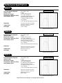
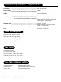
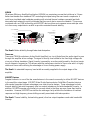
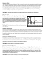
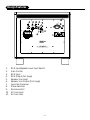
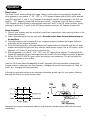
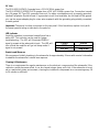
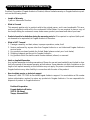
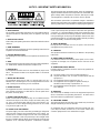
H O M E
P O I N T
T H E A T E R
Z E R O
S E R I E S
F A 1 0 . 0
F A 1 2 . 0
F A 1 5 . 0
A
M
P
L
I
F
I
E
D
O W N E R ’ S
S
U
B
W
O
O
F
E
R
S
M A N U A L
A division of
A U D I O
Rockford Corporation
Declaration of Conformity
Application of Council Directive:
73/23/EEC (Low Voltage Directive)
89/336/EEC (EMC Directive)
Standard(s) to which Conformity is Declared:
EN55103-1
EN55103-2
Manufacturer’s Name:
EN60065
Fosgate Audionics
Manufacturer’s Address:
546 South Rockford Drive, Tempe, Arizona 85281
Importer’s Name:
Importer’s Address:
Type of Equipment: Amplified Subwoofer
Model No:
FA10.0
Year of Manufacturing:
FA12.0
1999
2000
FA15.0
2001
2002
2003
Serial Number:
I, the undersigned, hereby declare that the equipment specified above conforms
to the above Directive(s) and Standard(s)
Place: Fosgate Audionics
Date:
12/01/98
James C. Strickland, VP Engineering
Performance Specifications
FA10.0
Free Field Frequency Response
Sub-Sonic Filter
Peak Acoustic Output
Total Harmonic Distortion (THD)
Low Frequency Driver
27Hz-100Hz, ±2dB
@ 18hz
>112dB (w/music @ 2m)
<3%, 30Hz (90dB @ 2m)
10”(254mm) Cellulose Fibre Cone
Santoprene Rubber Surround
2” (51mm) 4-Layer Voice Coil
30 oz. Magnet
1.0ft3 (28 Liter) Bass Reflex Down Firing
Dimensions
14.75”(H) x 16.0”(W) x 17.50”(D)
(37.46cm x 40.64cm x 40.64cm)
Black Ebony Ash Vinyl
51 lbs. (23.2kg)
Cabinet Finish
Net Weight
Frequency Response
Frequency Response @ 2m*
FA12.0
Free Field Frequency Response
Sub-Sonic Filter
Peak Acoustic Output
Total Harmonic Distortion (THD)
Low Frequency Driver
25Hz-100Hz, ±2dB
@ 18hz
>115dB (w/music @ 2m)
<3%, 25Hz (90dB @ 2m)
12” (305mm) Cellulose Fibre Cone
Santoprene Rubber Surround
2.5” (63.5mm) 4-Layer Voice Coil
102 oz. Magnet
1.8ft3 (50.4Liter) Bass Reflex Down Firing
Dimensions
16.75”(H) x 18.50”(W) x 19.50”(D)
(46.35cm x 49.53cm x 49.21cm)
Black Ebony Ash Vinyl
74 lbs. (33.6kg)
Cabinet Finish
Net Weight
Frequency Response
Frequency Response @ 2m*
FA15.0
Free Field Frequency Response
Sub-Sonic Filter
Peak Acoustic Output
Total Harmonic Distortion (THD)
Low Frequency Driver
22Hz-100Hz, ±2dB
@ 18hz
>118dB (w/music @ 2m)
<3%, 22Hz (90dB @ 2m)
15” (381mm) Cellulose Fibre Cone
Santoprene Rubber Surround
2.5” (63.5mm) 4-Layer Voice Coil
153 oz. Magnet
2.5ft3 (70 Liter) Bass Reflex Down Firing
Dimensions
18.75”(H) x 20.0”(W) x 21.0”(D)
(46.35cm x 49.53cm x 49.21cm)
Black Ebony Ash Vinyl
88 lbs. (40kg)
Cabinet Finish
Net Weight
Frequency Response
Frequency Response @ 2m*
Specifications are subject to change without notice.
–i–
Performance Specifications - Amplifier Section
Power Rating
200W RMS @ 4 ohms
Signal-to-Noise
>100dB
CMRR
>70dB typical @ 60Hz
Input Impedance
47kΩ per phase balanced, 47kΩ unbalanced
Input Sensitivity Range
RCA Input: 160mV to 5V RMS
Speaker Input: 50mV to 45W (receivers that
drive nominal 8Ω speaker loads)
Maximum Input
RCA Input: 10V RMS
Speaker Input: 180W (receivers that drive
nominal 8Ω speaker loads)
Gain
+45dB max. to +15dB min.
Power Consumption
Idle Power: 11W / 150mA @ 120 VAC
Idle Power: 11W / 90mA @ 230 VAC
Normal Operation: 66W / 380mA @ 230VAC
Full Power: 330W / 3.3A @ 120VAC
Full Power: 315W / 1.7mA @ 230VAC
Rear Panel
Unbalanced RCA Inputs
Gain Control (30dB range)
Low Pass Crossover (variable 40Hz~140Hz)
Phase DIP Switches (0°, -90°, -180°, -270°)
Low -Pass Crossover Section
Crossover Frequency
Variable from 40Hz~140Hz
Crossover Slope
24dB/octave (4th order) Linkwitz-Riley
Subsonic Filter
12dB/octave (-3dB @ 18Hz)
Specifications are subject to change without notice.
– ii –
Table of Contents
PERFORMANCE SPECIFICATIONS
Frequency Response Graphs …………………………………………………………………………… i
INTRODUCTION ……………………………………………………………………………………………… 1
TECHNICAL DESIGN FEATURES ……………………………………………………………………………… 1
DESIGN FEATURES ……………………………………………………………………………………………… 4
INSTALLATION
Location …………………………………………………………………………………………………
Typical Studio Installations ……………………………………………………………………………
Home Theater Installations ……………………………………………………………………………
Input Switch ……………………………………………………………………………………………
5
5
5
6
OPERATION
Auto Turn-On/Sleep Mode …………………………………………………………………………… 8
Input Sensitivity ………………………………………………………………………………………… 8
Low-Pass Crossover …………………………………………………………………………………… 8
Phase Control …………………………………………………………………………………………… 9
Set-up Procedure ……………………………………………………………………………………… 9
AC Line ………………………………………………………………………………………………… 10
LED Indicator ………………………………………………………………………………………… 10
Break-In and Warm Up ……………………………………………………………………………… 10
Cleaning and Maintenance…………………………………………………………………………… 10
SERVICE POLICY &LIMITED WARRANTY ………………………………………………………………… 11
SAFETY PRECAUTIONS ……………………………………………………………………………………… 12
– iii –
Introduction
Thank you and congratulations on your purchase of the Point Zero series of Subwoofer, from the
world's finest brand in professional audio equipment.
The Point Zero series is comprised of three modules; the FA10.0, FA12.0, and FA15.0. The FA10.0 is
an amplified 10" subwoofer. The FA12.0 is an amplified 12" subwoofer and the FA15.0 is an amplified 15" subwoofer. All Point Zero series are designed and engineered for Home Theater Systems
and high performance home audio applications.
For ease of use, this manual is organized into two main sections: Installation and Operation.
"Installation" covers the set-up of your new Fosgate Audionics equipment to the system. "Operation"
covers the controls and how to use them for optimum performance.
Technical Design Features
The FA10.0, FA12.0, and FA15.0 monitors utilize a specially designed amplifier featuring our innovative Trans•ana circuitry. This topology, with its unique input-to-output configuration (derived from
our patented Trans•nova circuit), employs power gain in the MOSFET output stage that result in
superior sound quality.
The amplifier features an auto turn-on/off circuit that eliminates the need for a conventional power
switch. Input signals can be fed into the amplifier via Un-Balanced RCA jacks or Speaker level input
jacks. Each pair of inputs is combined into a mono-summed signal before being fed into a 4th order
Linkwitz-Riley low-pass crossover, adjustable from 40Hz~140Hz. If selected, the signal is then fed
into the Phase Control that allows the phase of the signal to be adjusted at 90˚, 180˚, or 270˚ increments.
The FA10.0 is a 10” (254mm) low frequency transducer that features a 2” (51mm) voice coil and is
driven by a 30 oz. magnet. The FA12.0 is a 12” (305mm) low frequency transducer that features a
2.5” (63.5mm) voice coil and is driven by a 102 oz. magnet. The FA15.0 is a 15” (381mm) low frequency transducer that features a 2.5” (63.5mm) voice coil and is driven by a 153 oz. magnet. All
Point Zero transducers feature Cellulose Fiber cones for accurate sound reproduction and Santoprene
Rubber Surrounds that are immune to temperature fluctuations. This specialized rubber surround
controls woofer damping and reduces 2nd harmonic distortions for a very wide and flat frequency
response. The Point Zero series voice coils are 4-layers of copper wound on aluminum formers.
Aluminum voice coil formers provide excellent heat dissipation that provides higher power handling
versus plastic or Kapton type formers used by other manufacturers.
–1–
MEHSA
(Maximum Efficiency HeatSink Application) MEHSA is a proprietary process that yields up to 5 times
better heat transfer than traditional FET mounting techniques using the exact same components. A
multi-layer insulated metal substrate operating with minimal thermal resistance spreads heat both
downward and outward to quickly dissipate heat from each device across the heatsink. This process
combined with our DSM technology and MOSFET devices allows us to squeeze more watts per cubic
inch from every output device as well as provide consistent thermal stability.
Heat Monster:
High output MOSFET device
Clamp Bar
Solder
Copper heat spreader
Heat generating component
(typically a power MOSFET or
bipolar semiconductor)
Dielectric layer
Thermal grease
Base Layer - aluminum
Mica
Thermal grease
Thermal grease
Heat sink
Heat sink
Screw, no pressure on component!
Multiple heat paths
Screw
PC Board
Heat path
The Result: Better reliability through faster heat dissipation.
Trans•ana
Trans•ana (TRANSconductance Active Nodal Amplifier) is a circuit that allows the audio signal to pass
through the amplifier at low voltage. The signal is directly level-shifted to the fixed high voltage rails
via a pair of driver transistors. Signal linearity is assured by an active node formed by the driver transistors at ultrasonic frequencies. This allows amplifier performance similar to Trans•nova which is highly
stable and linear while utilizing the advantages of a non-floating power supply.
The Result: An extended frequency band width accurately supplied to the output stages of the
amplifier.
MOSFET Devices
Fosgate Audionics is one of the few manufacturers in the sound community to utilize MOSFET devices
in the amplifier output stage. MOSFET (Metal Oxide Semiconductor Field Effect Transistor) devices
offer several important inherent advantages over older bi-polar designs. These advantages include:
thermal stability, fast switching speed, ultra low output impedance and wide bandwidth linearity. In
addition, MOSFETs operate very similarly to vacuum tubes in that they are more linear than bipolar
transistors. However, MOSFETs can deliver the midrange clarity without the limitations of transient
response and high frequency phase shifting normally associated with tube operation.
The Result: Thermal stability, fast switching speed, ultra low output impedance and wide bandwidth
linearity.
–2–
Subsonic Filter
The Point Zero series uses a Subsonic Filter to prevent the woofer from reproducing inaudible frequencies. Subsonic frequencies, (known as infrasonic frequencies), are signals below the normal human
hearing range. The subsonic filter reduces the energy of these frequencies and restrains the woofer
from operating outside its optimum linear excursion. This type of electronic control eliminates the
mechanical distortion caused by a woofer traveling beyond its XMAX, improves power handling,
increases reliability and improves sonic performance.
The Result: Improved power handling, increased reliability and improved sonic performance.
Phase Control
The Phase Control is used to align the arrival time of the subwoofer’s output information with satellite monitors. Aligning
both signals will insure that both Subwoofer and reference
monitor information arrive at the listening position at the same
time. This eliminates the possibility of acoustical cancellation
and improves the reproduction of transients in the crossover
region.
The Result: Eliminates phase cancellation and improves transient response.
Speaker Level Inputs
Does your receiver have only speaker level outputs? No problem! Fosgate Audionics Speaker Level
Input circuitry converts the speaker line outputs (high level) from your receiver into pre-amp line inputs
(low level) for your Point Zero amplifier. This allows compatibility with a variety of receivers as well as
the ability to retrofit your new Fosgate Audionics subwoofer into existing systems without the need for
external adapters.
Santoprene Rubber Surround
Santoprene is a very durable and temperature tolerant material which provides a consistent support
necessary for the linear motion of the speaker cone. In addition, the damping capabilities eliminate
the transmission of sonic disturbances between the cone and the frame of the speaker. This greatly
improves the accuracy of the woofer’s low frequency response.
The Result: Improves woofer’s low frequency response.
Aluminum Voice Coil Former
The transducers voice coil former is black anodized aluminum for highly efficient thermal transfer.
Another method of producing voice coils is with Kapton® formers. Although this material is very resistant to heat, any heat generated by the transducer is “trapped” on the copper voice coil windings.
Fosgate Audionics uses aluminum voice coil formers because aluminum acts like a “heat sink” and
helps dissipate heat away from the voice coil. This allows winding high temperature copper wire in
multiple layers for improved efficiency.
The Result: Improves power handling by efficiently dissipating heat.
–3–
Design Features
1.
2.
3.
4.
5.
6.
7.
8.
9.
10.
11.
RCA Input/Speaker Level Input Switch
Gain Control
RCA Input
RCA Output (full range)
Speaker Line Input
Speaker Line Output (Full range)
Low-Pass Crossover
Phase Switches
Enclosure Vent
AC Line Input
AC Line Fuse
–4–
Installation
Location
The size of the room used for your Home Theater can have a significant effect on the bass response of
your system. Since many movies exaggerate explosions, earthquakes, and other low frequency effects,
a high performance subwoofer system is required. Your Fosgate Audionics subwoofer is specially
designed for these high levels of excursion and linearity. In order to get the most out of your subwoofer, Fosgate Audionics has documented the differences between typical Studio and Home Theater
installations.
Home Theater Installations
Home Theater installations are typically
medium sized living rooms or game rooms
that have large, flat walls. Acoustics in this
type of installation can have a big effect on
Right
Center
Left
the SPL (Sound Pressure Level) and f3 (low
Front
Front
Front
frequency cut-off) of the subwoofer because
the walls are very reflective. The only elements in these installations that acoustically
“absorb” sounds are furniture and carpet.
Dramatic “Boundary Loading” can be
Subwoofer
achieved by locating the subwoofer under a
table, next to a wall or in a corner (FIG. 4),
Left
Right
Rear
Rear
thus increasing SPL and lowering the f3 of the
subwoofer system. Locating the subwoofer in
the middle of the room or in a large open
Listening Area
area where there are few reflective surfaces
will cause a decrease in SPL and an increase
in f3 and standing waves. Experiment with
different locations in the room to determine which type of bass response works best in your home theater. Example; place the subwoofer in the listening area, listen to the subwoofer while standing in different locations in the room. Locations that you hear the most accurate and smoothest bass response
would be a good location to place the subwoofer.
–5–
–6–
Installation using RCA (low level) Inputs
–7–
Operation
Auto Turn-on / Sleep Mode
The Fosgate Audionics subwoofers automatically turn on when they sense an input signal. When the
signal being fed to the subwoofer is turned off, the subwoofer’s amplifier will turn off and go into
“sleep mode.” This feature eliminates the inconvenience of operating a mechanical power switch.
Input Sensitivity
The Input Sensitivity is used to match the Point Zero series with signal levels from a variety of signal
sources. The Input Sensitivity uses a potentiometer to match input levels over a 30dB range and is
variable from 0dB to -30dB. The numbers listed on the back panel indicate attenuation from maximum gain, calibrated in dB.
Low-Pass Crossover
The Low-Pass Crossover is used to set the electrical cutoff point of the subwoofer enclosure. The
Crossover uses a variable potentiometer to set the cutoff point anywhere between 40Hz and 140Hz.
When the control is set to its full CLOCKWISE position the cutoff frequency is set to 140Hz Low-Pass.
When the control is set to its full COUNTER CLOCKWISE position the cutoff frequency is set to 40Hz
Low-Pass.
It is important to match the Low-Pass crossover point
of the subwoofer with the High-Pass crossover point
of the high frequency reference monitors.
Mismatching the crossover points can cause dips or
peaks in the acoustical response. Overlapping the
crossover points (i.e., subwoofer at 60Hz Low-Pass &
high frequency monitors at 50Hz High-Pass) can
cause a peak between 50Hz and 60Hz.
Underlapping the crossover points (i.e., subwoofer at
40Hz Low-Pass & high frequency monitors at 70Hz
High-Pass) will cause a dip between 40Hz and 70Hz.
60
We recommend using a crossover setting whenever
possible to minimize “localization” of the subwoofer,
usually between 50Hz and 60Hz. These low frequencies make it nearly impossible to detect where the
subwoofer is in the listening room.
–8–
90
0
10
60
70 80
90
40HZ
0
14
120
Low Pass
40HZ
0
14
120
Low Pass
Electrical Crossover Response*
0
10
50
50
*This graph was generated by setting the variable crossover to 40Hz
50Hz, 60Hz, 70Hz, 80Hz, 90Hz, 100Hz, 120Hz & 140Hz.
70 80
Operation
Phase Control
The Phase Control switches allow the Fosgate Audionics subwoofer to be acoustically aligned with
other speakers in your system. 0˚, -90˚, -180˚, or -270˚ degrees of phase shift at 80Hz can be selected
using DIP switches 2, 3, and 4. For 0˚ degrees of phase shift, leave all three switches in the OFF (up)
position. –270˚ degrees of phase shift occurs when switch 2 is selected in the ON (down) position.
–180˚ degrees can be achieved by selecting both switches 2 and 3 in the ON (down) position. Finally,
selecting all switches 2, 3, and 4 in the ON (down) position produces –90˚ degrees of phase shift.
Set-up Procedure
1) Place all your speakers and any acoustically significant components in their working location in the
listening environment.
2) Insert a sine wave signal into the audio path. Be careful to turn down the level before turning on
the amplifiers.
3) Choose a frequency that corresponds to the crossover frequency between the Fosgate Audionics
subwoofer and the reference monitors.
4) From the listening position, alternate between the Fosgate Audionics subwoofer and the full range
speakers and adjust the levels until they have the same acoustic output. Use an SPL meter, a microphone on a VU meter, or your ears to accomplish this.
5) With all speakers on, try the 0˚, -270˚, -180˚, and –90˚ degree phase settings. The setting with the
highest SPL reading from your listening position will produce the most effective acoustic alignment.
6) Set the FA10.0/FA12.0/FA15.0 gain control according to your preference. This will not affect the
acoustic alignment of your system.
Here is a list of some items that can affect acoustic alignment: Relocating speakers, changing the
Fosgate Audionics subwoofer Low Pass frequency, changing the acoustic environment (i.e., traps, diffusers, etc.), changing the listening position.
Although this procedure produces the maximum achievable acoustic gain for your system, listening
tests may still lead you to prefer another setup.
Example of how phase misalignment between high frequency speakers and a subwoofer can cause
cancellation
–9–
AC Line
The FA10.0/FA12.0/FA15.0 operate from a 115 VAC/60Hz power line.
The FA10.0CE/FA12.0CE/FA15.0CE operate from a 230 VAC 50/60Hz power line. Connection is made
by a 16 gauge, IEC Type 320, grounded line cord. For safety considerations only a properly grounded
(earthed) receptacle should be used. If a grounded circuit is not available, do not break off the ground
pin; use the proper adapter plug for a two wire receptacle with the grounding plug suitably connected
to earth ground.
Important: The power line fuse is mounted on the rear panel. If this fuse blows, replace it only with
the same type and rating as indicated in the parts list.
LED Indicator
Amplifier operation is monitored internally and has a
status LED. This indicator can be used for system
troubleshooting. The LED will illuminate GREEN if
signal is present at the subwoofer’s input. The LED will
turn off and the amplifier will go into sleep mode if
signal is not present.
COLOR
GREEN
NO LED
STATUS
Power on
Sleep Mode
Break-in and Warm-up
We recommend initially breaking in the subwoofer for approximately 8 hours with musical information
to establish the subwoofer’s natural bass response.
Cleaning & Maintenance
There is no requirement for regular maintenance on the electronic components of the subwoofer. If the
cabinet or woofer becomes soiled, it can be cleaned using a damp, soft cloth. If the subwoofer is located in a particularly dusty environment, cleaning the inside with compressed air or vacuuming every 18
to 24 months is sufficient.
– 10 –
Service Policy and Limited Warranty
Rockford Corporation (Fosgate Audionics Division) offers a limited warranty on Fosgate Audionics products on the following terms:
• Length of Warranty
1 year on Subwoofer Monitors
• What is Covered
This warranty applies only to products sold to the original owner and is non-transferable. This warranty only applies to units sold in the continental United States. You are required to have a copy of
the receipt stating the customer’s name, dealer name, product purchased and date of purchase.
• Products found to be defective during the warranty period will be repaired or replaced (with product deemed to be equivalent) at Fosgate Audionics’ discretion.
• What is NOT Covered
1. Damage caused by accident, abuse, improper operations, water, theft
2. Service performed by anyone other than Fosgate Audionics or an Authorized Fosgate Audionics
service center
3. Any product purchased outside the United States (please contact your local dealer)
4. Shipping charges to get the unit to Fosgate Audionics
5. Any product which has had the serial number defaced, altered, or removed
• Limit on Implied Warranties
Any implied warranties including warranties of fitness for use and merchantability are limited in duration to the period of the express warranty set forth above. Some states do not allow limitations on the
length of an implied warranty, so this limitation may not apply. No person is authorized to assume for
Fosgate Audionics any other liability in connection with the sale of the product.
• How to obtain service or technical support
Please call 1-866-777-7282 for Rockford/Fosgate Audionics support. You must obtain an RA number
(return authorization number) to return any products to Fosgate Audionics. You are responsible for
shipment of product to Fosgate Audionics.
Rockford Corporation
Fosgate Audionics Division
2055 E. 5th Street
Tempe, Arizona 85281
– 11 –
NOTICE - IMPORTANT SAFETY INFORMATION
The lightning flash with arrowhead symbol within an equilateral triangle is intended to alert the user to the presence of uninsulated “dangerous voltage” within the product’s enclosure, that may be of sufficient magnitude to constitute a risk of electric shock to persons.
The exclamation point within an equilateral triangle is intended to
alert the user of the presence of important operating and maintenance
(servicing) instructions in the literature accompanying the appliance.
1. Read Instructions
All the safety and operating instructions of your Fosgate Audionics
equipment should be read before power is applied to the equipment.
2. Retain Owner’s Manual
These safety and operating instructions should be retained for future
reference.
3. HEED WARNINGS
All warnings on the equipment and in the operating instructions are
important and should be followed.
4. FOLLOW INSTRUCTIONS
All operating and use instructions are important and should be followed.
5. HEAT
The equipment should be kept away from areas of high temperature,
i.e., heater vents, radiators, stoves/ovens, fireplaces, etc.
6. VENTILATION
The equipment should be used in an area suitable for proper ventilation. Care should be taken not to impede airflow in and around
the cabinet.
7. WATER AND MOISTURE
The equipment should not be used in or around water, such as a
bathtub, sink, or swimming area. Also, the equipment should not be
used in areas prone to flooding, such as a basement.
8. POWER SOURCES
The equipment should be connected only to a power source of the
same voltage and frequency as that listed on the rear panel above
the power cord entry point.
9. POWER CORD PROTECTION
Power cords should be arranged so they do not interfere with the
movement of objects in the room: people, fan blades, utility carts,
etc. Also, care should be taken that the cord is not pinched or cut,
and placed so it is not in danger of being pinched or cut, as in under
a rug, around a tight corner, etc.
10. POWER CORD GROUNDING
The power supply cord is of a three wire grounded type, designed to
reduce the risk of electric shock sustained from a live cabinet. It is
assumed to be of suitable length for most uses of the equipment.
The use of extension cords and power strips is discouraged unless
they are of suitable rating to deliver the required total current for safe
operation of all connected equipment. Furthermore, extension
cords or power strips must provide the same three wire grounded
connection. It is important that the blades of the equipment’s plug
be able to fully insert into the mating receptacle. Never remove the
round grounding pin on the plug in an attempt to mate to a two wire
ungrounded receptacle: use a grounding adapter with the grounding
tab or wire suitably connected to earth ground.
11. NON-USE PERIODS
During periods of extended non-use, the power cord should be
unplugged from the power source.
12. CLEANING
The equipment should be cleaned only as detailed in the operating
instructions.
13. OBJECT AND LIQUID ENTRY
Care should be taken so that objects and/or liquids, such as cleaning fluids or beverages, are not spilled into the enclosure of the
equipment.
14. DAMAGE REQUIRING SERVICE
Fosgate Audionics equipment should be serviced by qualified service personnel when:
A.
B.
The power supply cord or plug has been damaged, or
Objects have fallen onto, or liquid has been spilled into the
equipment, or
C. The equipment has been exposed to rain, or
D. The equipment does not appear to operate normally or
exhibits a marked change in performance, or
E. The equipment has been dropped, or the enclosure has
been damaged.
15. SERVICING
The user should not attempt to service the equipment beyond that
which is described in the operating instructions. All other service
should be referred to qualified service personnel.
16. CARTS AND STANDS
The equipment should be used with carts or stands only of sufficient
strength and stability for the use intended.
An equipment and cart combination should be moved with care.
Quick stops and starts, excessive force, and uneven surfaces may
cause the equipment and cart combination to topple.
– 12 –
1. LEA LAS INSTRUCCIONES
Todas las instrucciones de seguidad y operación de su equipo
Fosgate Audionics, deben ser leídas antes de que el equipo sea
conectado dléctricamente.
2. CONSERVE EL MANUAL DEL PROPIETARIO
Estas instrucciones de seguridad y operación, deben ser conservadas para futuras referencias.
3. CUADROS DE ADVERTENCIAS
Todas las advertencias en el equipo y en las instrucciones de
operación, son importantes y deben ser seguidas.
4. SIGA LAS INSTRUCCIONES
Todas las instrucciones de uso y operación son importantes y deben
ser seguidas.
5. CALOR
El equipo debe ser mantenido lejos de areas de alta temperatura,
como por ejemplo: ventilaciones de calentadores, radiadores, estufas/hornos, hogueras, etc.
6. VENTILACION
El equip debe ser usado en áreas con ventilación adecuada. Deben
er tornadas las precauciones necesarias para no impedir el flujo de
aire dentro y alrededor del aparato.
7. AGUA Y HUMEDAD
El equipo no debe ser usado en el agua ó alrededor de ésta, tales
como en una bañera, tanque o áreas de nado. También, el equipo
no debe ser usado en á
– 13 –
ATTENTION: INFORMATIONS IMPORTANTES DE SÉCURITÉ
La lumière clignotante du symbole de la flêche à l’intérieur d’un triangle
équilatéral, à pour objet d’alerter l’utilisateur de la présence “d’un voltage
dangereux” non-isolé à l’intérieur du produit, qui pourrait être de magnitude suffisante au risque d’éléctrocution.
Le point d’exclamation, à l’intériur d’un triangle équilatéral, à pour objet de
prévenir l’utilisateur de l’importance des instructions de fonctionement et
de maintenance, jointes à l’appareil.
1. LIRE LES INSTRUCTIONS
Le mode d’emploi et les mesures de sécurité de votre équipement
Fosgate Audionics devraient être consultés avant sa mise en marche.
11. PÉRIODES DE NON-UTILISATON
Durant les périodes de non-utilisation, la prise de courant ne devrait
pas être branchée à une source d’energie.
2. CONSERVER LE GUIDE DE L’UTILISATEUR
Le mode e’emploi et les mesures de sécurité devraient être conservés
pour des références futures.
12. NETTOYAGE
Le matériel devrait être nettoyé en respectant les instructions
indiquées.
3. CONSIDÉRATIONS DE MISE EN GARDE
Le mode d’emploi et les mises en garde concernant cet équipement
sont de grande importance et devraient être suivis.
13. PENETRATION DES LIQUIDES
Un attention particulière est éxigée quant à la dispersion de liquides
tels que les produits de nettoyage et boissons, de façcon à éviter
toute pénetration dans l’enceinte du matériel.
4. SUIVRE LE MODE E’EMPLOI
Le mode d’emploi et les conseils d’utilisation sont importants et
devraient être suivis.
5. CHALEUR
Le matériel devrait être préservé loin de toute source de chaleur:
radiateurs, cuisinière/fours, cheminées,…etc.
6. VENTILATION
Le matériel devrait être utilisé dans un endroit à bonne ventilation. Il
reste nécessaire de respecter la circulation de flux d’air à l’intérier et
autour du meuble.
7. EAU ET HUMIDITE
Le matériel ne devrait pas être utilisé près d’une source d’eau, telle
qu’une baignoire, un évier, ou une aire de baignade. De plus, le
matériel ne devrait pas être utilisé dans des lieux sujets aux innondations, tels que les sous-sols.
8. SOURCES D’ÉNERGIE
Le matériel devrait seulement être relié à une source d’énergie de
même voltage et fréquence que celle indiquée sur le tableau arrière,
au dessus de la fiche d’entrée de la prise de courant.
9. PROTECTION DE LA PRISE DE COURANT
La prise de courant devrait être arrangée de façon à ne pas interférer
avec le déplacement d’objets (chariots, pales de ventillateurs…etc.)
ou de personnes à l’intérieur de la pièce. D’autre part, il faudrait faire
tres attention à ce que la prise ne soit pas percée ou coupée, ou disposée de façon à risquer de l’être, comme sous un tapis, autour d’un
angle pointu…etc.
14. DÉGÂT NÉCESSITANT UNE RÉVISION
Le matériel Fosgate Audionics devrait être révisé par des personnes
qualifées de service après-vente, lorsque:
A.
B.
Les fiches ou la prise de courant ont été endommagé, ou:
De objets sont tombés sur le matériel, ou des liquides s’y sont
dispersés, ou:
C. Le matériel a été exposé à la pluie, ou:
D. Le matériel ne semble pas fonctioner correctement, ou
affiche un changement de performance, ou:
E. Le matériel a été renversé à terre, ou l’enceinte a été
endommagée.
15. REVISION
L’utilisateur ne devrait pas essayer de réviser le matériel en allant
plus loin que ce qui a été décrit dans le mode d’emploi. Toute autre
réviion devrait être confiée à un personnel qualifié.
16. CHARRIOTS ET MEUBLES
Le matériel devriat être utilisé avec des charriots et meubles de
qualité et stabilité suffisante à son utilisation préconçue.
L’ensemble du matériel et du charriot devrait être déplacé avec précaution. Des mises en marche et arrêts brusques, des collisions
excessives ainsi que des surfaces inégales peuvent renverser
l’ensemble du matériel et du charriot.
10. PRISE DE COURANT ÀTROIS FICHES
La prise de courant est composée de trois fiches, désignées à réduire
le risque de décharge électrique de l’appareil. Elle devrait être de
longueur suffisante pour la plupart des utilisations de ce matériel.
L’utilisation de rallonge t d’adaptateur est déconsellée à moins dêtre
en mesure de fournir la charge électrique requise à un fonctionement
sans risque, de tout matériel relié.
– 14 –
ACHTUNG – WICHTIGE SICHERHEITS – INFORMATIONEN
Der Blitz mit dem Pfeil, in einem gleihschenkligen Dreieck, soll den
benutzer vor unisolierter “gefährlicher Spannung” innerhalb des
Gerätes warnen.
Das Ausrufezeichen, in einem gleichschenkligen Dreieck, soll den
Benutzer darauf aufmerksam machen, dab dem Gerät wichtige
Operations - und Service - Informationen beigefügt sind.
1. INSTRUKTIONEN LESEN
Alle Sicherheits- und Operationshinweise Ihres Fosgate Audionics
Equipments sollten vor der Inbetriebnahme gelesen werden.
11. ZEITRÄUME IN DENE DAS GERÄT NICHT GENUTZT WIRD
Wird das Gerät über einen längeren Zeitraum nicht genutzt (z.B.
Urlaub), ziehen Sie bitten den Netzstecker aus der Steckdose.
2. BETRIEBSANLEITUNG AUFBEWAHREN
Bewahren Sie die Bedienungsanleitung sorgfältig auf, damit Sie in
dieser auch in Zukunft nachschlagen können.
12. REINIGEN
Reinigen Sie das Gerät nur, wie in der Bedienungsanleitung detailliert beschrieben.
3. WARNUNGEN BEACHTEN
Alle Warnungen des Gerätes und der Bedienungsanleitung sind
extrem wichtig und müssen befolgt werden.
13. EINDRINGEN VON FREMDKÖRPERN
Achten Sie darauf, dab weder Fremdkörper, noch Flüssigkeiten in
das Gerät eindringen.
4. INSTRUKTIONEN BEACHTEN
Alle Operations- und Gebrauchshinweise sind extrem wichtig und
müssen beachtet werden.
14. ERFORDERLICHER REPARATURSERVICE
Fosgate Audionics Equipment sollte nur von qualifizierten ServiceTechnikern instand gesetzt werden, wenn:
5. HITZE
Das Equipment sollte fern von Hitze ausstrahlenden Geräten
aufgestellt werden, wie z.B. Heizungen, Öfen etc.
A.
B.
C.
D.
Das Stromversorgungskabel beschädigt wurde
Eine Flüssigkeit in das Gerät eingedrimgem ist
Das Gerät Regen ausgesetzt wurde
Das Gerät nicht mehr ordnungsgemäb funktioniert, ggf. nicht
mehr die volle Leistung abgibt
Das Gerät runtergefallen ist oder das Gehäuse beschädigt
wurde
6. VENTILATION
Das Equipment sollte so aufgestellt werden, dab eine ausreichende
Ventialition gewährt wird.
E.
7. WASSER UND FEUCHTIGKEIT
Das Equipment sollte nicht im oder in der Nähe von Wasser benutzt
werden, wie z.B. in Schwimmbädem, Saunen etc. Es sollte ebenfalls
nicht in Überschwämmungsgefährdeten Gebieten aufgestellt werden, wie z.B. Kellerräumen.
15. SERVICE
Der Benutzer sollte nur den Service ausführen, der in der
Bedienungsanleitung für den Benutzer freigegeben wird. Den weiterführenden Service sollte nur von qualifizierten Tevhnikern
durchgeführt werden.
8. STROMANSCHLUb
Das Equipment darf nur an eine Stromversorgung angeschlossen
werden, die die gleichen Parameter aufweist, welche auf der
Rückseite, über em Anschlubterminal des Gerätes, aufgelistet sind.
16. AUFSTELLUNG
Das Equipment sollte so aufgestellt werden, dab der gewählte
Untergrund die erforderliche Stabilität aufweist, so dab eine
gefahrlose Bnutzong gewährleistet wird.
9. SCHUTZ DER ZULEITUNG
Die Zuletungen sollten so verlegt werden, dab diese nicht in den
Bewegungsbereich anderer Möbelstücke oder Personen hereinragen. Achten Sie darauf, das das Kabel nicht gequestscht oder durchschnittren wird, wie z.B. unter Schränken oder an scharfen Kanten
etc.
Das Equipment und der Untergrund sollte mit äuberster Vorsicht
bewegt werden. Bei schnellen Bewegungen oder starkem
Abbremsen, kann es zum Umkippen des Equipments kommen.
10. MASSEANSCHLUb
Das dreiadrige Anschlubkabel ist mit einem Erdungsleiter ausgestattet, welcher die Risiken eines Elektroschocks verringert. Das Kabel
hat eine Länge, welche für die meisten Anwendungen völlig ausreicht. Wenn Sie Verlängerungskabel benutzen, achten Sie darauf, das
dies die erforderlichen Ströme bertragen können. Benutzen Sie
immer dreiadrige Verlängerungskable.
– 15 –
NOTARE – IMPORTANTI INFORMAZIONI SULLA SICUREZZA
Il simbolo del fulmine in un triangolo equilatero vuole avvertire della
presenza di tensioni elevate non isolate e di valore sufficiente per costituire rischio di shock elettrico alle persone.
Il punto esclamativo contentuto in un triangolo equilatero vuole
avvertire l’utente della presenza di parti di servizio e di manutenzione
che sono dettagliate nel manuale di istruzioni.
1. LEGGETE LE ISTRUZIONI
11. PERIODI DI NON UTILIZZO
Tutte le istruzioni riguardanti la sicurezza ed il funzionamento Durante lunghi periodi di non utilizzo, staccare il cavo di alimendevono essere lette prima di applicare tensione all’apparato.
tazione.
2. CONSERVATE IL MANUALE
12. PULIZIA
Queste istruzioni riguardanti la sicurezza ed il funzionamento L’apparato deve essere pulito solo come indicato dalle istruzioni.
devono essere conservate come riferimento futuro.
13. INGRESSO DI OGGETTI E LIQUIDI
3. AVVERTENZE
Si deve prestar attenzione che oggetti e liquidi, come fluidi detergenTutte le avvertenze poste sull’apparato e sul libretto di istruzioni ti e bibite, non vengano versati all’interno dell’apparato.
sono importanti e devono essere seguite.
14. RIPARAZIONI
4. SEGUIRE LE ISTRUZIONI
Gli apparati Fosgate Audionics devono essere riparati da personale
Tuttle le istruzioni operative e di funzionamento devono essere qualificato quando:
seguite.
A. Il cavo di alimentazione o la spina sono danneg giati
5. TEMPERATURA
B. Oggetti sono caduti all’interno del telaio o quando del liquido è
entrato
L’apparato deve essere mantenuto lontano da tuttle le zone ad alta
temperature, termosifoni, termoconvettori, stufe e forni, caminetti C. Quando l’apparato è stato esposto a pioggia
ed altro.
D. Quando l’apparato non sempra funzionare normalmente o
quando esibisce un cambiamento di prestazioni o
6. VENTILAZIONE
E. Quando è caduto o il telaio è stato danneggiato
L’apparato deve essere posizionato in aree convenienti per una corretta ventilazione. Prestare attenzione che sia consentita circo- 15. ASSISTENZA
lazione d’aria attorno e dentro il cabinet.
L’utente non deve tentare di prestare assistenza all’apparato, se non
per quanto esposto nelle istruzioni. Tutti gli altri interventi devono
essere effettuati da un tecnico specializzato.
7. ACQUA E POLVERE
L’apparato deve essere posizionato lontano da zone contenenti
acqua, come vasche a bagno, acquari e piscine. Inoltre non deve 16. CARRELLI E STAND
essere impiegato in aree soggette ad allagamento, come le cantine. L’apparato deve essere impiegato su carrelli o stand solo se questi
sono sufficientemente solidi e stabili per la funzione a cui si vuole
8. REQUISITI DI ALIMENTAZIONE
dedicarli.
L’apparato deve essere connesso solo ad un’alimentazione della
stessa tensione e frequenza di quanto scritto sulla parte posteriore La combinazione di carrello ed apparato deve essere mossa con
cautela. Fermate e partenze improvvise, forze eccessiva e superfici
del telaio.
irregolari, possono ribaltare la cominzione carrello e apparato.
9. PROTEZIONE DEL CAVO DI ALIMENTAZIONE
Il cavo di alimentazione deve essere posizionato in modo di non
interferire con il movimento di oggetti nella stanza: persone, ventilatori, carrelli, ecc…prestate attenzione anche che il cavo non sia
tagliato o spellato e che non possa tagliarsi e spellarsi.
10. MESSA A TERRA
Il cavo di alimentazione è del tipo a tre fili con terra ed è progettato pr ridurre il rischio di shock elettrici. Si presume che sia della
lunghezza sufficiente per la maggior parte degli impieghi. L’impiego
di prolunghe e adattatori è sconsigliato se questi non garantiscono
la potenza sufficiente per i corretto fuinzionamento degli apparati
connessi. E altersì importante che vengano sempre impiegate prolunghe con la configurazaione a tre fili con terra.
– 16 –
Notes
– 17 –
Notes
– 18 –
A DIVISION OF ROCKFORD CORPORATION
546 SOUTH ROCKFORD DRIVE
TEMPE, ARIZONA 85281 U.S.A.
1-866-777-7282
WWW.FOSGATE AUDIONICS.COM
MADE IN THE USA
This product is designed, developed and assembled in the USA by a dedicated group of
American workers. The majority of the components used in the construction of this product
are produced by American companies. However, due to the global nature of their
manufacturing facilities and the electronics parts industry in general, some parts may be
manufactured in other countries.
02/2001
LIT11450-A