1
DSM
4-CHANNEL A M P L I F I E R
OWNER'S MANUAL
®
®
Dear Customer,
Congratulations on your purchase of the world's finest brand of car audio
amplifiers. At Rockford Fosgate we are committed to musical reproduction at
its best, and we are pleased you chose our product. Through years of engineering expertise, hand craftsmanship and critical testing procedures, we have
created a wide range of products that reproduce music with all the clarity and
richness you deserve.
For maximum performance we recommend you have your new Rockford
Fosgate product installed by an Authorized Rockford Fosgate Dealer, as we
provide specialized training through Rockford Technical Training Institute
(RTTI). Please read your warranty and retain your receipt and original carton
for possible future use.
To add the finishing touch to your new Rockford Fosgate image, order your
Rockford accessories, which include everything from T-shirts and jackets to
hats and sunglasses.
To get a free brochure on Rockford Fosgate products and Rockford accessories,
please call 602-967-3565 or FAX 602-967-8132. For Canada, call Korbon
Trading at 416-567-1920. For International orders, FAX +001-1-602-9678132 or call +001-1-602-967-3565.
PRACTICE SAFE SOUND™
CONTINUOUS EXPOSURE TO SOUND PRESSURE LEVELS OVER
100dB MAY CAUSE PERMANENT HEARING LOSS. HIGH POWERED
AUTOSOUND SYSTEMS MAY PRODUCE SOUND PRESSURE LEVELS
WELL OVER 130dB. USE COMMON SENSE AND PRACTICE SAFE
SOUND.
The serial number can be found on the outside of the box. Please record it in
the space provided below as your permanent record. This will become useful
in recovering your amplifier if it is ever stolen and serve as verification of your
factory warranty.
Serial Number: ___________________
Model Number: ___________________
TABLE OF CONTENTS
Specifications ................................................................................... 1
Punch 4-Channel Accessory Pack ................................................... 3
Introduction ...................................................................................... 4
Features and Benefits ................................................................. 4
Controls and Features ...................................................................... 5
Top View of Amplifier and End Caps .......................................... 5
Power/REM/LED Side ................................................................. 6
Input/Output Terminal Side ......................................................... 7
Installation Considerations ............................................................... 8
Tools Needed .............................................................................. 9
Battery and Charging ....................................................................... 9
Mounting and Location ................................................................... 10
Trunk Mounting ......................................................................... 10
Passenger Compartment Mounting .......................................... 10
Wiring the Punch ............................................................................ 10
Preparing Wires and Fuses ....................................................... 10
Wiring the Fuse Holder ............................................................. 10
Wiring the Ring and Spade Connectors .................................... 12
Power ........................................................................................ 12
Ground ...................................................................................... 13
Remote Turn-on ........................................................................ 13
Input .......................................................................................... 13
Speakers ................................................................................... 14
Bridged/Mono Configuration ..................................................... 14
Passive Crossover Impedance ................................................. 14
Table of Component Values ........................................................... 16
Active Crossover Mode Selection .................................................. 17
Crossover Frequency Settings ....................................................... 17
Wiring Diagrams ............................................................................. 18
Troubleshooting ............................................................................. 25
Dynamic Power Measurements ..................................................... 28
Warranty Information ...................................................................... 31
1
35 Watts X 4
Per channel into a 4Ω Load
80 Watts
( @ 12.6
battery volts)
RMS continuous power bridged into a 4Ω load from
20 to 20,000 Hz, with less than 0.1% Total Harmonic
Distortion (THD)
Butterworth
100 Hz - Selectable with optional Module Cards
See Appendix A - Dynamic Power Measurements for information on these specifications.
1
Crossover Alignment
Factory Default Crossover Point
160 Watts
( @ 13.8
battery volts)
80 Wattls
( @ 13.8
battery volts)
40 Watts
( @ 13.8
battery volts)
60 Watts x 4
100 Watts x 4
220 Watts x 2
PUNCH 4080DSM
Over 100dB A-weighted
40 Watts
( @ 12.6
battery volts)
RMS continuous power per channel, all channels
driven into a 2Ω load from 20 to 20,000 Hz, with less
than 0.1% Total Harmonic Distortion (THD)
Signal-to-Noise Ratio
20 Watts
( @ 12.6
battery volts)
RMS continuous power per channel, all channels
driven into a 4Ω load from 20 to 20,000 Hz, with less
than 0.05% Total Harmonic Distortion (THD)
Continuous Power Rating (IASCA Standard)
55 Watts X 4
Per channel into a 2Ω Load
Bridged into a 4Ω Load
115 Watts X 2
PUNCH 4040DSM
Dynamic Power Rating (IHF-202 Standard) - Measured at 14.4 Volts1
SPECIFICATIONS
2
9-5/8" (24.4cm) W
13-5/8" (34.6cm) L
2-5/8" ( 6.6cm) H
Input Impedance
Equalization
AGU
ATC
Specifications subject to change without notice.
20k ohms
Bass: +18dB Maximum at 45Hz
Treble: +12dB Maximum at 20kHz
50 Amps
30 Amps
Internal analog-computer output protection circuitry limits power in case of
overload. Thermal switch shuts down the amplifier in case of overheating.
Protection
B+ Fuse Size
(External to Amplifier)
Fuse Type
Variable from 40dB to 14dB (200mV - 2 Volt)
The above figures are factory preset and are correct
for 500 mV rated source units.
Input Gain
Less than 0.05%
Over 5
Slew Factor
IM Distortion (IHF)
12dB/octave with selectable high pass, low pass and full range
via interchangeable Module Cards
20Hz to 20kHz ±1dB / 10Hz to 100kHz -3dB
Frequency Response
Crossover
At output connector - Over 150
15Hz to 100kHz
9-5/8" (24.4cm) W
12-5/8" (32.0cm) L
2-5/8" ( 6.6cm) H
PUNCH 4080DSM
Damping Factor @ 4Ω
Bandwidth
Dimensions
PUNCH 4040DSM
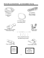
PUNCH 4-CHANNEL ACCESSORY PACK
12' (366cm)
Blue Remote
Turn-on Wire
17' (518cm)
Red Power
Wire
1.5' (46cm) Black
Grounding Wire
Power Ring
Terminals
Remote Turn-on Wire
Connector Plug
Allen Head Set Screws
and Mounting Screws
Fuse Holder 4080
Fuse Holder 4040
Punch
Owner's
Manual
Punch
Verification
Certificate
3
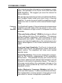
INTRODUCTION
This manual provides information on the features, installation, and operation of the Punch 4040 DSM and 4080
DSM Amplifiers. We suggest you save this manual for
future reference.
We strongly recommend you have your Authorized Rockford Fosgate Dealer install your new Punch 4-channel
amplifier. If you do choose to install the amplifier yourself,
please be sure to read the entire manual before beginning.
Features
and
Benefits
The Rockford Fosgate 4-Channel automotive stereo power
amplifiers provide state-of-the-art sound in cars, vans,
boats, or wherever a high current 12 volt power source is
available.
“Discrete Surface Mount” (DSM) technology is utilized
in the crafting of all of our Punch amplifiers. This process
provides greater ruggedness and consistency of both
components and layout. Already used heavily in aerospace and industrial applications, this technology is also
highly advantageous in the hostile automotive environment.
Low Level Input Senstivity. The Punch 4-channel adjustable input circuits are designed to match almost any
music source. The amplifiers will drive most normal
speaker types.
Punch Equalization. This circuit is designed to compensate for the acoustic inadequacies of the automotive
environment. This patented circuitry will correct for the
poor bass response and natural high frequency roll-off
inherent in the world of automotive stereo. The result is
full-range sound without the unpleasant changes in the
mid-range sound produced by most tone control and
equalizer circuits.
Active Electronic Crossover Modules built-into the
4040 and 4080 features 12 dB/octave Butterworth filters.
The independent crossover points in these plug-in modules allow for various configuration possibilities.
4
Real Time Power Protection (R.T.P.P.) allows for the
greatest power output under all load conditions. When
output reaches an unsafe level it will be reduced, unlike
current limiting which often causes premature protection
or failure to protect at all.
To get a better understanding of the Punch let’s take a
closer look.
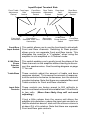
CONTROLS AND FEATURES
This section describes the various controls and features of
the Punch 4040 DSM and 4080 DSM amplifiers.
Top View of Amplifier and End Caps
Punch
4-Channel
Housing
The cast aluminum heatsink of the Punch 4-Channel is
designed for high performance cooling. The raised design
of the housing allows cables and wires to run underneath
the unit. This provides for greater wiring flexibility and
protects the cables from damage caused by excessive
heat and bending.
End Caps
Interchangeable end caps conceal the wiring and input
cables, giving the amplifier a clean, "stealth" look. Also
incorporated, is a holding dimple built into the end cap.
This small feature enables the cap to be held in place while
being mounted.
The end caps are secured to the housing with flush
mounting, captive screws.
5
Mounting
Screws
Four (4) custom, round, hex screws included in the accessory pack hold the unit in place. These screws are covered
when the end caps are installed.
Power/REM/LED Side
LED
Indicator
Rear Speaker
Output Terminals
REM
Connector
LED Power
Indicator
Front Speaker
Output Terminals
B+/GND
Power Connectors
REM
Connector
The Punch 4-Channel is turned on by connecting the blue
remote turn-on wire to the source unit’s “Accessory” or
“Auto Antenna” lead, either of which will go to +12 volts
when the source unit is turned on.
The LED illuminates when the unit is activated.
B+/GND
Power
Connector
These connectors are used to supply power and ground
to the amplifier and accept 12 gauge - 8 gauge wire.*
Speaker
Ouptut
Terminals
These gold-plated terminal blocks connect the Right/Left
Front and Right/Left Rear channel outputs to the speakers and accept wire sizes from 8 gauge through 18 gauge.
Gold-plated connectors are immune to corrosion that can
cause signal deterioration.
*Rockford Fosgate's Perfect Interface line of accessories includes high quality power and speaker wire, gold plated RCA
interconnecting cable and other products to complete your
installation. Ask your Authorized Rockford Fosgate Dealer about
Perfect Interface.
6
Input/Output Terminal Side
Front Treble Front Input
Adjustment
Gain
Control
Control
Front Input
Connectors
Front Bass
Adjustment
Control
Front+Rear
Summed Pass-Thru
Connectors
Rear Treble
Adjustment
Control
Rear Input
Connectors
Rear Input
Gain
Control
0/180° Rear
Phase Selector
Switch
Rear Bass
Adjustment
Control
Front/Rear
Input Switch
Front/Rear
Input Switch
This switch allows you to use the front input to drive both
Front and Rear channels. Switching to Rear position
allows you to run separate Front and Rear inputs. This
eliminates the need for a "Y-adapter" when using the
amplifier in a bi-amplified or 4-Channel mode.
0/180° Rear
Phase
Selector
Switch
This switch enables you to easily invert the phase of the
Rear channels on the amplifier without having to disconnect the speaker wires. See the wiring diagram on page
17 for use.
Treble/Bass
These controls adjust the amount of treble and bass
response desired. To increase the amount of response,
turn the controls clockwise; to decrease, turn the controls
counterclockwise. Note that there are separate Bass and
Treble controls for Front and Rear channels.
Input Gain
Controls
These controls are factory preset to 500 millivolts to
match most head units and are variable from 100 millivolts
to two volts. (More than likely they will not need
adjusting.)
If just a little volume from the source unit drives the
amplifier into distortion, reduce the input gain controls so
that the distortion doesn’t start until the source volume is
at about 3/4 of its rotation. Note that there are separate
Front and Rear gain controls.
7
Input
Connectors
The amplifier’s signal input, female, RCA jacks should be
connected to the source unit’s signal outputs with highquality RCA cables. The connectors have been plated in
gold to eliminate the possibility of corrosion that can cause
signal deterioration.
Front & Rear
Summed
Pass-Thru
Connectors
These pass-thru connectors allow you to daisy-chain an
additional Punch amplifier without running an additional
set of RCA cables from the front of the vehicle to the rear
amplifier location. The crossover module in the Pass-Thru
RCA circuit allows the daisy-chained amplifier to be configured independently of the Front and Rear channels for
low pass, high pass or full range operation.
The Pass-Thru signal is derived by summing the Front Left
and Rear Left inputs to create the Left output, and summing the Front Right and Rear Right input to create the
Right output. This provides constant output regardless of
the source unit fade position.
INSTALLATION CONSIDERATIONS
This section focuses on some of the vehicle considerations for installing your new Punch 4-Channel amplifier.
Checking your battery and current sound system, as well
as pre-planning your system layout and best wiring routes
will save installation time. When deciding how to lay out
your new system, be sure that each component will be
easily accessible for making adjustments.
Before beginning any installation, be sure to follow these
simple rules:
1. Carefully read and understand the instructions before
attempting to install the amplifier.
2. For easier assembly, we suggest you run all wires
prior to mounting your amplifier in place.
3. Use only quality connectors for making connections.
See your Authorized Rockford Fosgate Dealer for
Perfect Interface wire enhancements.
8
4. Think before you drill! Be careful not to cut or drill
into gas tanks, fuel lines, brake or hydraulic lines,
vacuum lines or electrical wiring when working on
any vehicle.
5. For safety, disconnect the battery ground cable prior
to beginning the installation process.
6. Never run wires underneath the vehicle. The cleanest,
safest wiring connections are made by running the
wire under the carpet or behind the side panels.
Never leave wires exposed.
7. Avoid running wires over or through sharp edges.
Use grommets to protect wires routed through holes
in metal.
8. ALWAYS protect the battery and electrical system
from shorts with proper fusing. A fuse holder and fuse
must be installed within 18” (46cm) of the battery
terminal to safeguard from possible damage or injury.
9. Grounding connections should be as short as possible and always be connected to metal that is
welded to the main body, or chassis, of the vehicle.
Tools
Needed
The following is a list of tools you will need for installing
the Punch amplifier:
7/64" & 3/32" Allen Wrenches (included)
Wire Strippers
Wire Cutters
Battery Post Wrench
Voltmeter
Electric Hand Drill with assorted bits Wire Crimpers
BATTERY AND CHARGING
Punch amplifiers will naturally put an extra load on your
battery and charging system. We recommend you check
your alternator capacity to ensure ample charging capability to handle the additional load of your new Punch
equipment. Stock electrical systems in good condition
should typically handle the extra load of any individual
Punch unit without problems. If problems arise, we suggest you first check the charging system, then use a heavy
duty battery and/or a high output alternator as needed.
9
MOUNTING AND LOCATION
The mounting location and position of the Punch 4Channel will have a great effect on its ability to dissipate
the heat generated in normal operation. The Punch 4Channel has a heatsink designed for heat dissipation
and internal shutoff circuitry to avoid overheating. It is
reasonably tolerant of mounting variations. However,
care should be taken to ensure adequate ventilation.
Trunk
Mounting
The temperature inside a trunk can reach as high as 175°
F (80° C) during the summer months. Since the thermal
shutoff point for the Punch 4-Channel is 195° F (90° C),
it is easy to see that the amp must be mounted for
maximum cooling capability. Mounting the amplifier on
the floor or under the rear parcel tray prevents sufficient
convectional air flow cooling. Mounting the unit vertically
on a surface with the fin grooves running up and down
usually results in the best cooling.
Passenger
Compartment
Mounting
Under the seat or floor mounting will work as long as there
is a minimum of 1” (2.5cm) of air gap above the amplifer's
heatsink.
Vertical mounting of the amplifier is still the best.
WIRING THE PUNCH
Caution! Be sure to avoid running the power wires
near the low level input cables, antenna, power leads,
sensitive equipment or harnesses. The power wires
carry substantial currents and could induce noise.
Preparing
Wires and
Fuses
The following instructions explain how to prepare the
wires, connectors and fusing. We suggest you perform
these procedures prior to wiring and mounting your new
Punch 4-Channel amplifier.
Wiring the
Fuse Holder
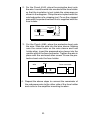
1. Use approximately 18" (46cm) of the red power wire.
Strip one end of the wire back 1/2” (1.3cm) as shown
in the following diagram:
1/2" >
>
(1.3cm)
(1.27cm)
10
2. For the Punch 4040, place the protective boot onto
the wire. Insert the wire into one end of the fuse holder
so that the insulation is just inside the crimp area as
shown in the diagram. Crimp the wire in place with the
notched portion of a crimping tool. Cover the crimped
area with the protective boot that is supplied with the
fuse holder.
{
Crimp Here
Fuse Holder
Protective Boot
3. For the Punch 4080, place the protective boot onto
the wire. Slide the wire into the wire sleeve. Making
sure the screw holes on the wire sleeve and fuse
holder align, insert the prepared wire sleeve into the
smaller end of the fuse connector. Tighten the wire in
place with the enclosed allen screw. Screw the protective boot onto the fuse holder.
wire
wire
fuse connector
wire sleeve
4. Repeat the above steps to connect the remainder of
the red power wire to the other side of the fuse holder
and route to the amplifier mounting location.
11
Wiring the
Ring and
Spade
Connectors
1. Strip back approximately 3/8" (1cm) of insulation.
3/8"
(1cm)
2. Insert the bare wire into the connector and crimp in
place as shown in the following diagram:
This connector is used for
the Red Power wire and
Black Ground wire.
Crimp Here
{
Connectors
{
Wire w/insulation
This connector is for the
Blue Remote Turn-On wire.
Crimp Here
Power
Bare
Wire
The gold B+ terminal on the amplifier must be connected
directly to the positive (+) terminal of the battery with an
appropriate size fuse. (See the Specifications Table for
more information.) This provides a power source with a
low voltage drop and low noise. Be sure to use the
supplied fuse and fuse holder within 18" (46cm) of
the battery’s positive terminal. Failure to do so may
cause damage to the vehicle and the amplifier.
If the power wire must be extended beyond 17' (518cm),
we recommend you use 8 gauge, or heavier, stranded
wire.
Using Larger
Gauge Wire
If using a larger gauge wire than that supplied with your
new Punch 4-Channel, cut the wire casing on the diagonal as shown in the following diagram. Insert the wire into
the connector. Twist the wire around so that the long end
of the insulation faces up. Bend the wire prior to tightening
in place. This will make it easier for attaching the end cap
to the amplifier.
Note: For easier assembly, only 5/8" (1.6cm) of wire
should be bare.
12
INSULATION
STRIP WIRE
>
<
5/8"
>
>
AMP
>
Ground
The GND terminal grounds the amplifier and is connected to the chassis of the vehicle with 12 gauge, or
heavier, stranded wire. When grounding, scrape paint off
metal to ensure a good, clean ground connection. To
prevent ground loops, we recommend you refrain from
extending the ground wire beyond 18" (46cm) in any
installation.
Remote
Turn-on
The Punch 4-Channel amplifiers are turned on by supplying positive (+) 12 volts to the REM terminal. Usually the
terminal is connected to the source unit’s “Accessory” or
“Auto Antenna” lead, either of which will go to +12 Volts
when the source unit is turned on.
Although the majority of high-quality automotive source
units have an Accessory or Antenna output, there are
many which require different turn-on methods. If the
source unit has no Auto Antenna lead (or if the Auto
Antenna goes down during tape operation), we recommend a switch in the car with one terminal connected to
+12 volts and the other to the Punch 4-Channel REM
lead. This will allow you to engage the amplifier manually.
Input
The amplifier’s signal input RCA jacks should be connected to the source unit’s signal outputs with highquality braided or double-shielded interconnecting RCA
cables.
Note: Be sure to route the Punch 4-Channel signal
input cable away from the main power wire and the
car’s wiring harnesses to avoid noise coupling.
13
Speakers
Punch 4-Channel amplifiers are rated for safe operation
into loads of 2Ω, or greater in stereo mode or 4Ω in
bridged/mono configurations. The primary loads on any
amplifier come from directly connected speakers without
using capacitors. The measured resistance for each side
should not be less than 2Ω stereo or 4Ω bridged/mono.
Bridged/Mono
Configuration
The Punch 4-Channel amplifiers are capable of bridged/
mono configurations.
This configuration enables you to:
• Run amplifier as a separate 2 channel subwoofer or
satellite amplifier.
• Create a high power stereo system
• Run 2 channels with a bridged mono woofer and the
other 2 as a high-frequency stereo amp, etc.
Note: Both Punch 4-Channel amplifiers allow the
above 3 configurations all in one.
For more information refer to the wiring diagrams beginning on page 18.
Note: To bridge the amplifier use the L+ and R–
speaker connectors.
Caution! Punch 4-Channel amplifiers are not recommended for impedance loads below 2Ω stereo or 4Ω
bridged/mono.
Be sure to observe proper speaker terminal polarity
throughout the system. It is critical for the Punch 4Channel to use the correct negative terminals for
right and left channels, since the RIGHT NEGATIVE
(–) terminal is the “hot” terminal for the right speaker.
DO NOT chassis ground any of the speaker leads as
unstable operation may result.
Passive
Crossover
Impedance
A passive crossover is a circuit that employs capacitors
and/or coils and is placed on speaker leads between the
amplifier and speaker to delegate frequencies in the
speaker’s optimum performance range.
14
The most commonly used filter networks are 6 dB per
octave systems. These are easy to construct and require
a minimum number of parts. A filter network can perform
one of three functions. These are highpass (capacitors),
lowpass (inductors, chokes or coils) and bandpass (combination of a capacitor and a coil).
The result, limiting the types of frequency to the speaker,
is directly dependent upon the speaker’s impedance and
component values.
The most common filters used in speaker crossovers, as
stated above, are 6 dB per octave which use one component per filter. Placing this filter in series with the circuit will
reduce power to the speaker by 6 dB per octave above or
below the crossover point depending on whether it is a
High Pass or Low Pass filter. When passive crossover
components are used in multiple speaker systems, the
crossover system's effect on the overall impedance should
be taken into consideration along with the speaker's
impedance when determining amplifier loads.
More complex systems such as 12 dB or 18 dB per octave
can cause impedance problems if not professionally designed. If such a system is required, we recommend
consulting an Authorized Rockford Fosgate Dealer.
15
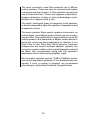
Table of Component Values
C
L
6 dB/Octave Low Pass
Freq.
Hertz
6 dB/Octave High Pass
Speaker Impedance
2 OHMS
8 OHMS
4 OHMS
L
C
L
80
100
130
4.1mH
3.1mH
2.4mH
1000µF
800µF
600µF
8.2mH
6.2mH
4.7mH
200
260
400
1.6mH
1.2mH
.8mH
400µF
300µF
200µF
600
800
1000
.5mH
.41mH
.31mH
1200
1800
4000
6000
9000
12000
C
L
C
500µF
400µF
300µF
16mH
12mH
10mH
250µF
200µF
150µF
3.3mH
2.4mH
1.6mH
200µF
150µF
100µF
6.8mH
4.7mH
3.3mH
100µF
75µF
50µF
136µF
100µF
78µF
1.0mH
.82mH
.62mH
68µF
50µF
39µF
2.0mH
1.6mH
1.2mH
33µF
26µF
20µF
.25mH
.16mH
.08mH
66µF
44µF
20µF
.51mH
.33mH
.16mH
33µF
22µF
10µF
1.0mH
.68mH
.33mH
16µF
10µF
5µF
51µH
34µH
25µH
14µF
9.5µF
6.6µF
.10mH
68µH
51µH
6.8µF
4.7µF
3.3µF
.20mH
.15mH
100µH
3.3µF
2.2µF
1.6µF
6 dB/Octave High and Low Pass Filters
L = Low Pass (Inductor)
C = High Pass (Capacitor)
For more information, see your Authorized Rockford Fosgate Dealer.
16
The Punch 4-Channel amplifiers feature selectable electronic crossovers. Selection is made by positioning of a
removable module card. These modules control the
output channels and can be configured in a High Pass,
Low Pass or Full Range (factory default) position. The 4Channel amplifiers are shipped with 100Hz 12dB per
octave Butterworth aligned crossover modules. Additional crossover frequency modules are available from
your Authorized Rockford Fosgate Dealer.
LP
➞
➞
HP
Note:
To change the crossover mode, remove the crossover
module from the housing. Rotate the module to the
desired setting and gently push the module back into the
amplifier housing as shown on the diagram on the back
of the amplifier.
NOTE:
REAR
SPEAKERS
All of the crossover cards in this amplifier have been
factory installed in the FULL RANGE configuration.
They can be reconfigured to produce a 100Hz LOW
PASS or HIGH PASS according to the following
instructions.
CROSSOVER CARD INSTALLATION:
Use a small screwdriver to pry out the plastic hole
covers. Orient the card in the FULL RANGE, LOW
PASS, or HIGH PASS configuration as shown below,
then insert the card fully into the connector.
LOW PASS
➝
LP
HIGH PASS
➝
➝
➝
➝
FULL
➝
FULL RANGE
HP
Crossover
Frequency
Settings
The factory default is Full Range.
LP
Active
Crossover
Mode
Selection
HP
FRONT
SPEAKERS
FRONT+REAR SUM OUTPUT:
FRONT+REAR
SUM OUTPUT
The center pair of RCA jacks provide a
FRONT+REAR summed output signal, with a
crossover that operates independently of the FRONT
SPEAKER and REAR SPEAKER crossovers.
Example: The 4040 DSM is shipped with three 100 Hz
modules. With the modules in the Full Range setting, the
amplifier will pass through all 20Hz -20kHz frequencies.
In the Low Pass setting, only those frequencies below
100 Hz will pass through the amplifier.
In the High Pass setting, only those above 100 Hz will
pass through the amplifier.
17
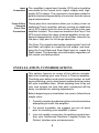
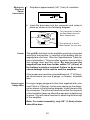
SAMPLE WIRING DIAGRAMS
SOURCE UNIT
IN
OUT
IN
R
R
L
L
0
TREBLE GAIN
BASS
TREBLE GAIN
FRONT
FRONT
FRNT+REAR
BASS
180 R
F
PHASE
INPUT
REAR
REAR
Input switch set to F
Front crossover set to 100 Hz High Pass
Rear crossover set to 100 Hz Low Pass
Front+Rear summed output not used
Phase switch set to 0°
*
REM
REAR
(bridge)
+ LEFT–
B+
GND
FRONT
(bridge)
+RIGHT–
+
+ LEFT–
+RIGHT–
–
4Ω Woofer
–
+
–
+
4 Ohm (2Ω min.) 4 Ohm (2Ω min.)
Mid Range/
Mid Range/
Tweeter
Tweeter
BRIDGED MONO/BI-AMPLIFIED
* Always start with the phase switch on 0°, then switch to 180° and listen.
Select the position that provides the best frequency response.
18
SOURCE UNIT
Left
Right
IN
OUT
IN
R
R
L
L
0
TREBLE GAIN
BASS
TREBLE GAIN
FRONT
FRONT
FRNT+REAR
BASS
180 R
F
PHASE
INPUT
REAR
REAR
Input switch set to R
Set Front & Rear crossover to the same point
Front+Rear summed output not used
Phase switch set to 0°
*
REM
REAR
(bridge)
+ LEFT–
+RIGHT–
+
–
4Ω
Right
B+
GND
FRONT
(bridge)
+ LEFT–
+RIGHT–
+
–
4Ω
Left
2-CHANNEL BRIDGED STEREO
* In this mode the phase switch should always be at 0°. Switching to the 180°
position will result in an "out of phase" condition and a loss of output.
(Alternate Version: 100Hz High Pass Front & Rear -4Ω Full Range)
19
SOURCE UNIT
IN
OUT
R
IN
R
0
TREBLE GAIN
BASS
TREBLE GAIN
FRONT
L
FRONT
L
FRNT+REAR
BASS
180 R
F
PHASE
INPUT
REAR
REAR
Input switch set to F
Set Front & Rear crossover to the same point
Front+Rear summed output not used
Phase switch set to 180°
*
REM
REAR
(bridge)
+ LEFT–
B+
GND
FRONT
(bridge)
+RIGHT–
+ LEFT–
Left
–
Right
+
4Ω
Subwoofer
+RIGHT–
+
–
4Ω
Subwoofer
2-CHANNEL BRIDGED STEREO
* In this mode the phase switch should always be at 180°. Switching to the 0°
position will result in an "out of phase" condition and a loss of output.
(Alternate Version: 100Hz High Pass Front & Rear -4Ω Full Range)
20
SOURCE UNIT
IN
OUT
IN
R
R
L
L
0
TREBLE GAIN
BASS
TREBLE GAIN
FRONT
FRONT
FRNT+REAR
BASS
180 R
F
PHASE
INPUT
REAR
REAR
Input switch set to F
Front crossover set to 100 Hz High Pass
Rear crossover set to 100 Hz Low Pass
Front+Rear summed output not used
Phase switch set to 0°
*
REM
+ LEFT–
–
+RIGHT–
GND
+RIGHT–
+
+ LEFT–
B+
FRONT
(bridge)
–
REAR
(bridge)
+
4 Ohm (2Ω min.) 4 Ohm (2Ω min.)
Mid Range/
Mid Range/
Tweeter
Tweeter
+
–
Subwoofer
+
–
Subwoofer
BI-AMPLIFIED STEREO
* Always start with the phase switch on 0°, then switch to 180° and listen.
Select the position that provides the best frequency response.
21
SOURCE UNIT
IN
OUT
R
IN
R
0
TREBLE GAIN
BASS
TREBLE GAIN
FRONT
L
FRONT
L
FRNT+REAR
BASS
180 R
F
PHASE
INPUT
REAR
REAR
Input switch set to Rear
Front crossover set to Full Range
Rear crossover set to Full Range
Front+Rear summed output not used
Phase switch set to 0°
REM
+ LEFT–
GND
+RIGHT–
–
+
Full Range
–
+
–
+
Full Range
+RIGHT–
+
+ LEFT–
B+
FRONT
(bridge)
4Ω (2Ω min.)
Mid Range/
Tweeter
4Ω (2Ω min.)
Mid Range/
Tweeter
+
–
REAR
(bridge)
–
4Ω
Subwoofer
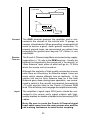
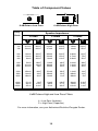
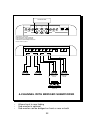
4-CHANNEL WITH BRIDGED SUBWOOFER
•
•
•
Allows front to rear fading
Sub-woofer is optional
Sub-woofer can be bridged on front or rear or both
22
SOURCE UNIT
IN
OUT
R
IN
R
0
TREBLE GAIN
BASS
TREBLE GAIN
FRONT
L
FRONT
L
FRNT+REAR
BASS
180 R
F
PHASE
INPUT
REAR
REAR
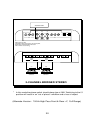
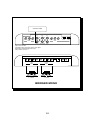
Input switch set to Rear
Front crossover set to Full Range
Rear crossover set to Full Range
Front+Rear crossover set to 100Hz Low Pass
Phase switch set to 0°
REM
+ LEFT–
GND
+RIGHT–
–
+
–
+
–
Full Range
+
Full Range
Full Range
Full Range
LR
+RIGHT–
+
+ LEFT–
B+
FRONT
(bridge)
–
REAR
(bridge)
RL
L
+
BIAMPLIFIED
4-CHANNEL
with SUBWOOFER AMP
R
–
Subwoofer
4-CHANNEL WITH SUBWOOFER AMP
23
SOURCE UNIT
IN
OUT
IN
R
R
L
L
0
TREBLE GAIN
BASS
TREBLE GAIN
FRONT
FRONT
FRNT+REAR
BASS
180 R
F
PHASE
INPUT
REAR
REAR
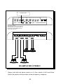
Input switch set to F
Set Front & Rear crossovers to the same point
Front+Rear summed output not used
Phase switch set to 0° *
REM
REAR
(bridge)
+ LEFT–
FRONT
(bridge)
+RIGHT–
+
–
4Ω Woofer
+ LEFT–
+RIGHT–
+
–
4Ω Woofer
BRIDGED MONO
24
B+
GND
TROUBLESHOOTING
Problem
Amplifier will not play – Remote turn-on light is off.
Solution
1. Check the DC voltage at the amplifier's B+ terminal
with a voltmeter. The voltage should measure between 11.5V - 15.5V.
If voltage is not found, check the battery, fuse, fuse
housing and wire connections. Fix, repair, or replace
accordingly.
2. If the amplifier still does not play, check the voltage at
the amplifier's remote turn-on lead. The voltage should
measure between 11V - 15V.
a. If voltage is above or below the prescribed measurements, have the head unit checked by an
Authorized Dealer or Service Center.
b. If the remote turn-on current draw from the head
unit is connected to multiple amps and/or electronics, the current draw may be too great. Check for
proper connections. (Use a relay to suppress the
excessive current draw.)
If you are still having problems, have the amplifier checked
by an Authorized Rockford Fosgate Dealer.
Problem
Amplifier will not play – Remote turn-on light is on:
Solution
1. Unplug the head unit and test the amplifier with another working source unit (i.e., bench-test radio,
walkman, etc.) If the amplifier plays, check the in-dash
leads for cuts, breaks and/or shorts.
2. If the amplifier still does not play, disconnect the
existing speakers and connect a set of test speakers
to the output of the amplifier (any type of speaker will
do - i.e., simple home box type, bookshelf, raw speaker,
etc.). If the amp plays, check for shorts or blown voice
coils in the vehicle's speaker system.
If you are still having problems, have the amplifier checked
out by an Authorized Rockford Fosgate Dealer.
25
Problem
Amplifier gets too hot.
Solution
1. Be sure the amplifier is properly mounted. You should
be able to place your hand a few inches above the
amplifier housing and feel the heat rising when the unit
is on.
Hot air rises, consequently, mount the amplifier with
the heatsink fins aligned vertically. This allows the air
to flow freely, carrying away the heat. Check to see
that the heatsink fins are free of any obstruction (i.e.,
carpet, seats, etc.).
2. If #1 does not solve the problem, check to see that the
impedance of the overall system is not less than 2Ω as
described on page 14. Using an AC impedance meter
(Perfect Interface IM-1), sweep from 20 Hz - 20 kHz,
and look for dips below the 2Ω rating.
Be sure to test the bass region (20 Hz - 150 Hz) of your
system. If the amplifier is bridged to those speakers,
the load the amp sees is one-half (1/2) of the reading
on the AC impedance meter.
If the impedance level is below 2Ω, check for bad
speakers and/or crossovers, proper use of passive
crossovers, or try rewiring the entire system.
Problem
Amplifier Noise (Turn-On Pop)
Solution
1. Disconnect the RCA plugs from the amplifier and
recheck the amp by turning the unit on and off. If turnon pop goes away, connect a delay turn-on module
(Perfect Interface DT-1) to the amplifier. (See your
Authorized Rockford Fosgate Dealer for more information.)
2. If the noise persists, disconnect the turn-on wire from
the head unit and use a different +12 volt power source
to turn on the amplifier (i.e., battery direct). If the noise
is gone, use a relay to switch +12 volts auto power
from the clean power source.
26
Problem
Engine Noise (Whine)
Solution
1. Disconnect the speakers from the amplifier. Connect
a test speaker to the amplifier output terminals. If the
noise goes away, check your speaker leads, speakers
and crossovers.
2. If the noise persists, use a "shorting plug" to mute the
input signal at the amplifier. If the noise goes away:
a. Bypass all of the other equipment (i.e., crossovers
and equalizers) and connect the head unit directly
to the amp. If the noise disappears, reconnect the
equipment, being sure to test for noise after each
install. Logic indicates that the last unit installed is
the culprit. Refer to the unit's owner's manual for
more information.
b. If the noise persists, connect a new RCA line from
the head unit to the amplifier. If there is no noise,
replace the RCA cable.
c. If the noise is still present after replacing the RCA
cable, run the RCA cable on a different route.
d. Isolate the grounds in your head unit so there is
only one grounding point. If the noise disappears,
install the radio, using only one (1) grounding point.
Isolate the radio chassis from the grounding on the
dash, and use an antenna grounding loop isolator
on the antenna.
If noise still persists, see your Authorized Rockford
Fosgate Dealer.
27
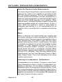
DYNAMIC POWER MEASUREMENTS
About the Dynamic Power Measurements
The Audio Graph PowerCube is a test instrument used to
measure the output of an amplifier in accordance with
IHF-202 industry standards. The IHF-202 standard is a
Dynamic power measurement and was developed as a
means of measuring power in a manner that best represents the Real World operation of an amplifier. Many
manufacturers, including Rockford Fosgate, at times will
measure amplifier power into a fixed resistor (4 ohm, 2
ohm). While this method is useful in some types of
evaluation and testing, it is not representative of an
amplifier that is connected up to a speaker and playing
music.
Music
Music is dynamic; the sound waves are complex and
constantly changing. In order to simulate this, the IHF-202
standard calls for the input signal to the amplifier to be a
1kHz bursted tone. This signal is input (on) for a short
period of time and then off for a “rested” period. The signal
is gradually increased in level until the amplifier's output
exceeds 1% Total Harmonic Distortion (THD). At 1%
distortion becomes audible, therefore, any power produced above that level is considered unusable. Many
manufacturers represent their amplifiers' output power in
excess of 10% distortion. They use many names for this
measurement, such as Total Maximum Power or Maximum Output Power. This is not indicative of the actual
usable output power.
Listening to Loudspeakers - Not Resistors
A loudspeaker is not a resistor. A resistor's value (resistance measured in ohms) is fixed. A loudspeaker's impedance is dynamic. It is constantly changing in value,
dependent upon the frequency of the input signal. Therefore, measuring power with the amplifier loaded into a 4
ohm resistor is not the same as measuring power with the
amplifier connected to a 4 ohm speaker. Most people do
not listen to music through a resistor.
Appendix A
28
A 4 ohm speaker may experience a drop in impedance 46 times lower than its nominal (printed) impedance. A
speaker will also create phase shifts in the signal that is
passed through it. These phase shifts happen because
a speaker is an inductor (voice coil) and a capacitor
(compliance of the surround/spider), as well as a resistor
(voice coil wire).
To simulate a speaker the Audio Graph PowerCube
measures output power into 20 different loads. It tests at
8 ohms, 4 ohms, 2 ohms and 1 ohm. Each of these
impedances is also tested at –60°, –30°, 0°, +30° and
+60° phase angles. These different impedances and
phase angles represent the shifts in impedance and
phase that can occur in a typical loudspeaker.
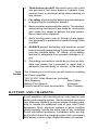
Information Cubed
The data acquired in the testing procedure is then graphed
in the form of a 3-dimensional cube, hence the name
PowerCube.
The Phase Angle is expressed on the horizontal axis, the
Output Voltage is presented on the vertical axis and the
Impedance is displayed on the Z axis. Output Power, in
watts, is listed on the left hand side for each impedance
at each phase angle.
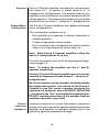
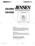
Audio Graph – The PowerCube
MODEL BEING
TESTED
x4 = STEREO
MONO = BRIDGED MONO*
VOLTAGE FROM
BATTERY
I M P E D A N C E
Amplifier: PUNCH 4040 14.4V x 4
Serial No: B1AB13A000016
Owner : ROCKFORD CORPORATION
{
Rated Power : 20W at 4 Ohms
OUTPUT VOLTAGE
AT THE RAILS
(MOSFETS)
POWER
IN
WATTS
100V
60V
20V
8Ω
4Ω
2Ω
–60° (Cap)
0°
1Ω
(Ind) +60°
PHASE ANGLES
"MOTION OF
SPEAKER"
*If a Bridged/Mono, test amplifier sees 1/2 impedance (2Ω test amp sees 1Ω)
29
{
{
8Ω*–60° 20 W
–30° 20 W
0° 19 W
30° 20 W
60° 20 W
4Ω*–60° 38 W
–30° 35 W
0° 35 W
30° 36 W
60° 38 W
2Ω*–60° 66 W
–30° 60 W
0° 58 W
30° 60 W
60° 64 W
1Ω*–60° 100 W
–30° 87 W
0° 84 W
30° 87 W
60° 100 W
MANUFACTURERS
RATED OUTPUT
e
danc
Impe
What is an Amplifier?
An amplifier by definition is a voltage generating device,
recreating the signal which is input to in an identical but
amplified form. It will be connected to a reactive load (the
speaker). The impedance of this load and phase of the
signal passing through the load will vary, dependent upon
the frequency and amplitude of the input signal (music).
Therefore, a perfect amplifier will be able to maintain the
same output voltage regardless of load characteristics
and will not alter the signal it is reproducing. A perfect
amplifier when measured by the AudioGraph PowerCube
would present data that forms a perfect cube. Unfortunately, amplifiers are not perfect. The laws of physics
generally prevent it. A great amplifier is about the best
one can hope for.
As you can see by the PowerCube and as you will
experience by listening, your Punch amplifier is a GREAT
AMPLIFIER!
30
WARRANTY INFORMATION
Rockford Fosgate warrants all electronics to the original consumer/purchaser to be
free from defects in materials or workmanship for a period of three (3) years. We will
cover parts and labor provided the product was purchased from an Authorized
Rockford Fosgate Dealer. This warranty does not apply to any product on which the
seals and/or serial number have been broken, removed, tampered with, defaced or
altered in any manner. This warranty applies only to the original consumer/
purchaser and is not transferable.
Electronics found to be defective during the warranty period will be repaired or
replaced at Rockford Fosgate’s discretion. Repaired or replaced electronics will be
covered by the balance of the original warranty period only. Rockford Fosgate shall
not be responsible for any incidental or consequential damages resulting from a
defect in electronics. Some states do not allow the exclusion or limitation of
incidental or consequential damages, so the previous limitation may not be applicable.
The warranty does not cover any appearance item, any cost or expense related to
the removal or reinstallation of the product, any accessory used in conjunction with
the product, damage to the product resulting from alteration, accident, misuse or
abuse, or improper installation. This warranty does not apply if the parts or labor,
which would otherwise be provided without charge under this warranty, are obtained
from any source other than Rockford Fosgate or an Authorized Rockford Fosgate
Service Center.
This warranty is the only express warranty and does not create any implied
warranties. Rockford Fosgate limits its obligations under any implied warranties
under state laws to a period not to exceed the written warranty period. Some states
do not allow limitation on how long an implied warranty lasts, so the above limitation
may not apply. This warranty applies only to products sold in the United States of
America or its possessions. For warranty outside the U.S.A., please contact the
nearest Authorized Rockford Fosgate Dealer. This warranty gives the consumer
specific legal rights, and the consumer may have other rights which vary from state
to state.
A defective product must be shipped prepaid to the Authorized Rockford Fosgate
Dealer from which the consumer purchased the product or to the Rockford Fosgate
factory in Tempe, Arizona in the original factory carton or equivalent. Any shipping
loss or damage will be borne by the consumer or the consumer’s shipper. A
consumer returning a product to the factory should call (800) 669-9899 for a Return
Authorization Number. All shipments shall be clearly marked with the Return
Authorization Number on the outside of the shipping carton.
Rockford will provide free shipping for electronics under warranty to Authorized
Rockford Fosgate dealers. Prepaid, pre-addressed Federal Express airbills are
available by calling Rockford Customer Service at 1-800-669-9899.
Ship to:
Rockford Corporation
Warranty Repair Department
2055 E. 5th Street
Tempe, AZ 85281 U.S.A.
Return Authorization Number:_________________
Rockford Fosgate
A Division of Rockford Corporation
546 South Rockford Drive
Tempe, Arizona 85281 U.S.A.
In U.S.A., (602) 967-3565
In Canada, call Korbon (416) 567-1929
In Europe, Fax (49) 4207-801250
REV. B 4/93
MAN-0288