1
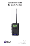
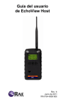
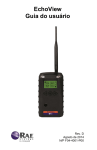
EchoView Host Mini-Controller for Closed-Loop Portable Wireless Solutions User’s Guide Rev. B November 2012 P/N F04-4006-000 © Copyright 2012 RAE Systems, Inc. EchoView Host User’s Guide Contents 1 2 3 4 5 6 7 8 Standard Kit ............................................................................. 6 General Information ................................................................. 6 Physical Description .............................................................. 10 3.1 LCD Display (Monitoring) ...................................... 11 3.2 LCD Display (In Alarm) .......................................... 11 Specifications ......................................................................... 12 Operation................................................................................ 13 5.1 Turning The EchoView Host On ............................. 13 5.2 Turning The EchoView Host Off ............................ 15 5.3 Battery Indicator ...................................................... 15 5.4 Buzzer (Audible Alarm) Off Indicator .................... 16 5.5 Wireless Communication Indicator ......................... 16 Deploying The EchoView Host ............................................. 17 Programming The EchoView Host ........................................ 17 7.1 Settings ..................................................................... 19 7.1.1 Buzzer On/Off ................................................... 20 7.1.2 LCD Contrast .................................................... 20 7.1.3 Serial Number ................................................... 21 7.1.4 Firmware Version ............................................. 22 7.1.5 Factory Reset .................................................... 22 7.1.6 Edit Password.................................................... 23 7.1.7 Page Disable...................................................... 25 7.1.8 Exit .................................................................... 25 7.2 Wireless.................................................................... 26 7.2.1 Ping Net ............................................................ 27 7.2.2 PAN ID Setup ................................................... 28 7.2.3 Form Net ........................................................... 29 7.2.4 Channel Setup ................................................... 30 7.2.5 Exit .................................................................... 31 Viewing Data From Connected Monitors .............................. 32 8.1 One Monitor In Alarm ............................................. 33 8.2 Multiple Monitors In Alarm..................................... 33 8.2.1 Alarm Abbreviations ......................................... 35 8.2.2 Alarm Signal Summary..................................... 36 8.3 Offline Monitor(s) .................................................... 36 3 EchoView Host User’s Guide 8.4 Backlight .................................................................. 36 9 Internal Battery Replacement ................................................ 37 9.1 Proper Battery Disposal ........................................... 38 10 Troubleshooting .............................................................. 39 11 Year Of Manufacture ...................................................... 40 4 EchoView Host User’s Guide WARNINGS Read Before Operating This manual must be carefully read by all individuals who have or will have the responsibility of using, maintaining, or servicing this product. The product will perform as designed only if it is used, maintained, and serviced in accordance with the manufacturer’s instructions. Warning: Use only the Lithium battery or external rechargeable battery provided by RAE Systems. This instrument has not been tested in an explosive gas/air atmosphere having an oxygen concentration greater than 21%. Substitution of components may impair suitability for intrinsic safety. Replace batteries only in non-hazardous locations. STATIC HAZARD: Clean only with a damp cloth. For safety reasons this equipment must be operated and serviced by qualified personnel only. Read and understand instruction manual completely before operating or servicing. Any rapid up-scale reading followed by a declining or erratic reading may indicate a gas concentration beyond upper scale limit, which may be hazardous. Intrinsically Safe Marking Cl. I, Div. 1, Gr A, B, C, D T4 -40° C < Tamb < 50° C IECEx TSA 10.0016X Ex ia I/IIC T4 0575 IM1/II 1G Ex ia I/IIC T4 DNV 10 ATEX 83388X Ui = 3.6V, Ci=78µF, Li/Ri=3.5µH/ohm Warning Substitution of components may impair suitability for intrinsic safety. Replace batteries only in non-hazardous locations. Warning To prevent ignition of flammable or combustible atmospheres, disconnect power before servicing. 5 EchoView Host User’s Guide 1 Standard Kit EchoView Host Mini Controller Antenna Swivel Belt Clip Maintenance/battery replacement tool User’s Guide 2 General Information The EchoView Host Mini-Controller is the cornerstone of RAE Systems’ Closed-Loop Wireless Solutions for portable gas monitors. This rugged handheld device can establish a self-sufficient network with up to eight supported RAE Systems portable wireless monitors and display their readings and alarm status in real time on an easy-to-read screen, supplemented by audible and visible alerts. One EchoView Host and up to eight ToxiRAE Pro and/or MultiRAE monitors. The EchoView collects data from all eight monitors and displays it. 6 EchoView Host User’s Guide Extending the range between monitors and an EchoView Host. If a long distance is between the portable monitors and the EchoView Host, Mesh Routers can be employed to extend the range. Up to three Mesh Routers can be used in this configuration, and each can extend the range by up to 300 meters, typical. 7 EchoView Host User’s Guide 8 EchoView Host User’s Guide 1.1. Key Features • Remote wireless access to real-time readings and alarm status of portable gas monitors for faster incident response • Establishes a closed-loop wireless network with and displays real-time readings and alarm status of up to eight portable gas monitors at the same time • Communication range extendable to 1 km / 0.6 mi with Mesh Routers • Field-replaceable battery with a 10-day runtime • Bright-red high-visibility alarm lights • Loud audio alarm, 90dB at 30cm • Highly-resistant to electromagnetic and radio interference • IP-65 water and dust ingress protection rating • Intrinsically safe for Class I, Division 1 ATEX/IECEx hazardous locations 9 EchoView Host User’s Guide 3 Physical Description 6 1 2 5 3 4 1 2 3 4 5 6 LED alarm LCD (with backlighting) Buzzer alarm Battery cover (on bottom) Y/+, MODE, and N/- keys Antenna 10 EchoView Host User’s Guide 3.1 LCD Display (Monitoring) 4 1 2 5 3 6 1 2 3 4 5 6 Selected monitor (solid circle or star)* Unselected monitor (open circle or star) Offline monitor (open circle with “X”) Radio transmission indicator (“H” for “Host”) Audible alarm on/off indicator (“on” shown) Battery indicator Note: The Unit ID can be a device ID as well as a radio ID, depending on the portable monitor’s setting. 3.2 LCD Display (In Alarm) 1 4 2 5 6 3 1 2 3 4 5 6 Monitor in alarm and selected (solid star) Unselected monitor in alarm (open star) Unselected monitor not in alarm (open circle) Radio transmission indicator (“H” for “Host”) Audible alarm on/off indicator (“on” shown) Battery indicator 11 EchoView Host User’s Guide 4 Specifications RF Certifications Display Audible alarm Visual alarm Calibration EM Immunity Operating Range User Interface Power Supply Operation Time Operating Temperature Humidity Dimensions Weight IP Rating Mounting FCC Part15 CE EN 300328 Graphical LCD (1 x 1.5″) with backlight 90dB @ 30cm 2 super-bright red LEDs None necessary No effect when exposed to 0.43mW/cm2 RF interference (5-watt transmitter at 12") Up to 300 meters/990 feet to Mesh Router, or up to 100 meters/330 feet to wireless portable device, typical Three keys (Y/+, MODE, N/-) D-size Lithium replaceable battery, +3.6V Internal Battery: Up to 10 days External Battery: Up to 45 days -4° to 122° F (-20° to +50° C) 0% to 95% relative humidity, non-condensing 26.5cm x 9.5cm x 5.5cm (10.5″ L x 3.7″ W x 2.1″ H) 0.6 kg (1.3 lbs) IP-65 Optional stainless-steel bracket with pole mount or magnetic mount FCC Part 15 Statement This device complies with Part 15 of the FCC rules. Operation is subject to the following two conditions: (1) This device may not cause harmful interference, and (2) this device must accept any interference received, including interference that may cause undesired operation. 12 EchoView Host User’s Guide 5 Operation When turned on, the EchoView Host radio is always turned on and listening for remote units. Whenever you start EchoView Host, it automatically tries to form a network with remote wireless devices configured to communicate on the same PAN ID and Channel.. Make sure the battery with sufficient charge is installed before operating the EchoView Host. Refer to page 37 for information on battery installation and replacement. 5.1 Turning The EchoView Host On Hold down the [MODE] key and release it when the EchoView Host display and LED lights light up. The display indicates that the unit is now on: During startup, the display shows the firmware version: Next, it shows the firmware’s build date and time: 13 EchoView Host User’s Guide This is followed by the Unit Mode and Modem Type: Note: Modem type relates to its permanently set operating frequency. For further information, refer to page 30. Then the EchoView Host attempts to form a wireless network. When the network is created and communication with wireless monitors is established, the main screen is shown. It includes radio-on indicator, battery charge, buzzer on/off icon, and the identification numbers of all monitors on the network: The monitor name shown on the EchoView Host screen is either the ID of the monitor’s radio or the first four characters of the monitor’s configurable USERID. Important! Each name on a network must be unique. The automatically assigned radio ID is unique by default, but if a custom name is used for a monitor, it is a good idea to make sure the first four characters of the monitor’s USERID (that form the custom monitor’s name) are unique to each name. “JOESEPH1” and “JOSEPH2” programmed into remote instruments will both be interpreted and displayed by the EchoView Host as “JOSE.” Note: If no monitors are within the EchoView Host's range, its display will only show the radio-on indicator, battery charge, and buzzer on/off icon. 14 EchoView Host User’s Guide 5.2 Turning The EchoView Host Off Hold down the [MODE] key through the “5…4…3… 2… 1… Power Off” sequence. The EchoView Host is off when the display is blank. Release the [MODE] key. The EchoView Host is now off. 5.3 Battery Indicator The EchoView Host’s internal battery is designed to provide power for up to 10 days. When the battery gets low, the EchoView Host beeps once per minute and the battery icon is empty. See page 37 for the replacement procedure. It is recommended that the battery be changed immediately, to minimize potential downtime. When the battery is almost completely depleted, the LCD displays “Power off,” and the LED and buzzer alarms activate once per second. The battery icon also blinks on and off. The low battery alarm continues until the battery runs out. Then the unit shuts down automatically. Battery power is indicated with an icon in the lower right corner of the screen, below the wireless communication indicator and buzzer icon: Battery Charge Indicator Battery charge is shown from empty to full: Empty Full 15 EchoView Host User’s Guide Note: For a fixed-system application, an external power source, the RAE PowerPak, can be used as a substitute for the internaToxil battery. Only remove the external battery adapter in non-hazardous locations. 5.4 Buzzer (Audible Alarm) Off Indicator The EchoView Host’s buzzer (audible alarm) can be turned off, so the LED visible alarms flash but there is no sound when in alarm. The icon on the main screen indicates its state. Buzzer on Buzzer off 5.5 Wireless Communication Indicator The display employs an antenna icon to show that the radio is on, and the letter “H” indicates that the Mini-Controller is operating in the Host mode. It is located in the upper right corner of the display: Radio on Indicator 16 EchoView Host User’s Guide 6 Deploying The EchoView Host When deploying a wireless portable detector network that utilizes EchoView Hosts, make sure all units on the network have been set up with the same PAN ID and Channel number. The EchoView Host establishes a network automatically with up to eight instruments. 7 Programming The EchoView Host Programming Mode is accessed by first providing the correct password. Press and hold [MODE] and [Y/+] until you see this screen: Input the 4-digit password: Increase the number from 0 through 9 by pressing [Y/+]. Decrease the number from 9 through 0 by pressing [N/-]. Step from digit to digit using [MODE]. Once all the four digits have been entered, press [MODE] again to see the following screen appear. Press [Y/+] to enter the password. If you make a mistake, you can cycle through the digits by pressing [MODE] and then using [Y/+] and [N/-] to change the number in each position. Note: The default password is 0000. 17 EchoView Host User’s Guide If your password is incorrect, you see this screen: After a few seconds, the EchoView Host exits to its main screen. When you have successfully entered Programming Mode, you see this screen: Note: If you do not make a selection in 60 seconds, the EchoView Host automatically exits to the main screen. Press [Y/+] or [N/-] to scroll to “Settings,” “Wireless,” or “Exit.” Then press [MODE] to select your choice. Settings provides information about your instrument. Some screens are readonly (you cannot edit them), but other screens allow you to change settings. Wireless consists of parameters you can set/change that affect wireless functionality, network configuration, etc. 18 EchoView Host User’s Guide 7.1 Settings Settings include some read-only information (Serial Number and Firmware Version) and some settings that you can change. Press [Y/+] to scroll up or [N/-] to scroll down. Note: Two more screens contain additional options: Note: The scrolling “wraps,” so once you reach the first or last item, it starts scrolling through the items again. Eight choices (including Exit) are available: Buzzer On/Off LCD Contrast Serial Number (read-only) Firmware Version (read-only) Factory Reset Edit Password Page Disable Exit To make a selection, scroll until the circle to the left of your choice is black, and then press [MODE]. Note: If you do not make a selection in 60 seconds, it automatically exits to the main screen. 19 EchoView Host User’s Guide 7.1.1 Buzzer On/Off You can turn the buzzer (audible alarm) on or off. To access the parameter, press [MODE] when its name is highlighted (dark circle): You are asked whether you want to disable (or enable, if it is already disabled) the audible alarm: or To toggle the audible alarm from on to off (or off to on), press [Y/+], and a confirmation message appears. To exit without performing the reset, press [N/-]. or 7.1.2 LCD Contrast The display’s contrast is adjustable via this menu. To access it, press [MODE] when its name is highlighted (dark circle): 20 EchoView Host User’s Guide The contrast value is shown in the display. Step through the digits from left to right by pressing [MODE]. Change a digit’s value by pressing [Y/+] to increase and [N/-] to decrease. After the third digit, you see a flashing “?” Save your changes by pressing [Y/+]. Exit without saving changes by pressing [N/-]. Step back to the first digit by pressing [MODE]. 7.1.3 Serial Number This shows the Serial Number of the EchoView Host. To view it, press [MODE] when “Serial Number” is highlighted (dark circle): The serial number is shown in the display: Press [MODE] to return to the Settings menu. If you do not make a selection in 60 seconds, the unit automatically exits to the menu. 21 EchoView Host User’s Guide 7.1.4 Firmware Version This shows the firmware version incorporated in the instrument. It is read-only. You cannot make changes to the information. To view it, press [MODE] when its name is highlighted (dark circle): Press [MODE] to return to the Settings menu. If you do not make a selection in 60 seconds, it automatically exits to the menu. 7.1.5 Factory Reset You can perform a factory reset to the instrument’s original settings. To access it, press [MODE] when its name is highlighted (dark circle): You are asked whether you want to perform the factory reset: To perform the reset, press [Y/+]. To exit without performing the reset, press [N/-]. 22 EchoView Host User’s Guide While the EchoView Host is being reset to its original factory settings, the screen shows that the activity is taking place: When the reset is complete, this screen appears: Then the unit returns to the Settings menu. Note: If you perform a factory reset, all of your settings are removed and cannot be retrieved. 7.1.6 Edit Password You can change the password by selecting “Edit Password.” At this screen, input your new password over the old one (or the default): Increase the number from 0 through 9 by pressing [Y/+]. Decrease the number from 9 through 0 by pressing [N/-]. Step from digit to digit using [MODE]. Note: If you make a mistake, you can cycle through the digits by pressing [MODE] and then using [Y/+] and [N/-] to change the number in each position. 23 EchoView Host User’s Guide Once all the four digits have been entered, press [MODE] again to see the following screen appear. Save your changes by pressing [Y/+]. Exit without saving changes by pressing [N/-]. Step back to the first digit by pressing [MODE]. Saving the password takes a moment, and a screen indicates that it has been successfully saved: 24 EchoView Host User’s Guide 7.1.7 Page Disable The Page feature can be enabled to allow up to four additional EchoView Host “mimic panels” to be used as part of a closed-loop system. When the Page feature is enabled, the EchoView Host broadcasts instrument data. These data can be picked up by mimic panels. If no mimic panels are planned to be used, this feature should be disabled, in order to ensure data privacy. Note: The default value is “Disabled.” To enable (or later to disable) the feature, press [MODE] to reach this screen (if it is already enabled, it will say “Page Disable?): Press [Y/+] to change the setting. After the setting is accepted, this screen is shown (or one that says “Page Disabled”): 7.1.8 Exit Scroll until “Exit” is selected. Press [MODE] to return to the Programming Menu. Note: If you do not make a selection in 60 seconds, it automatically exits to the menu. 25 EchoView Host User’s Guide 7.2 Wireless Wireless consists of editable parameters and actions to configure, form, and test a closed-loop wireless network. Under Programming Menu, select “Wireless.” Press [Y/+] to scroll up or [N/-] to scroll down through wireless submenus. Note: When you reach the last item and continue scrolling, a second screen appears: The scrolling “wraps,” so once you reach the first or last item of either screen, it starts scrolling through the items in the other screen again. Five choices (including Exit) are available: Ping Net PANID Setup Form Net Channel Setup Exit To make a selection, scroll until the circle to the left of your choice is black, and then press [MODE]. Note: If you do not make a selection in 60 seconds, it automatically exits to the main Programming Menu. 26 EchoView Host User’s Guide 7.2.1 Ping Net Pinging tests the radio connection between the EchoView Host and other units on its network. (A “ping” is a short signal sent to the network to prompt a reply; it contains no other data.) Scroll until “Ping Net” is selected. Press [MODE] to ping the network. This message appears: Press [Y/+]. The Echoview Host broadcasts a ping signal to its network. All devices in the network that receive the ping signal respond with a beep if they are within the range. (The Echoview Host does not beep or flash its LED lights.) You can also ping from an instrument in the network. If it is within range, the EchoView Host responds with a beep and an LED light flash. If a network ping is unsuccessful, check the following: Is the antenna attached? Does the PAN ID match the PAN ID of other instruments in the network? Does the Channel match the channel on which the other instruments are operating? Are the other instruments turned on and within range? 27 EchoView Host User’s Guide 7.2.2 PAN ID Setup All units on a network must be programmed with the same PAN ID (Personal Network Identifier) to ensure communication compatibility. When you see this screen, press [MODE] to view the current PAN ID or to change it: Important! The allowed range for PAN ID numbers is 001 through 999. The screen shows the PAN ID, with the cursor blinking on the first digit. Step through the digits from left to right by pressing [MODE]. Change a digit’s value by pressing [Y/+] to increase and [N/-] to decrease. After the third digit, you see a flashing “?” Save your changes by pressing [Y/+]. Exit without saving changes by pressing [N/-]. Step back to the first digit by pressing [MODE]. Note: If you do not press a key within 60 seconds, the screen reverts to the programming Menu screen showing Settings, Modem, and Exit. 28 EchoView Host User’s Guide 7.2.3 Form Net This screen is for forming a network. When you see this screen, press [MODE] to form a network. This function allows the radio to scan all available channels and choose the least-congested one: The screen now displays a message asking if you want to confirm your choice to form a network: Press [Y/+] to form a network and automatically find the best channel to operate on. Press [N/-] to exit without creating a network. While the instrument starts creating a network, this message appears: Once the device has selected the least-congested channel and a network is formed, this message is displayed: 29 EchoView Host User’s Guide 7.2.4 Channel Setup All units in a network must operate on a single channel. The available channels vary by the internal wireless modem’s frequency, and channel ranges are set by RAE Systems to correspond with the wireless modem frequency. These are the modem frequencies and channel ranges: 869 MHz: Channel 0 (channel cannot be changed) 900 MHz: Channels 1 through 10 Note: You can use “Form Net” to automatically have the EchoView Host select the least-congested channel. Scroll until “Channel Setup” is selected. Press [MODE] to view or change the channel. The range of available channels is shown in parentheses. The screen also shows the channel number, with the cursor blinking on the first digit: Step from digit to digit from left to right by pressing [MODE]. Change a digit’s value by pressing [Y/+] to increase and [N/-] to decrease. When you press [MODE] you see a flashing “?” after the second digit: 30 EchoView Host User’s Guide Save your changes by pressing [Y/+]. Exit without saving changes by pressing [N/-]. Step back to the first digit by pressing [MODE]. If you have saved the channel number successfully, you see this screen: Important! Remember that the range of allowed channels for instruments on a EchoView Host’s network depends on the wireless modem frequency. Therefore, you may not be able to change the channel to a number outside of its assigned set of numbers. If you select an incompatible channel number, you will see this screen, and then the EchoView Host returns to the Wireless menu. 7.2.5 Exit To exit Wireless and return to the main Programming Menu, scroll until “Exit” is shown: With “Exit” selected, press [MODE]. The EchoView Host now returns to the Programming Menu screen. 31 EchoView Host User’s Guide 8 Viewing Data From Connected Monitors Whenever a monitor on the network goes into alarm the EchoView Host also receives it and displays it. When monitoring the network and when no alarms are present, the EchoView Host’s display looks like this: All monitors are represented with a unique identifier and a circle. (A filled—dark—circle indicates the monitor has been selected for viewing.) To select a monitor: Press [Y/+] to scroll up or [N/-] to scroll down. Note: The scrolling “wraps,” so once you reach the top or bottom item, it starts scrolling through the items again. If there are more monitors than the display can show on one screen, it advances to the next screen. When the last monitor on that screen is reached, it “wraps” back to the first item on the initial screen. To make a selection: Scroll until the circle to the left of your choice is black, and then press [MODE]. Note: Only one monitor can be selected for viewing at a time. 32 EchoView Host User’s Guide 8.1 One Monitor In Alarm When a monitor on the network goes into alarm, the LEDs flash and the buzzer sounds. In addition, the circle to the left of the identifier changes to a star: Regardless of where the monitor is in the list, when that monitor goes into alarm, it automatically moves to the beginning of the list and the circle next to it changes to a star. 8.2 Multiple Monitors In Alarm If any other monitors on the network go into alarm while one is already in alarm, the circle accompanying second monitor in alarm also changes to a star. However, if the monitor is not the one currently selected, the star is unfilled: To view a monitor’s data: Scroll up or down through the list of monitors by pressing the [Y/+] or [N/-] key. As the selection advances down the list, each subsequent circle or star is filled (black). Note: Only one monitor can be selected for viewing at a time. When the icon of the monitor you want to view is highlighted, then you can make your selection. 33 EchoView Host User’s Guide Press [MODE]. The screen changes to show the data. For example: Monitor And Status Instrument Model Sensor Name Alarm Status Reading The arrows are soft keys for navigating to other screens for more data. Press [Y/+] to go back one screen. Press [MODE] to exit. Press [N/-] to advance one screen. Here is an example of the sequence of screens for a ToxiRAE Pro: Here is an example of the sequence of screens for a MultiRAE: This provides you with an overview of the alarm state, and varies with the type and number of sensors. To exit from this screen back to the main reading screen, press [MODE]. 34 EchoView Host User’s Guide 8.2.1 Alarm Abbreviations Because some alarm type names are too long to display completely on the EchoView Host, abbreviations are used. In some cases, the message is not shortened. This chart explains the messages: Alarm Type Displayed On EchoView Host Super Alarm Man Down Alarm Man Down Warning LEL Off/Over VOC Lamp Sensor Fail Max Over Range High Low Neg STEL TWA Dose Cal Fail Bump Fail Cal Due Bump Due Unit Fail Pump Stall Datalog Full Battery Low None Super (or Super Alarm) MDA (or MDown Alarm) MDW (or MDown Warn) Over Lamp Fail Max Over High Low Neg STEL TWA Dose Cal Bump CalD BumpD UFail (or Unit Fail) Pump (or Pump Stall) DFull (or Mem Full) Bat (or Battery Low) None 35 EchoView Host User’s Guide 8.2.2 Alarm Signal Summary Alarm Mode Buzzer & LED EchoView Host low battery 1 beep per minute Monitor fault (such as low battery, sensor error, etc.) 1 beep per second Monitor low alarm 2 beeps per second Monitor high alarm 3 beeps per second 8.3 Offline Monitor(s) If any other monitors on the network go offline, the circle accompanying the monitor’s name changes to a circle with an “X” through it. If the monitor comes back online, then the “X” disappears. 8.4 Backlight Whenever you press any key while viewing the data, the backlight turns on for 15 seconds and then automatically shuts off. 36 EchoView Host User’s Guide 9 Internal Battery Replacement Battery compartment Battery removal tool (P/N 019-2044-000) 3-pin end Hexagonal end 1. Use the 3-pin end of the tool to unscrew and open the battery cover by turning it counterclockwise. 2. Remove the battery. 3. Insert the new battery with its positive (“+”) pole towards inside of the unit. 4. Replace the battery cover by turning it clockwise with the 3-pin end of the tool. 37 EchoView Host User’s Guide Note: After changing the battery, wait at least 60 seconds before turning the EchoView Host on. Battery Battery cover Warning Only change the internal battery in non-hazardous locations and use the battery RAE Systems provides (P/N: 500-0111-000), EVE ER34615 or XENO XL-205F). 9.1 Proper Battery Disposal The Waste Electrical and Electronic Equipment (WEEE) directive (2002/96/EC) is intended to promote recycling of electrical and electronic equipment and their components at end of life. This symbol (crossed-out wheeled bin) indicates separate collection of waste electrical and electronic equipment in the EU countries. This product may contain one or more Nickel-metal hydride (NiMH), Lithium-ion, or Alkaline batteries. Specific battery information is given in this user guide. Batteries must be recycled or disposed of properly. At the end of its life, this product must undergo separate collection and recycling from general or household waste. Please use the return and collection system available in your country for the disposal of this product. 38 EchoView Host User’s Guide 10 Troubleshooting Failure Symptom Cannot turn on Cause Solution Battery charge too low Replace battery Battery has been changed Wait at least 60 seconds to turn on EchoView Host Check RAE Systems’ web site for information on batteries EchoView Host cannot receive a monitor’s signal Too much distance between the EchoView Host and monitors The distance should be around 100m/330 ft, line of sight. Relocate EchoView Host(s) or deploy MeshRouters to extend the range There is an obstruction between the EchoView Host and the monitor. Relocate the EchoView Host or deploy one or more MeshRouters to extend the range Battery is low Replace battery EchoView Host and monitor have different PAN ID and/or Channel numbers Set all units to the same PAN ID and Channel number. Perform “Join Network” on the monitors. Others Turn EchoView Host off and on again. Consult RAE Systems Customer Service. 39 EchoView Host User’s Guide 11 Year Of Manufacture To identify the year of manufacture, refer to the serial number of the instrument. The letter in the serial number indicates the year of manufacture. For example, “M” indicates the manufacturing year is 2010. Letter J K M N P Q R S T U V W Year 2008 2009 2010 2011 2012 2013 2014 2015 2016 2017 2018 2019 40 RAE Systems World Headquarters 3775 N. First St. San Jose, CA 95134-1708 USA Phone: 408.952.8200 Toll-Free: 888.723.4800 Fax: 408.952.8480 E-mail (sales support): [email protected] E-mail (technical support): [email protected] Web Site: www.raesystems.com RAE Systems Europe Kirstinehøj 23A, DK-2770 Kastrup • Denmark Tel: +45.8652.5155 • Fax: +45.8652.5177 RAE Systems (Hong Kong) Ltd. Units 1516-18, 15/F, Delta House, 3 On Yiu Street Shatin, N.T. Hong Kong Web: www.raesystems.cn • Email: [email protected] Phone: +852.2669.0828 RAE Systems Middle East LOB 7, Ground Floor, Office 19, Jebel Ali Free Zone Dubai, United Arab Emirates Email: [email protected] • Phone: +971.4.887.5562 Rev. B November 2012 P/N F04-4006-000