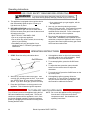
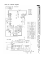
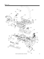
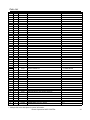
1
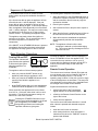
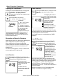
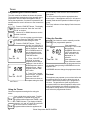
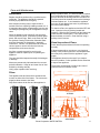
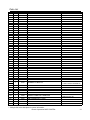
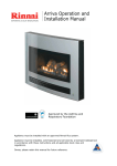
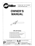
Owner’s Operation and Installation Manual for the
RHFE-750ETRA
Direct Vent Fireplace
Table of Contents........... 2
Safety Information .......... 2
Operating Instructions .... 6
Care and Maintenance ... 11
Fault Codes.................... 14
Installation Instructions .. 15
Consumer Support ......... 38
INSTALLER: Leave
this manual with the
appliance.
CONSUMER: Retain
this manual for future
reference.
WARNING: If the information in these instructions are not followed
exactly, a fire or explosion may result causing property damage,
personal injury or loss of life.
— Do not store or use gasoline or other flammable vapors and liquids in
the vicinity of this or any other appliance.
— WHAT TO DO IF YOU SMELL GAS
•
•
•
•
Do not try to light any appliance.
Do not touch any electrical switch; do not use any phone in your
building.
Immediately call your gas supplier from a neighbor’s phone. Follow
the gas supplier’s instructions.
If you cannot reach your gas supplier, call the fire department.
— Installation and service must be performed by a qualified installer,
service agency or the gas supplier.
This appliance may be installed in an aftermarket, permanently located, manufactured home
(USA only) or mobile home, where not prohibited by local codes.
This appliance is only for use with the type of gas indicated on the rating plate. This
appliance is not convertible for use with other gases, unless a certified kit is used.
Table of Contents
Consumer Safety Information
Safety Definitions ........................................ 2
Safety Behaviors and Practices.................. 3
Safety Features .......................................... 3
Specifications................................................. 4
Features ..................................................... 5
Dimensions ................................................. 5
Flue Manifolds ............................................ 5
Operating Instructions
Front Panel ................................................ 6
Remote Control Features ........................... 7
Remote Control Care .................................. 7
Sequence of Operations ............................. 8
Basic Fireplace Operations
Turning ON and OFF ............................. 8
Remote Control Operation .................... 8
Adjusting the Temperature .................... 9
Obstruction of Warm Air Discharge ....... 9
Lock Function ........................................ 9
Flame Function ...................................... 9
Auto Off Function................................... 9
Timers
Programming the Clock and Timers .... 10
Using the Timers ................................. 10
Using the Override............................... 10
Pre-heat ............................................... 10
Care and Maintenance
Maintenance ........................................ 11
Filters ................................................... 11
Visual Inspection of Flame .................. 11
Care of Exterior ................................... 12
Cleaning Combustion Chamber Glass 12
Troubleshooting ........................................ 13
Fault Codes .............................................. 14
Installation Instructions
General Instructions.................................. 15
Parts Included for Installation ................... 15
Clearances to Combustibles..................... 16
Flue Terminal Clearances .................. 16, 17
Location .............................................. 18, 19
Venting ................................................. 20-24
Venting with Flue Manifolds FOT-203
or FOT-204 .................................... 20-22
Extended Venting ........................... 22-24
Connections ........................................ 25, 26
Final Assembly
Install the Logs .................................... 27
Install Condensate Tray ...................... 28
Open the Air Guide Vanes .................. 29
Install the Front Panel ......................... 29
Operating Instructions .............................. 30
Wiring and Schematic Diagram ................ 31
Parts List .............................................. 32-37
Consumer Support ................................ 38, 39
Consumer Safety Information
Safety Definitions
This is the safety alert symbol. This symbol alerts you to potential hazards that can kill or hurt you and
others.
2
DANGER
Indicates an imminently hazardous situation which, if not avoided, will result in death or
serious injury.
WARNING
Indicates a potentially hazardous situation which, if not avoided, could result in death or
serious injury.
CAUTION
Indicates a potentially hazardous situation which, if not avoided, could result in minor or
moderate injury. It may also be used to alert against unsafe practices.
Rinnai Corporation RHFE-750ETRA
Safety Behavior and Practices
WARNING
• Keep the area around the appliance clear and free
from combustible materials, gasoline, and other
flammable vapors and liquids.
• Do not use this appliance if any part has been
under water. Immediately call a qualified service
technician to inspect the appliance and to replace
any part of the control system and any gas control
which has been under water.
• Do not operate appliance with the glass front
removed, cracked, or broken. Replacement of the
glass should be performed by a licensed or
qualified service technician.
• Never store liquid propane containers indoors.
• Young children should be carefully supervised
when they are in the same room as the appliance.
Toddlers, young children and others may be
susceptible to accidental contact burns. A physical
barrier is recommended if there are at risk
individuals in the house. To restrict access to a
fireplace or stove, install an adjustable safety gate
to keep toddlers, young children and other at risk
individuals out of the room and away from hot
surfaces.
• Broken or damaged components should be
removed or repaired by a licensed or qualified
service technician.
CAUTION
• Do not block the warm air discharge. Do not allow
anyone to sleep directly in front of the appliance.
• Due to high temperatures, the appliance should be
located out of traffic and away from furniture and
draperies.
• Children and adults should be alerted to the
hazards of high surface temperature and should
stay away to avoid burns or clothing ignition. Hand
or body contact with the warm air discharge louvers
and glass must be avoided.
• Young children should be carefully supervised
when they are in the same room as the appliance.
• Do not spray aerosols near the appliance while it is
operating. Most aerosols contain butane gas which
is flammable.
• Do not place items on or against the appliance. If
there is a power failure while the appliance is ON
then the overheat vent on top of the panel may
open to release internal heat. An item placed on
top of the appliance could prevent the overheat
vent from opening resulting in damage to the
appliance.
• Any safety filter or guard removed for servicing
must be replaced prior to operating the appliance.
• Clothing or other flammable material should not be
placed on or near the appliance.
• Do not insert items into the louvers.
Safety Features
• Overheat: The appliance will automatically shut
down when the appliance exceeds a predetermined
temperature.
• Power Surge Fuse: A glass fuse power supply
harness protects against overcurrent. If the fuse
blows then all indicator lamps will be off.
• Flame Failure: The appliance will automatically
shut down if the burner flame is extinguished.
• Spark Detector: The appliance automatically
shuts down if there is an abnormal spark at ignition.
• Power Failure: The appliance will cut off the gas if
it loses electrical power.
Rinnai Corporation RHFE-750ETRA
3
Specifications
Application
Vented gas fireplace heater; Inbuilt only; for residential installation, commercial setting, or manufactured home; not designed for installation in a solid-fuel
burning fireplace
Certification
CSA certified according to ANSI Z21.88, CSA 2.33
General Description
Inbuilt convector, glass and steel fronted, ceramic log space heater with
forced convection and power flue system
Operation
Push button electronic / remote control
Gas Connection
Flex line is 3/8 inch flare nut;
ball valve is 1/2 inch female x 3/8 inch flare
Gas Control
Electronic
Burners
Flame burners
Temperature Control
Electronic thermostat
Logs
Ceramic
Ignition System
Electronic spark ignition
Flue System
The flue must be terminated to atmosphere. Only flue components listed with
the appliance’s certification can be used. Warranty will be voided if non-listed
components are installed.
Electrical Connection
AC 120V, 60 Hz
Fan
(134 to 212 CFM)
Weight
150 lb (68 kg)
AFUE
79% NG; 81% LP (up to 83% with extended vent of 7.2 ft [2.2 m] and no
elbows)
Venting
Twin flue: maximum 6.5 ft with 2 elbows
Concentric: maximum 33 ft with 3 elbows
Natural Gas
Propane Gas
Minimum supply gas pressure
4.3 in (109 mm) W.C.
9.8 in (249 mm) W.C.
Maximum supply gas pressure
10.5 in (267 mm) W.C.
13.0 in (330 mm) W.C.
Manifold test pressure
Factory Set
Factory Set
BTU/hour input
Natural Gas: Low - 11,000 BTU/h; High - 29,000 BTU/h
Propane:
Low - 11,000 BTU/h; High - 28,000 BTU/h
BTU/hour output
Natural Gas: Low - 8,635 BTU/h; High - 21,900 BTU/h
Propane:
Low - 8,855 BTU/h; High - 21,840 BTU/h
Rinnai is continually updating and improving products. Therefore, specifications are subject to change without
prior notice.
4
Rinnai Corporation RHFE-750ETRA
Features
• Direct Vent: Intake air is taken from the outside
and the combustion products are exhausted to the
outside. Therefore the furnace has no effect on the
quality of the indoor air.
• Pre-heat: The appliance will turn on before the
programmed ON time and begin raising the room
temperature to that of the programmed temperature
by the ON time.
• Push Button Ignition: Only one push of the
STANDBY/ON switch is all that is required to
operate the heater.
• Memory: The computer memory records preset
temperatures, timer programming, and operational
modes.
• Lock: The buttons on the remote control can be
locked to prevent any unintended operation.
• Remote Control: The appliance has a fully
functioning cordless remote control.
• Dual Timer: The appliance can be programmed to
operate at two separate periods during the day.
• Auto-Off Function: You have the option of having
the flame display remain on or off once the room
temperature reaches the temperature setting.
Dimensions
inches (millimeters)
33 3/16 (842)
4 15/16 (126)
33 3/16 (842)
35 7/16 (900)
14 1/2 (369)
25 13/16 (655)
23 5/8 (600)
26 3/4 (679)
10 13/16 (274)
15 3/4 (400)
GAS CONNECTION
2 15/16 (71)
2 1/4 (57)
FLUE CONNECTION
14 7/8 (378)
21 5/16 - 23 5/16 (542 - 592)
B
B
27 9/16 (700)
Rinnai Corporation RHFE-750ETRA
3 5/16 (84)
17 13/16 (453)
5
Operating Instructions
Front Panel
OPERATION INDICATOR
TIMER INDICATOR
FAULT CODE DISPLAY
ON/OFF BUTTON
CONTROL PANEL
OVERHEAT
DISCHARGE VENT
LOG SET
TEMPERED GLASS IN THE
FRONT PANEL
CERAMIC GLASS PANEL AT
THE COMBUSTION CHAMBER
BLOCKAGE INDICATOR
for FILTERS (flashes red)
for WARM AIR DISCHARGE
(glows red)
REMOTE CONTROL
RECEIVER WINDOW
ROOM AIR RETURN
LOUVER, WARM
AIR DISCHARGE
Front Panel
(features are the same for flat and curved models)
Front Panel Models
6
Description
Part Number
Flat Metal - Black Front
R2700
Flat Metal - Stainless Steel Front
R2701
Radius (curved) Glass - Silver Front
R2702
Radius (curved) Glass - Black Front
R2703
Rinnai Corporation RHFE-750ETRA
Remote Control Features
INFRARED
EMITTER
DISPLAY
Lock OverrideAuto Off Flame
AM
PM
Temperature Time
Clock Set
Timer 1 Set ON OFF
Timer 2Set ON OFF
STANDBY / ON
BUTTON
Stops and operates the
heater remotely
STANDBY
ON
FLAME BUTTON
Controls the flame level
UP and DOWN
BUTTONS
Changes temperature,
flame level, or time
TIMER 1 BUTTON
Sets timer program 1
Timer 1
TIMER 2 BUTTON
Flame
Timer 2
Sets timer program 2
Auto
Off
Override
OVERRIDE BUTTON
Lock
Time
Set
AUTO
AUTO
OFFOFF
BUTTON
Turns the flame off when
the temperature setting is
reached.
Overrides timer
operation
LOCK BUTTON
TIME SET BUTTON
Locks out control to
prevent unintended
operation
Sets the clock and timers
Remote Control Care
• Use two 1.5V AAA batteries.
• To replace batteries unscrew the battery
compartment cover located on the back of the
remote control counter clockwise. Ensure that
the correct polarity is observed. The polarity is
engraved into the battery compartment.
Replace the cover by turning clockwise until a
soft click is heard.
• To avoid damage from leaking batteries,
remove batteries if the remote control is not
going to be used for a long period.
• Do not place it close to the warm air discharge
louvers.
• Avoid dropping the remote control or getting it
wet.
Celsius (0)/
Fahrenheit (1)
switch
1
0
O- I
• Some fluorescent lights may interfere with the
transmission of remote control signals.
• Avoid leaving the remote control in direct
sunlight.
Rinnai Corporation RHFE-750ETRA
7
Sequence of Operations
The combustion fan will run for several seconds
before ignition to purge the combustion chamber of
any gas.
If the front burner fails to ignite the appliance will turn
off and fault code 11 will be displayed. If the rear
burner fails to ignite the appliance will turn off and
make another attempt to ignite. If this second attempt
fails, the appliance will automatically turn off and fault
code 11 will be displayed. This may occur when using
the appliance for the first time or if it has not been
used for a while. Try operating the appliance again.
The appliance may make noises after ignition or
extinction of the flame. This is normal and is due to
the thermal expansion or contraction of its
components.
If the ON/OFF or the STANDBY/ON button is pressed
immediately after the flame has been extinguished,
the appliance will delay ignition for about 1 minute.
The normal ignition sequence is as follows:
1. When the ON/OFF or the STANDBY/ON button is
pressed the Operation Indicator LED will glow red
and the combustion fan will rotate to purge the
combustion chamber.
2. Electric ignitor operates.
3. Gas is allowed to flow to the pilot when a spark is
sensed.
4. When the pilot flame is established gas will flow to
the front burners and then to the rear burners.
5. When all burners are established the appliance
will automatically maintain the temperature
setting.
NOTE: The appliance will wait until the heat
exchanger is warmed up before discharging
air. This ensures that any discharge air will be
warm and not cold.
Basic Fireplace Operations
Turning ON and OFF
The Operation Indicator will
glow red when the appliance
is ON and will glow green
when the appliance is in
STANDBY.
Operation Indicator
The appliance will turn ON and attempt ignition:
•
when you press the ON/OFF button on the
appliance panel while the appliance is OFF.
•
when you press the STANDBY/ON button on the
remote control while the appliance is in
STANDBY.
•
at the TIMER setting after you have activated the
TIMER and while the appliance is in STANDBY.
When turned ON, the appliance will run at a flame
level of 5 for 1.5 minutes, after which it will run at its
last setting. This will be a temperature setting or a
flame level. See Flame Function.
STANDBY
ON
8
Pressing the STANDBY/ON button on the
remote control while the appliance is ON will
put the appliance in STANDBY mode,
extinguishing all flames and causing the
Operation Indicator to glow green.
Pressing the ON/OFF button while the appliance is
ON or in STANDBY will turn the appliance OFF. The
convection fan may continue to run for up to 15
minutes after the appliance has been turned OFF in
order to prevent the buildup of heat inside the
appliance.
Remote Control Operation
The remote control emits an infrared (IR) signal and
must be aimed at the receiver located to the right of
the warm air discharge louvers. The normal
operating range is about 16 feet (4.9 m) with an angle
of about 40 degrees to the horizontal. This range will
vary depending on the position of the installation and
the strength of the remote control batteries.
Signal transmissions are confirmed by
•
a brief illumination of the Transmission
Signal Indicator on the Remote Display
•
a flash by the Remote Control Receiver to the
right of the louvers
•
a beep from the appliance
The remote control transmits information 1 second
after a button is pressed and released except as
follows:
•
when the lock function is activated
•
when setting the timers, timer information is
transmitted only when the “TIME SET” button is
pressed and released
Rinnai Corporation RHFE-750ETRA
Basic Fireplace Operations
Adjusting the Temperature
Flame Function
Pressing the UP and DOWN buttons will change the
temperature setting by 2 degree (F)
increments. The display will show
“Temperature” and the new temperature as
confirmation.
The temperature can be set to:
•
L (Low) - burner is on minimum
combustion
Lock OverrideAuto OffFlame •
60° F - 80° F in two
degree increments
PM
Temperature
Clock Set
Timer 1 Set ON OFF
Timer 2 Set ON OFF
• H (High) - burner is
on maximum combustion
To use Celsius scale,
open the battery
compartment and move
the switch toward “0”.
The temperatures 16-26° C are available in one
degree increments. To return to Fahrenheit scale
move the switch toward “1”.
Obstruction of Warm Air Discharge
Obstructing the louvers for the warm air discharge will
cause the appliance to operate inefficiently.
When an obstruction is detected the Blockage
Indicator LED above the Receiver Window will glow
red and combustion reduces to front burner, low
operation only.
To restore normal operation, remove the obstruction,
turn the appliance OFF and then ON.
Lock Function
Lock
Pressing the LOCK button will cause all
functions of the remote control to be locked
except for the STANDBY/ON button.
Lock Override
AM
PM
Temperature Time
The remote control
display will show the word
“Lock” in the top left
corner.
To cancel the Lock
function press down and
hold the LOCK button for
3 seconds.
Press the FLAME button to control the flame
There are seven levels of flame
available.
Flame level.
The display will show the
word “Flame” and a series
Flame of short bars (one for each
flame level).
Lock Override
AM
PM
Temperature Time
Clock Set
Timer 1 Set ON OFF
Timer 2 Set ON OFF
Use the UP or DOWN
buttons to select the
desired flame level.
Pressing the FLAME
button again will allow the
appliance to control the
flame automatically.
If the room temperature reaches 104° F (40° C) while
the flame function is on then the appliance will turn off
automatically as a safety precaution.
The FLAME function is not available during TIMER
operation.
Auto Off Function
When the appliance is not in AUTO OFF
mode and the room temperature reaches
the temperature setting the appliance will
reduce the gas flow and
the flame on
Lock OverrideAuto Off Flame maintain
the lowest flame level.
AM
The temperature may
continue to rise even on
PM
this low setting. If the
Temperature Time
temperature reaches
Clock Set
104° F (40° C) then the
appliance will
Timer 1 Set ON OFF
automatically shut down
Timer 2 Set ON OFF
with fault code 16.
Auto
Off
When the temperature setting is reached while the
appliance is in AUTO OFF mode, the gas flow will be
reduced to pilot operation and the convection fan will
run on low speed. To enter this mode press the
AUTO OFF button. The words “Auto Off” will be
displayed above the time. To exit this mode press the
AUTO OFF again.
Whether this mode is on or off, the appliance will
attempt to maintain the temperature setting.
Rinnai Corporation RHFE-750ETRA
9
Timers
Programming the clock and timers
The clock must be set before the timers will operate.
The temperature setting during timer operation is the
temperature last used when the appliance was on.
During the steps below, if no button is pressed for 90
seconds then the screen will return to the current time
display.
Time
Set
1. Press the TIME SET button. The display
will show the words “Clock Set” and “AM
12:00” or the time.
go into standby mode and the Timer Indicator will
glow green.
To turn the timers off press the appropriate timer
button again. If the appliance was on, it will return to
standby mode and the Operation Indicator will glow
green.
The Timer Indicator will not display if both timers are
turned off.
2. Use the UP or DOWN buttons to set the
desired clock time.
NOTE: If you do not want to set the timers
now then press the TIME SET button five
more times to finish setting the clock.
3. Press the TIME SET button. “Timer 1
Set ON” and “AM 6:00” or
Lock OverrideAuto Off Flame the last programmed time
will be displayed. Use the
AM
UP or DOWN buttons to
set the desired on time.
Temperature Time
When finished press the
TIME SET button.
Clock Set
Timer 1 Set
Timer 2 Set
ON OFF
ON OFF
4. “Timer 1 Set OFF” and
“AM 9:00” or the last
programmed time will be
displayed. Use the UP or
Lock OverrideAuto Off Flame DOWN buttons to set the
desired off time. When
AM
finished press the TIME
PM
SET button.
Temperature Time
Clock Set
Timer 1 Set ON OFF
Timer 2 Set ON OFF
5. To set Timer 2 repeat
steps 3 and 4. If finished
press the TIME SET
button two more times to
complete setting the clock
and Timer 1.
Using the Timers
Using the Override
This function is used to manually override
Override Timer programmed operation.
If the appliance is
operating in Timer mode
then pressing
OVERRIDE will turn the
it OFF and cause the
word “Override” to be
displayed for 10
seconds.
Lock OverrideAuto Off Flame
AM
PM
Temperature Time
Clock Set
Timer 1 Set ON OFF
If the appliance is in
Timer mode but outside
Timer 2 Set ON OFF
of the programmed time
for operation then pressing OVERRIDE will turn the
appliance ON.
OVERRIDE does not change the programmed times.
Pre-heat
The appliance may operate up to one hour before the
programmed ON time in order to allow the room to
reach the desired temperature by the programmed
ON time. The pre-heat time (how long before the
programmed ON time that the appliance will provide
heat) is determined by the difference between the
temperature setting and the room temperature one
hour before the programmed ON time.
Check the temperature setting before using the
timers.
Timer 1
Timer 2
10
One or both timers can be used. To allow
the appliance to operate during the preprogrammed times press the TIMER 1 and/
or TIMER 2 button. The display will briefly
show the “on” and “off” times for each timer.
If the current time is outside of the
programmed times then the appliance will
Rinnai Corporation RHFE-750ETRA
Care and Maintenance
Maintenance
Repairs should be performed by a qualified service
technician. The appliance should be inspected
annually by a qualified service agency.
More frequent cleaning may be required due to
excessive lint from carpeting, bedding material, etc. It
is imperative that control compartments, burners, and
circulating air passage ways of the appliance be kept
clean.
When the appliance has cooled off, gain access by
removing the front panel, combustion chamber glass
panel, and ceramic logs. Refer to the Parts List and
the sections Cleaning Combustion Chamber Glass
and Final Assembly for disassembly / assembly
instructions. Vacuum, use pressurized air, and then
vacuum again to remove dust from the burners,
compartments, and convection fan.
Any filter or guard removed for servicing the
appliance must be replaced prior to operating the
appliance.
The vent should be inspected annually for blockages
or damage.
Motors are permanently lubricated and do not need
periodic lubrication. Keep fan and motor free of dust
and dirt by cleaning annually.
ability to produce heat. The filters should be cleaned
once a week during the heating season. If the filters
become blocked the blockage indicator will flash red.
The filters should be cleaned whenever the blockage
indicator flashes red. If not cleaned the appliance
may turn off and display fault code 14 (overheat) on
the control panel display.
To clean the filters, the appliance should be OFF and
cool. Open the louver by pushing inward and
releasing. Slide the filter upwards until the bottom tab
clears the lower retaining slot. Then slide the filter
down and away to remove. Clean the filter using a
soft dry cloth or vacuum.
Visual Inspection of Flame
Check that the pilot and burner flames are operating
normally.
If flames appear either very short or very long and
streaky or are producing smoke or soot deposits then
there may be a problem with the appliance or gas
supply.
The appliance should not be used if you suspect
there is a problem. Call a qualified service technician
to inspect the appliance.
The burners are designed to produce two rows of
yellow flame but not smoke or soot.
Verify proper operation after servicing.
Filters
This appliance has two filters which are behind the
louvers on either side of the heater. The louvers are
hinged to allow access to the filters.
Dirty filters reduce the air flow and the appliance’s
NORMAL
ABNORMAL
Rinnai Corporation RHFE-750ETRA
11
Care and Maintenance
The pilot flame should be blue and extend over the
flame rod from half to three-fourths of its length. It
should not be long, streaky, or yellow.
2. Remove two screws attaching the front panel to
the appliance.
CORRECT PILOT FLAME APPEARANCE
3. Remove the front panel by rotating the bottom
away from the appliance and lifting upwards to
unhook the panel from the top of the appliance.
unhook top
Front Panel
Cleaning Combustion Chamber Glass
Over time combustion products may leave a film on
the combustion chamber glass. Continued use of the
appliance may permanently stain the glass. If filming
occurs, this glass panel needs to be removed,
cleaned, and installed only by a qualified service
technician.
rotate
outward
first
WARNING
Do not clean glass when hot.
Do not clean glass with abrasive cleaners.
1. Open the side louvers and on each side remove
one screw attaching the top panel. (Side louvers
are opened by pushing in and releasing.)
4. Remove two retaining screws and remove the
combustion chamber glass panel.
5. Clean using non-abrasive, non-solvent household
cleaner.
6. Install the glass panel. Refer to Final Assembly.
7. Install the front panel with two screws through the
louvers. Refer to Final Assembly.
8. Install the top panel with one screw on each side
of the side louvers. Refer to Final Assembly.
Care of Exterior
Clean exterior as required using non-abrasive and
non-solvent cleaner. Ensure exterior is completely
dry before operating.
12
Rinnai Corporation RHFE-750ETRA
Troubleshooting
Problem
Possible Solutions or Explanation
No display on remote
Replace the remote control batteries.
No ignition or no panel indications
Ensure the appliance has power.
Press the control panel ON/OFF button.
Burners fail to ignite
Air may need to be purged from the gas line. Several
ignition attempts may purge the gas line.
Turn on the gas supply.
Combustion stops during operation
Remove any obstructions from the louvers.
Turn on the gas supply.
Smell of gas
Follow the instructions in the warning block on the front of
this manual.
Remote control does not work
Ensure the appliance has power.
Press the control panel ON/OFF button.
Press the LOCK button for 3 seconds if LOCK is displayed.
Press the STANDBY/ON button.
Warm air does not start immediately after burner
lights
The appliance will wait until the heat exchanger is warmed
up before discharging air. This ensures that any discharge
air will be warm and not cold.
Smoke or odors are produced when first operated
This is caused by grease or oil on the heat exchanger or by
dust and should stop after a short time.
Clicking noises at ignition or shutdown
Internal components are cooling (contracting) or heating up
(expanding) at different rates.
Clunking noise when the thermostat operates
This is the sound of the solenoid gas valves opening and
closing to regulate the gas flow.
Convection fan continues to run after appliance is
turned OFF
The fan will continue to run to prevent internal components
from overheating.
Steam is discharged from the flue outside
Steam discharge is normal.
Does not start while in STANDBY and the
temperature is below the setting
Timers must be turned off (or press OVERRIDE) for
manual operation.
Timers do not turn the appliance ON or OFF
Timers may be turned off or incorrectly programmed.
Timer turns the appliance ON briefly and then the
appliance turns OFF before the OFF time setting.
The room temperature may be higher than the temperature
setting.
Rinnai Corporation RHFE-750ETRA
13
Fault Codes
If there is a malfunction the appliance may shut down as a safety precaution and display a fault code to assist in
diagnosing the problem. The fault code will flash in the Fault Code Display window and the Operation Indicator
will flash green.
Code
Fault
Remedy
11
Ignition failure
Confirm that the gas supply is turned on. Switch appliance to
STANDBY and then ON again. If ignition failure continues
then a Service call is required.
12
Incomplete combustion
Service call
14
Filter blocked or Overheat
Clean filters
If overheating continues then a service call is required to
determine the cause.
Thermal fuse; a qualified service technician must replace the
fuse following the procedure below.
16
Room overheat
The temperature has reached 104° F (40° C). Turn the
appliance off or engage the AUTO OFF function to prevent the
display of flame. See AUTO OFF section.
31
Room temperature sensor faulty
Service call
32
Overheat temperature sensor 2 faulty Service call
33
Overheat temperature sensor 1 faulty Service call
49
Flue block sensor faulty
Service call
53
Spark sensor faulty
Service call
61
Fan motor faulty
Service call
71
Solenoids faulty
Service call
72
Flame detection circuit fault
Service call
73
Communication fault
Service call
99
Flue block
Check around flue terminal for obstructions to air flow
Replacement of Thermal Fuse
The cause of the overheat condition needs to be
determined and remedied before replacing the
thermal fuse.
Thermal Fuse
PCB
A qualified service technician needs to:
1. Disconnect the appliance from the power supply.
2. Remove the right hand side panel to allow access
to the gas control and main PCB.
3. Unplug the thermal fuse harness (including the
control plug for the POV on the gas control) and
unscrew thermal fuse.
4. Re-assemble with replacement thermal fuse.
14
Rinnai Corporation RHFE-750ETRA
POV
Installation Instructions
General Instructions
The appliance must not be connected to a chimney
flue serving a separate solid-fuel burning appliance.
WARNING
Do not use substitute materials.
Use only parts certified with the appliance.
A qualified service technician should install the
appliance and inspect it before use.
The installation must conform with local codes or, in
the absence of local codes, with the National Fuel Gas
Code, ANSI Z223.1/NFPA 54, or the Natural Gas and
Propane Installation Code, CSA B149.1.
A manufactured home (USA only) must conform with
the Manufactured Home Construction and Safety
Standard, Title 24 CFR, Part 3280, or, when such a
standard is not applicable, the standard for
Manufactured Home Installations, ANSI/NCSBCS
A225.1, or the standard for Gas Equipped
Recreational Vehicles and Mobile Housing, CSA
Z240.4.
The appliance, when installed, must be electrically
grounded in accordance with local codes or, in the
absence of local codes, with the National Electrical
Code, ANSI/NFPA 70, or the Canadian Electrical
Code, CSA C22.1.
Two 1/8 in test plugs are provided for testing of
manifold differential pressure.
The appliance and its appliance main gas valve must
be disconnected from the gas supply piping system
during any pressure testing of that system at test
pressures in excess of 1/2 psi (3.5 kPa).
The appliance must be isolated from the gas supply
piping system by closing its equipment shutoff valve
during any pressure testing of the gas supply piping
system at test pressures equal to or less than 1/2 psi
(3.5 kPa).
If the flooring is carpet, tile, or other combustible
material other than wood, then the appliance must be
installed on a metal or wood panel extending the full
width and depth of the appliance.
This appliance discharges a large volume of warm air
next to the floor. Any particles in the air such as
cigarette smoke could cause discoloration in carpet.
The warm air flow could discolor nylon carpets
containing dyes or vinyl surfaces. To prevent
discoloration of the floor covering place a mat under
the appliance which extends about 30 inches in front
of it.
Refer to the conversion manual for high altitude
installations.
Parts Included for Installation
The appliance and front panel are packaged separately. The top panel is included with the front panel.
Confirm that the following parts are included with the appliance:
•
Operation and Installation Manual
•
Conversion Manual
•
remote control
•
remote control holder
•
2 AAA batteries
•
log set (7 pieces)
•
ball valve (on/off valve for gas line)
•
plastic cable tie (for securing the air intake hose to
the flue manifold)
•
power cord flex clamp (for securing electrical
connection at the junction box)
•
flue clamp (for securing the exhaust line to the flue
manifold)
•
3 screws (2 long screws for the remote control
holder and 1 short screw for the flue clamp)
•
condensate tray
Rinnai Corporation RHFE-750ETRA
15
Clearances to Combustibles
The clearances to combustibles as stated on the
rating plate and as shown in the figures must be
followed. Also refer to the Safety Behaviors and
Practices section.
5”
Clearances for a
mantle or
decorative
overhang
4”
45
3”
Interior
wall
2”
1”
Clearance from concentric vent system: zero in/mm
3” Minimum
Side clearances for air vents
Interior wall
1”
2”
3”
4”
3” Minimum
Top view
5”
45º
Side view
Flue Terminal Clearances
TERMINATION
INSIDE
CORNERDETAIL
Clearance in
Ref. A also
applies to
anticipated
snow line
G
H
A
SNOW
I
B
D
FIXED
CLOSED
B
K
OPERABLE
E
C
B
B
FIXED
CLOSED
J
B
A
OPERABLE
L
F
B
16
M
Rinnai Corporation RHFE-750ETRA
X
AIR SUPPLY INLET
V
VENT TERMINAL
AREA WHERE
TERMINAL IS NOT
PERMITTTED
Flue Terminal Clearances
Ref
Description
Canadian Installations
US Installations
A
Clearance above grade, veranda, porch,
deck, or balcony. (Take into account the
anticipated snow line.)
12 inches (30 cm)
12 inches (30 cm)
B
Clearance to window or door that may be
opened
12 inches (30 cm)
9 inches (23 cm)
C
Clearance to permanently closed window
*
*
D
Vertical clearance to ventilated soffit,
located above the terminal within a
horizontal distance of 2 feet (61 cm) from
the center line of the terminal
*
*
E
Clearance to unventilated soffit
*
*
F
Clearance to outside corner
*
*
G
Clearance to inside corner
*
*
H
Clearance to each side of center line
extended above meter/regulator assembly
3 feet (91 cm) within a
height 15 feet (4.57 m)
above the meter/
regulator assembly
*
I
Clearance to service regulator vent outlet
3 feet (91 cm)
*
J
Clearance to nonmechanical air supply
inlet to building or the combustion air inlet
to any other appliance
12 inches (30 cm)
9 inches (23 cm)
K
Clearance to a mechanical air supply inlet
6 feet (1.83 m)
3 feet (91 cm) above if
within 10 feet (3 m)
horizontally
L
Clearance above paved sidewalk or
paved driveway located on public property
7 feet (2.13 m) 1
*
M
Clearance under veranda, porch, deck, or
balcony
12 inches (30 cm) 2
*
1 A vent shall not terminate directly above a sidewalk or paved driveway that is located between two single
family dwellings and serves both dwellings.
2 Permitted only if veranda, porch, deck, or balcony is fully open on a minimum of two sides beneath the floor.
*
For clearances not specified in ANSI Z223.1/NFPA 54 or CSA B149.1, clearances are in accordance with
local installation codes and the requirements of the gas supplier.
Rinnai Corporation RHFE-750ETRA
17
Location
This appliance has a cool outer casing that allows it to
be installed in a recessed application consisting of
combustible materials such as wood and plaster.
The location needs to have a level surface that allows
the appliance to be rolled in or out of the enclosure.
If the surface is elevated and there is not enough
room for it to be rolled out then a base and joists may
be used as shown.
The appliance will have to be rolled out for
maintenance. After installation do not place any
permanent fixtures that would prevent pulling the
appliance out for access. To pull the appliance
completely out of the enclosure a minimum of 15
inches from the front panel would be needed.
LEFT
WHEEL
RIGHT
WHEEL
JOIST
JOIST
28.3 in (720 mm)
Do not vent the exhaust into ‘natural draft’ flue pipes
or a chimney flue.
w
The enclosure must be within these limits:
Enclosure Dimensions
Width (w)
33.8 in (860 mm)
Height (h)
26.0 - 26.2 in (660-665 mm)
Depth (d)
15.0 - 16.9 in (380-430 mm)
h
NOTE: These are minimum clearances.
d
The front panel extends below the surface on which
the appliance rests. Ensure that clearance is
maintained in order to install the front panel.
For installation in the corner of the room refer to the
diagram at the right and the table below for
dimensions. These dimensions are the minimum
required if using the minimum width, height, and
depth dimensions above.
Enclosure Dimensions in a Corner
x
63.8 in (1620 mm)
y
45.1 in (1146 mm)
z
31.9 in (810 mm)
x
y
z
18
Rinnai Corporation RHFE-750ETRA
Location
Wall Lining
Use the adjustment feet so that the appliance is level
and not tilted. They are initially installed immediately
behind the side louvers but can be moved forward for
better access in hearth or floor installations.
The hearth should not block the appliance from being
rolled out nor should it prevent the front panel from
being installed or removed.
Correct Floor
Level Installation
Adjustment
feet
Floor (Timber, Concrete, Tile, etc.)
Correct Hearth
Installation
Hearth
Correct In-wall
Installation
Adjustment
feet
Adjustment
feet
Wall Lining
Particle Board, MDF, Plywood etc.
Wall Lining
Particle Board, MDF, Plywood etc.
Incorrect Hearth
Installation
Incorrect Hearth
Installation
Hearth
Adjustment
feet
Wall Lining
Particle Board, MDF, Plywood etc.
Rinnai Corporation RHFE-750ETRA
Hearth
Adjustment
feet
Wall Lining
Particle Board, MDF, Plywood etc.
19
Venting
There are 2 categories for venting:
I.
Venting with Flue Manifolds FOT-203 or FOT-204 - horizontal venting directly through the wall with no
extensions.
II. Extended Venting - horizontal and vertical terminations with a maximum 33 feet and 3 elbows.
I.
Venting with Flue Manifolds FOT-203 and FOT-204
The following flue manifold sizes are available:
Name
Kit No.
fits walls
Vent Kit A
FOT-203
4 1/3 - 9 1/2 inch
(110 - 240 mm)
Vent Kit B
FOT-204
9 1/2 - 15 3/4 inch
(240 - 400 mm)
FOT-203 /
FOT-204
Flue extensions are not authorized to be used with
the FOT-203 and FOT-204 manifolds.
Drilling Flue and Gas Supply Holes
Check for water and gas pipes as well as electric
cables. Use the template supplied to mark the wall
locations for the flue manifold and the gas supply.
Drill the flue hole using a 3 1/2 inch (90 mm) drill.
For weatherboard walls, drill through the center of the
weatherboard from the outside first and then through
the plasterboard.
Flue Manifold Installation
1. Disassemble the Flue Manifold
The flue consists of 3 parts:
Inside Connection
• sleeve
Terminal
• inside connection
• terminal
Disassemble the flue manifold by first pulling
out the inside connection. To remove the
outer terminal pull and release the two
internal ties and then pull out the outer
terminal.
Clearance to combustibles for the sleeve and
flanges is zero inches.
20
Rinnai Corporation RHFE-750ETRA
Sleeve
Venting
2. Assemble and Adjust the Sleeve Length
Measure wall thickness through previously drilled
3 1/2 inch (90 mm) hole.
The end of the sleeve should protrude 3/16 - 3/8
inch (5-10 mm) from the outside wall.
In the FOT-203 (Vent Kit A) there are 4 parts
provided with which to assemble the sleeve. Use
the table to determine which pieces to assemble.
In both kits, two parts are threaded for additional
adjustment.
Adjust the sleeve length to wall thickness plus
3/16 - 3/8 inch (5-10 mm).
For wall thickness plus 3/16 - 3/8 in (5-10 mm)
Sleeve Parts
Assemble these parts (“A” Vent Kit)
4 1/3 - 6 1/8 in (110 - 155 mm)
6 1/8 - 7 3/4 in (155 - 195 mm)
7 3/4 - 9 1/2 in (195 - 240 mm)
c
b
a
a
a
+
b
a
+
b
+
c
+
b
+
c
+
3. Attach the sleeve
c
sleeve should extend
3/16 - 3/8 in (5-10 mm)
Attach to the inside wall using 3 screws arranging
the flange so that the marking “TOP” is at the top.
The flange is offset 2° to allow the condensate to
drain to the outside.
3 screws
4. Install the Terminal
Check that the terminal seal is in place. For
weatherboard or vinyl siding, add the second seal
next to the terminal seal to compensate for the
angle.
Terminal seal
From the outside insert the terminal into the
sleeve with the marking “TOP” at the top. The left
hand side locking tie should be marked “LEFT”.
Terminal
Locking tie
Rinnai Corporation RHFE-750ETRA
21
Venting
5. Lock the ties
Locking ties
Pulling hard on the left and right hand ties, clip
the ties over the notches inside the sleeve. You
should be able to pull the ties 2 or 3 notches past
the starting point. Cut the ties, leaving about 3/4
inch (20 mm) past the notch. Bend the ties back
into the sleeve and parallel to the wall.
Sleeve
6. Attach Inside Connection Assembly
Push the assembly into the terminal tube.
Attach the inside connection with 3 screws. The
inside connection can still be turned if necessary.
II. Extended Venting - Horizontal and Vertical Terminations
•
Only vent components that are certified and listed
with this appliance may be used.
•
The maximum length is 33 feet (10 m) with a
maximum of 3 elbows.
•
The venting length (horizontal and vertical) that is
draining back toward the appliance is limited to
8.2 feet (2.5 m). A condensate collector must be
installed at this point if more venting length is
needed. Dispose of condensate per local codes.
The condensate trap must contain a minimum of 3
inches (75 mm) of water.
•
Vent diameter must not be reduced.
•
Do not connect the venting system with an
existing vent or chimney.
•
Do not common vent with the vent pipe of any
other appliance.
•
The horizontal termination must not be used as a
vertical termination; the vertical termination must
not be used as a horizontal termination.
•
Slope any horizontal venting 1/4 inch per foot (19
mm / m), towards the outside so that it can drain
out of the termination -OR- slope 1/4 inch per foot
(19 mm / m), toward the appliance which has a
condensate tray.
For vertical venting, an additional 2 inch elbow,
part number 308000010, is required and available
from Rinnai for connecting the exhaust to the
adapter.
•
Refer to the instructions of the vent system
manufacturer for component assembly
instructions.
•
Do not combine vent components from different
manufacturers.
•
•
The vent system must vent directly to the outside
of the building and use outside air for combustion.
•
If the vent system is to be enclosed, it is
suggested that the design of the enclosure shall
permit inspection of the vent system. The design
of such enclosure shall be deemed acceptable by
the installer or the local inspector.
Venting should be as direct as possible with a
minimum number of pipe fittings.
•
Avoid dips or sags in horizontal vent runs by
installing supports per the vent manufacturer’s
instructions.
•
•
22
Support horizontal vent runs every four feet and
all vertical vent runs every six feet or in
accordance with local codes.
NOTICE
If it becomes necessary to access an enclosed vent
system for service or repairs, Rinnai is not responsible
for any costs or difficulties in accessing the vent
system. Warranty does not cover obtaining access to
an enclosed vent system.
Rinnai Corporation RHFE-750ETRA
Venting
Certified and Listed Vent Products
Maximum Length = 33 feet (10 m) and 3 elbows
Manufacturer: Metal-Fab
Product: Corr/Guard
Part
Number
Description
3CGRFA
Adapter
3CGDS
Condensate Collector
3CGRVT
Vertical Termination
3CGRHT
Horizontal Termination
3CG6
6” Vent Pipe Extension
3CG12
12” Vent Pipe Extension
3CG18
18” Vent Pipe Extension
3CG24
24” Vent Pipe Extension
3CG36
36” Vent Pipe Extension
3CGRHA
90 Degree Vent Pipe
Elbow
VERTICAL
TERMINATION,
3CGRVT
VENT PIPE
EXTENSION
CONDENSATE
COLLECTOR,
3CGDS
2 inch elbow,
308000010,
available from
Rinnai
Maximum Length
draining back to
appliance without a
Condensate Collector =
8.2 feet (2.5 m)
90 DEGREE VENT PIPE
ELBOW, 3CGRHA
NOTICE
Installations depicted are examples of
configurations only and exclude
brackets, flashing, trim, and other
accessories required for a complete
installation.
HORIZONTAL
TERMINATION,
3CGRHT
ADAPTER,
3CGRFA
Sloped toward
appliance to prevent
condensate collecting
in the elbow.
Follow the guidelines on the opposite
page and follow the Metal-Fab
installation instructions for installing the
venting.
Refer to the Metal-Fab direct vent
system components catalogue to
determine the parts required for you
particular vent application.
Rinnai Corporation RHFE-750ETRA
23
Venting
Additional Venting Clearances
The top of the vertical termination should not be less
than 18 inches from the storm collar.
Refer to the instructions of the vent system manufacturer
for complete component assembly instructions.
Horizontal Vent Termination
Wall
The distance between the
wall and the air inlet cover
should be 1.0 - 2.36 inches
(25 - 60 mm)
Vent Length Switch
If using extended venting, move
the dip switch in the control panel
to L-F.
24
Vent Length Switch
Rinnai Corporation RHFE-750ETRA
Connections
1. Carefully remove the packaged ceramic logs and
place in a safe location.
2. To ensure the correct positioning, terminate the
gas supply so that it is 5.9 inches (150 mm) from
the front of the enclosure.
6. Unscrew the flue access panel held by two
screws located inside the top left hand corner of
the appliance. Slide this panel to the right behind
the convection fan.
3. Gain access to the gas connection by removing
the right hand side access panel and by
unscrewing the four retaining screws. Pry the
front edge of the panel open to the right and pull
forwards.
4. Position the appliance in front of the enclosure so
that the end of the gas supply aligns with the gas
fitting opening. Connect the flexible gas
connection to the gas supply.
5. Replace the right hand panel and secure with the
four retaining screws.
remove 4
screws to
remove
side
panel
7. Remove the 2 screws attaching the cover on the
junction box. Install the power cord flex clamp by
inserting the threaded part through the bottom
hole and attaching the washer. Attach the
electrical connection and place in the junction
box. Attach the cover with 2 screws.
8. Leak test the gas connection using a soapy
solution. Do not allow the soapy solution to
contact electrical components. Remove any
residue.
gas connection
gas fitting opening
Rinnai Corporation RHFE-750ETRA
25
Connections
9. Remove clamp L and slide the vertical pipe M
down into the lower elbow N to remove parts J
and K. Separate J and K.
J
13. Slide tube M up into elbow K and clamp together
with clamp L.
K
L
14. Slide the flue access panel back into position and
attach with two screws. This panel may be
turned upside down to allow for a different flue
pipe height.
15. Open both of the air return louvers on both sides.
Secure the appliance using the four mounting
points.
M
4 mounting points
N
10. Attach pipe J to the flue manifold (or the adapter
or the 2 inch elbow for extended venting) with
clamp and screw.
11. Push the air intake line onto the flue manifold or
adapter and secure with the plastic cable tie.
Make sure the hose does not kink.
Tie
Air Intake Line
Clamp
Pipe J
12. Carefully slide the appliance into the enclosure
lining up the gas supply and exhaust pipe. Fit
elbow K to pipe J making sure that the clip in
elbow K goes beyond the groove in the pipe. The
gas supply flexible hose is designed to coil inside
the appliance as it is pushed into the enclosure.
26
Rinnai Corporation RHFE-750ETRA
Final Assembly
Install the Logs
The log set consists of seven pieces as follows:
• rear
• right hand top
• left hand middle
• left hand front
• right hand middle
• right hand front
rear
Step 3
• center top
1. Remove the two retaining screws that secure the
combustion chamber glass panel.
2. Rotate and lift the combustion chamber glass clear
of the combustion chamber and place in a safe
location.
retaining screws
locating pins
left hand middle
right hand middle
Steps
4&5
J
locating pins
center top
right hand top
3. Seat the rear log into the combustion chamber
onto its location pins.
4. Seat the left hand middle log onto its location pins.
Steps
6&7
5. Seat the right hand middle log onto its location
pins.
6. Seat the center top log onto the location pins.
7. Seat the right hand top log onto the location pins.
8. Place the left hand front log and the right hand
front log on the pins.
9. Install the glass panel with two retainer screws at
the top of the panel.
locating pins
left hand front
right hand front
Step 8
Rinnai Corporation RHFE-750ETRA
27
Final Assembly
Ensure that the sealing material completely covers
the perimeter of the glass. Squeeze the sealing
material so that it is no longer flat. This will allow it
to flatten correctly when installed.
Correct
WARNING
Installing Glass Panel
Ensure that the lower slots are properly positioned
against the combustion chamber. The slot should be
between the tapered washer and the appliance; it
should not be between the tapered washer and the
spring.
Incorrect
Correct
Incorrect
Condensate Tray
Place the condensate tray on top of the lower panel
on the left side under the condensate tube.
Place it flat so that it matches up with the shape of the
lower panel. One edge of the tray has a short lip.
Position the tray so that this lip is towards the front of
the appliance.
Condensate tray
Front of appliance
Lower panel
Condensate tray
28
Rinnai Corporation RHFE-750ETRA
Lower panel
Final Assembly
Air Guide Vanes
Install the Front Panel
To move the air flow more to the right or to the left,
bend the air guide vanes using only light hand
pressure.
1. Install the front panel by hooking the top into the
body and rotating the bottom towards the
appliance.
Hook top first
Do not bend repeatedly (no more than 5 times) or
else the vane will break.
Front Panel
then rotate
inward
2. Secure the front panel to the appliance using
two screws through the front of the warm air
discharge louvers.
3. Set the top panel into place. Open the side
louvers and on each side attach the top panel with
one screw. (Side louvers are opened by pushing
in and releasing.)
Rinnai Corporation RHFE-750ETRA
29
Operating Instructions
FOR YOUR SAFETY READ BEFORE OPERATING
WARNING
If you do not follow these instructions exactly, a fire or explosion
may result causing property damage, personal injury or loss of life.
A. This appliance is equipped with an ignition device
that automatically lights the pilot. Do not try to
light the burner by hand.
B. BEFORE OPERATING smell all around the
appliance area for gas. Be sure to smell next to
the floor because some gas is heavier than air and
will settle on the floor.
WHAT TO DO IF YOU SMELL GAS
• Do not try to light any appliance.
• Do not touch any electric switch; do not use any
phone in your building.
• Immediately call your gas supplier from a
neighbor’s phone. Follow the gas supplier’s
instructions.
• If you cannot reach your gas supplier, call the
fire department.
C. Use only your hand to push the gas control
buttons. Never use tools. If the knob will not push
in or turn by hand, don’t try to repair it, call a
qualified service technician. Force or attempted
repair may result in a fire or explosion.
D. Do not use this appliance if any part has been
under water. Immediately call a qualified service
technician to inspect the appliance and to replace
any part of the control system and any gas control
which has been under water.
OPERATING INSTRUCTIONS
1. STOP! Read the safety information above.
Error Code
On/Off Button
4. If the appliance does not light it will automatically
shut down and an error code will display. Check
this manual for error code definitions.
5. To re-attempt ignition, press the On/Off button
twice.
6. To adjust the heat, press the up▲ or down▼
buttons on the remote control to adjust the
thermostat.
7. To turn the unit off, press the On/Off button on the
top control panel.
2. Wait five (5) minutes to clear out any gas. Then
smell for gas, including near the floor. If you smell
gas, STOP! Follow “B” in the safety information
above. If you don’t smell gas, go to the next step.
8. If the appliance will not operate, follow the
instructions “To Turn Off Gas To Appliance” and
call your service technician or gas supplier. See
this manual for additional information.
3. Press the On/Off button on the top panel on the
appliance. This will start the ignition sequence.
TO TURN OFF GAS TO APPLIANCE
Turn off electric power to the appliance using the On/
Off button located on the control panel. The fan will
continue to operate until the appliance is cool. Once
the fan has stopped operating, isolate the appliance
power by unplugging it from the wall or turning off the
isolating breaker switch.
30
NOTE: Do not turn the appliance off by unplugging it
from the wall. Keep burner and control
compartment clean. See installation and
operating instructions.
Rinnai Corporation RHFE-750ETRA
Wiring and Schematic Diagrams
CAUTION
Label all wires prior to disconnection when servicing controls.
Wiring errors can cause improper and dangerous operation.
If any of the original wire as supplied with the
appliance must be replaced, it must be replaced with
type 18 AWG wire or its equivalent.
31
Rinnai Corporation RHFE-750ETRA
Parts List
For replacement parts call Rinnai at 1-800-621-9419.
32
Rinnai Corporation RHFE-750ETRA
Parts List
Rinnai Corporation RHFE-750ETRA
33
Parts List
131
120
100
104
105
119
103
132
118
80
117
101
134
106
97
124
108
125
107
98
99
110
122
116
126
49
114
99
98
101
113
128
111
115
121
112
109
127
123
133
118
74
115
129
123
102
120
117
34
Rinnai Corporation RHFE-750ETRA
123
130
Parts List
ITEM
1
2
3
4
5
6
7
8
9
10
11
12
13
14
15
16
17
18
19
20
21
22
23
24
25
26
27
28
29
30
31
32
33
34
35
36
37
38
39
40
41
42
43
44
44
45
45
46
47
47
QTY
1
2
1
1
2
2
2
1
1
1
1
2
2
1
1
1
1
1
1
1
1
1
1
1
1
1
1
1
1
PART NO.
10201
10777
2
10752
1
1
2
2
1
1
1
1
1
3
2
1
2
2
1
1
1
1
1
10750
10782
10783
10784
10785
10786
10418
10255
10226
10462
10753
10754
7185
5436
5425
5548
10413
10275A
10277A
10458
10751
10778
10232
10231
10742Z
10780
10390
10224Z
10204
10427
10431
10432
10208
10205
10206
10263
10264
10781
10213
10869
10207
10296Z
10297Z
DESCRIPTION
COMMENTS
PANEL BASE RHFE750ETR
FOOT KIT RHFE
BRACKET COMB CHAMBER SUPPORT RH R750
NON SERVICEABLE PART
BRACKET COMB CHAMBER SUPPORT LH R750
NON SERVICEABLE PART
BRACKET FRONT MOUNT RHFE
WHEEL KIT RHFE750/IBOF
GLASS RETAINER SPRING KIT RHFE750
PANEL AIR DIVERTER RH RHFE750
PANEL AIR DIVERTER LH RHFE750
PANEL AIR GUIDE LOWER US BLACK
COMBUSTION CHAMBER ASSEMBLY PAINTED R750 NON SERVICEABLE PART
GLASS RETAINER SLIDE ASSEMBLY RHFE750
GLASS RETAINER SLIDE COVER RHFE750
PANEL BURNER SHIELD PAINTED R750
PANEL HEAT SHIELD REAR RHFE750
PANEL HEAT SHIELD RH RHFE750
PANEL HEAT SHIELD LH RHFE750
PANEL COMB FAN FLUE DIVIDER
PANEL FAN INFILL RHFE750
PANEL OUTER RH RHFE750ETR
PANEL OUTER LH RHFE750ETR
PANEL COMB FAN INLET "A"
PANEL REAR AIR INLET "B"
COMBUSTION FAN COVER RHFE750
PANEL COVER FLUE OUTLET
PANEL COVER TRANS RHFE
TOP PANEL RHFE ENGINE ASSEMBLY
LOUVER SIDE SUPPORT RH BLACK 750
LOUVER SIDE SUPPORT LH BLACK 750
LOUVER HINGE KIT
DOOR LATCH KIT
COMB CHAMBER GLASS ASSEMBLY RHFE750
LOUVER SIDE ASSEMBLY RHFE750
SCREEN KIT RHFE750
WAX ELEMENT ASSEMBLY RHFE750
MAIN PCB BRACKET ASSEMBLY RHFE750
BRACKET REAR BURNER SUPPORT RHFE
BRACKET RECEIVER RHFE750
BRACKET INJECTOR SUPPORT RHFE750
PACKING INJECTOR BLOCK
INJECTOR BLOCK KIT REAR RHFE750
INJECTOR BLOCK KIT FRONT RHFE750
INJECTOR 1.45
INJECTOR 0.9
INJECTOR 1.75
INJECTOR 1.05
BRACKET TRANSFORMER MOUNT RHFE
BURNER BRAY 450 NG + BUSH
BURNER BRAY 450 LP Ø5.0
KIT CONTAINS 1 x UPPER AND
1 x LOWER HINGE
CONTAINS 4 x LATCHES
NG **
LPG **
NG **
LPG **
NG **
LPG **
** Always refer to the data plate for correct information.
Rinnai Corporation RHFE-750ETRA
35
Parts List
ITEM
48
48
48
49
QTY
2
1
1
1
PART NO.
10359F
10359B
10359G
10764
DESCRIPTION
BURNER ASSEMBLY BRAY 250 Ø3.0 x 2
BURNER ASSEMBLY BRAY 250 Ø6.0 x 2
BURNER ASSEMBLY BRAY 250 Ø6.5 x 2
PILOT ASSEMBLY RHFE750
50
1
10772
PILOT ELECTRODE KIT RHFE750
51
52
53
54
54
1
1
1
1
1
10419
10212
10549
10760
10761
BRACKET REAR BURNER CLAMP RHFE
PANEL BURNER SURROUND REAR BLACK
PANEL BURNER SURROUND FRONT BLACK
AERATION PLATE SET RHFE750 NG US
AERATION PLATE SET RHFE750 LPG US
55
1
10757
LOG PIN SET RHFE US
56
57
58
58
59
60
60
61
62
62
63
64
65
66
67
68
69
70
71
72
73
74
75
76
77
78
79
80
81
82
83
84
85
86
87
88
89
1
2
1
1
1
1
1
1
1
1
1
1
1
1
1
1
1
1
10215
10211
7795
7873
10272
10425
10426
10430
10787
10788
10267
6313
10441
10248
10247
10249A
10249B
10520
1
1
1
1
1
1
1
1
1
1
1
1
1
1
1
1
1
COMMENTS
NG LEFT AND RIGHT **
LPG LEFT ONLY **
LPG RIGHT ONLY **
INCLUDES DOUBLE
ELECTRODE, FLAME ROD AND
CLAMPS
NG **
LPG **
6 x LONG PINS + SCREWS
4 x SHORT SCREWS
PANEL AIR INLET COVER RHFE750
BRACKET BURNER EXP PLATE RHFE750
INJECTOR NG 62
INJECTOR NG 35
PILOT CONVERTIBLE HOOD 3 FLAME
BRACKET CROSS LIGHTING RHFE NG
BRACKET CROSS LIGHTING RHFE LPG
GAS SUPPLY TUBE PILOT B
REGULATOR ASSEMBLY RHFE750 7~13 mbar US
REGULATOR ASSEMBLY RHFE750 15~25 mbar US
BRACKET REGULATOR MOUNT RHFE750
GAS TUBE RETAINER
GAS SUPPLY TUBE ASSEMBLY PILOT A
GAS SUPPLY TUBE FRONT RHFE750
GAS SUPPLY TUBE RR RHFE750
GAS SUPPLY TUBE ASSEMBLY RL RH RHFE
GAS SUPPLY TUBE ASSEMBLY RL LH R750
JOINER 8MM
NG **
LPG **
10756
O-RING KIT RHFE750
KIT INCLUDES 8 ASSORTED
ORINGS AND INSTRUCTION
SHEET
10774
10518
10355
GAS CON SUB ASSEMBLY RHFE750ETR
TEST POINT CC US RHFE750ETR
US LOG SET NZ/AU RHFE750ETR US
FRONT HEAT EXCHANGER ASSEMBLY
HEAT EXCHANGER REAR RHFE750
BRACKET HEAT EXCHANGER TOP R750
COMBUSTION FAN ASSEMBLY RHFE750 US
FLUE PIPE CONDENSATE US
BRACKET COMB FAN EXHAUST RHFE750
EXHAUST AIR SIDE
EXHAUST ELBOW RHFE750ETR
EXHAUST STRAIGHT RHFE750ETR
CLAMP FLUE 50MM
FLUE ASSEMBLY RHFE750ETR
BRACKET FLUE RETAINER RHFE750ETR
AIR INLET BOX FRONT RHFE750ETR
10227
10794
10446
10440
4326
10279
10270
10478
10530
10550
10234
** Always refer to the data plate for correct information.
36
Rinnai Corporation RHFE-750ETRA
NG **
LPG **
NG **
LPG **
INCLUDES WIRING HARNESS
NON SERVICEABLE PART
NON SERVICEABLE PART
INCLUDES THERMISTOR (134)
Parts List
ITEM
90
91
92
93
94
95
96
97
98
99
100
101
102
103
104
105
106
107
108
109
110
111
112
113
114
115
116
117
118
119
120
121
122
123
124
125
126
127
128
129
130
131
132
133
QTY
1
1
1
1
1
1
1
1
1
1
1
1
1
1
1
1
1
1
1
1
1
1
1
2
2
1
1
1
1
1
1
1
1
1
1
1
1
PART NO.
10271
10278
10796
10349
4328
10330
10567
10797
10768
10770
10792
10769
10798
10765
10771
10253
10256
10528
10527
10377
7972
9073
9233
9186
9231
10378
10281
10282
10283
10284
10285
10286
10289
10348
10480
10539
10507
DESCRIPTION
PACKING FOR AIR INLET BOX
PACKING COMB FAN RHFE750ETR
AIR INLET ASSEMBLY RHFE750 US
AIR INLET HOSE
AIR INLET ELBOW B 50x50
HOSE SS 10 530 3/8SAE RHFE750
VALVE 3/8" SAEM-FLARE 1/2"NPTF
PCB ASSEMBLY RHFE750
FLAME ROD KIT RHFE750
FLAME ROD BRACKET KIT RHFE750
CONVECTION FAN ASSEMBLY RHFE750 US
FLAME ROD SLEEVE KIT RHFE750
RECEIVER ASSEMBLY RHFE750
CONTROL PCB KIT RHFE750
BODY PLUG KIT RHFE750
PCB DISPLAY RHFE750ETR
PRESSURE SWITCH RHFE US
TUBE SILICON BLACK 7x4x1200
TUBE SILICON CLEAR 6x3x700
ELECT JUNCTION BOX BODY R750
ELECTRICAL JUNCTION BOX COVER
SCREW M4 X 20 PAN PHIL ZINC
WASHER SPRING M4 ZP
NUT M4 ZP
WASHER FLAT M4 ZP
HARNESS FUSED POWER USA RHFE
HARNESS FLAME ROD
HARNESS THERMISTOR
HARNESS OHS THERMAL FUSE
HARNESS CONTROL PANEL
HARNESS RECEIVER
HT LEAD
HARNESS COMB FAN
HARNESS MAIN RHFE750ETR
HARNESS COMB FAN SPEED
HARNESS PRESSURE SW US
HARNESS COMB FAN THERMISTOR FLY
1
10767
GROMMET KIT RHFE750
1
1
1
1
1
10776
10766
10773
10259
10563
PLASTIC CLIP KIT RHFE750
SPARKER KIT RHFE750
CONTROL PAN COVER KIT RHFE750
TRANSFORMER US RHFE750ETR
CABLE CLAMP RHFE750 USA
134
1
10506
HARNESS COMB FAN THERMISTOR
135
136
137
138
1
1
1
1
10435
10438
10465
10531
TUBE CONDENSATE LOWER
TUBE SILICON BLACK 7X4X80
CLIP HOSE 6mm
CONDENSATE TRAY 380mm
COMMENTS
CONTAINS 3 x FLAME RODS
CONTAINS 3 x BRACKETS
CONTAINS 3 x SLEEVES
CONTAINS 4 x PCB SPACERS
CONTAINS 2 x BODY PLUGS
CONTAINS 4 x Ø4 AND
2 x 2Ø1.8 HOLED GROMMETS
INCLUDES PCB SPACERS
INCLUDES BUTTON
ALSO COMES AS PART OF
COMBUSTION FAN
** Always refer to the data plate for correct information.
Rinnai Corporation RHFE-750ETRA
37
Consumer Support
Warranty Information
The installer is responsible for your heater’s correct installation.
Please complete the information below to keep for your records:
Purchased from: ___________________________________________________________
Address: _____________________________
Phone: ___________________________
_____________________________
Date of Purchase: __________________________________
Model No.: ________________________________________
Serial No.: ________________________________________
Installed by: ___________________________ Installer’s License No.: _________________
Address: _____________________________
Phone: _____________________________
Date of Installation: __________________________________
Limited Warranty
RHFE-750ETRA Direct Vent Fireplace
What is covered?
This Warranty covers any defects in materials or workmanship, subject to the terms stated below. This Warranty
extends to the original purchaser and subsequent transferees, but only while the product remains at the site of
the original installation. This Warranty only extends through the first installation of the product and terminates if
the product is moved or reinstalled at a new location.
How long does coverage last?
RHFE-750ETRA Warranty (from date of purchase)
38
Heat Exchanger
10 years
All other Parts and Components
2 years
Reasonable Labor
1 year
Rinnai Corporation RHFE-750ETRA
Limited Warranty - continued
What will Rinnai do?
Rinnai will repair any part or component that is defective in materials or workmanship as set forth as follows. All
repair parts must be genuine Rinnai parts. All repairs or replacements must be performed by an individual or
servicing company that has been authorized by Rinnai.
Replacement of the product may be authorized by Rinnai only. Rinnai does not authorize any person or
company to assume for it any obligation or liability in connection with the replacement of a product. If Rinnai
determines that repair of a product is not possible, Rinnai will replace the product with a comparable product, at
Rinnai’s discretion.
How do I get service?
You must contact a state qualified/licensed contractor or authorized service provider for the repair of a product
under this Warranty. For the name of a qualified/authorized service provider please contact your place of
purchase, visit the Rinnai website (www.rinnai.us), call Rinnai at 1-800-621-9419 or write to Rinnai at 103
International Drive, Peachtree City, Georgia 30269.
Proof of purchase is required to obtain warranty service. You may show proof of purchase with a dated sales
receipt, or by registering within 30 days of purchasing the product. To register your appliance, please visit
www.rinnai.us. For those without internet access, please call 1-866-RINNAI1 (745-6241). Receipt of
Registration by Rinnai will constitute proof-of-purchase for this product. However, Registration is not necessary
in order to validate this Warranty.
What is not covered?
This Warranty does not cover any failures or operating difficulties due to the following:
•
•
•
•
•
•
•
•
•
accident, abuse, or misuse
alteration
misapplication
force majeure
improper installation (such as but not limited to, condensate damage, improper venting, incorrect gas type,
or incorrect gas pressure)
improper conversion (including conversions for inventory adjustment)
improper maintenance (such as but not limited to vent blockage)
incorrect sizing
any other causes other than defects in materials or workmanship
This Warranty does not apply to any product whose serial number or manufacture date has been defaced.
Limitation on warranties
No one is authorized to make any other warranties on behalf of Rinnai America Corporation. Except as
expressly provided herein, there are no other warranties, expressed or implied, including, but not limited to
warranties of merchantability or fitness for a particular purpose, which extend beyond the description of the
warranty herein and further Rinnai shall not be liable for indirect, incidental, special, consequential or other
similar damages that may arise, including lost profits, damage to person or property, loss of use, inconvenience,
or liability arising from improper installation, service or use. Some states do not allow the exclusion or limitation
of incidental or consequential damages, so the above limitation may not apply to you.
Any implied warranties of merchantability and fitness arising under state law are limited in duration to the period
of coverage provided by this limited Warranty, unless the period provided by state law is less. Some states do
not allow limitations on how long an implied Warranty lasts, so the above limitation may not apply to you.
This Warranty gives you specific legal rights, and you may also have other rights which vary from state to state.
Rinnai Corporation RHFE-750ETRA
39
Manufactured by
Rinnai New Zealand LTD
105 Pavilion Drive, Airport Oaks
Mangerg, Manukau City
New Zealand
15237 (Issue G)