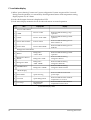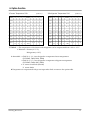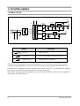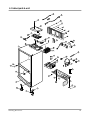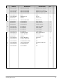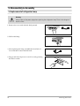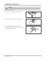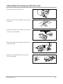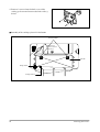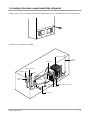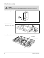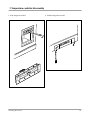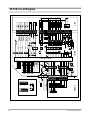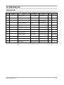
1
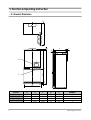
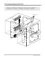
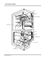
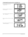
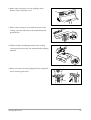
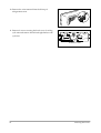
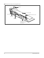
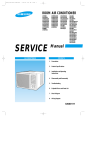
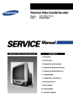
REFRIGERATOR
Model : SR-L676EV
SR-L678EV
SR-L626EV
SR-L628EV
GREEN
REFRIGERATOR
CONTENTS
1. Precautions
2. Product Specifications
3. Electrical Part Specifications & Standard
4. Circuit Diagram
5. Functions & Operating Instruction
6. Circuit Descriptions
7. Troubleshooting
8. Parts List
9. Disassembly & Assembly
10. PCB Circuit Diagram
SR-L676EV
SR-L678EV
SR-L626EV
SR-L628EV
11. PCB Parts List
12. Specifications of Main Components
2. Product Specifications
Model
SR-L628EV
Type
SR-L678EV
SR-L626EV
SR-676EV
(LMF(Freezer/Refrigerator) 2 Door)
Freezer performance
(4-STAR)
Temperature control
Electronic control
Yes
Water dispenser
Net Capacity
3
No
Freezer
171(6.04)
192(6.78)
171(6.04)
192(6.78)
Refrigerator
345(12.18)
376(13.28)
351(12.39)
382(13.49)
Total
516(18.22)
568(20.06)
522(18.43)
574(20.27)
l/(ft )
(WXDXH)
820X715X1790 (mm) (SR-L626(8)EV)
820X765X1790 (mm) (SR-L676(8)EV)
Refrigerant
HFC-134a(160gr)
Net dimension
Cabinet insulation
CYCLO-PENTANE
Door insulation
CYCLO-PENTANE
Cabinet
A.B.S
Door
A.B.S
Foam
Liner
Net weight
114Kg
113Kg
3. Electrical part specifications & standard
STANDARD
ITEM
Model
SR-L626/628EV
Input Source
220V
Refrigeration Cycle
Model
2
Compressor
Starting type
Evaporator
240V
SR-L626(8/676(8)EV
115V
SR-L676/678EV
127V
220V
240V
SK182H-L2U SK182Q-L2U SK182E-L2W SK182P-L2W SK190H-L2U SK190Q-L2U
RSCR
CSR
Oil charge
Freon α-15(ESTER)
Freezer
Split Fin Type
Refrigerator
Split Fin Type
RSCR
Condenser
Forced & Natural Convection Type
Dryer
Molecular Sieve XH-9
Capillary tube
ID0.85XL2500 3.79kg/cm2
Earth screw
BSBN(Brass screw)
Door switch
250V/0.5A
Samsung Electronics
ITEM
STANDARD
Freezer
Refrigerator
Temperature
Type
ON(˚C)
OFF(˚C)
High
–20˚C
–22˚C
Mid
–16.5˚C
–18.5˚C
Low
–14˚C
–16˚C
Mode
ON(˚C)
OFF(˚C)
High
–0.5˚C
–1.5˚C
Mid
3.5˚C
2.5˚C
Low
6.5˚C
5.5˚C
F-Sensor
Type
R-Sensor
Defrost cycle
Freezer:6 – 16hr/Refrigerator:12 – 32hr
Rest time
10min±2min
First cycle
4hr±10min
Defrosting
502AT
Refrigerator-Sensor
502AT
FRE EVAP-Sensor
502AT
REF EVAP-Sensor
502AT
Room TEMP-Sensor
502AT
FRE Defrost-Heater
200W (115V, 127V, 220V, 240V)
REF Defrost-Heater
130W (115V, 127V, 220V, 240V)
Heater
Sensor
Freezer-Sensor
Lamp-Heater
Fuse
Electrical parts
Mode
2W (115V, 127V, 220V, 240V)
250V 10A 72 ± 4˚C
FRE Defrost-Fuse
REF Defrost-Fuse
VOLTAGE
CONDENSER
OVER-LOAD
PROTECTOR
STARTINGRELAY
MOTOR-FAN
250V 10A 72 ± 4˚C
115V
127V
220V(626/628EV) 220V(676/678EV)
240V
STARTING
125VAC/125µF 125VAC/125µF
RUNNING
250VAC/12µF
250VAC/12µF
350VAC/5µF
350VAC/5µF
350VAC/5µF
MODEL
4TM445SHBYY-53
4TM444NHBYY-53
4TM308PHBYY-53
4TM314RHBYY-53
4TM232SHBYY-53
130˚C
135˚C
690˚C
ON TEMP.
OFF TEMP.
135˚C
MODEL
PTHAS-T100M200B
120˚C
125˚C
PTHAS-T100M200B PTHAS-T220M350D PTHAS-T220M350D PTHAS-T330M385D
RESISTANCE
10W ± 20%
22W ± 20%
33W ± 20%
FRE. REF.
IS3208TMDA-4 IS3208TMDA-8
IS3208TMDA-2A
IS3208TMDA-6
CIRCUIT-MOTOR
IS3208-SCF6A IS3208-SCO6A
IS3208-SCF7A
IS3208-SCL5A
FRE.
110V~130V/15W
220V/15W
240V/15W
LAMP
MOTOR-GEARED
Samsung Electronics
OSRAM DEULX S/E IIW
REF.
REF.
M2BC18AR02
M2LC18AR02
3
5. Function & Operating Instr uction
C
10
• 5-1 Product Dimension
D
40
77
11
10
E
B
"X"
A
673.5
8
"Y"
10
64
820
6
MODEL
A
B
C
D
E
Remarks
SRG-L678EV
SRG-L676EV
SR-L628EV
SR-L626EV
1750.0
1750.0
1750.0
1750.0
994.5
994.5
994.5
994.5
1509.7
1509.7
1459.7
1459.7
755
755
715
715
667
667
627
627
"X"
"Y"
"X"
"Y"
Samsung Electronics
5-2 Part Name & Disassembly
• Chilled Compartment
disassembly
• Top tray disassembly
Take out food stuffs and
pull it out by following
the arrow.
Pull it forward.
1. Pull it out by following
the arrow.
2. Bend the cover and
take it out.
①
•
•
•
②
Take out the water
bottle with the bottom
latch pressed.
•
•
•
• Tray disassembly
Pull it out by following
the arrow.
•
•
• Ice compartment
Samsung Electronics
• Vegetable compartment
• Freezing compartment
7
5-3 Circulation of Refrigerant (H.M CYCLE)
Compressor → Sub condenser → Cluster pipe → Hot pipe → Dryer → Capillary tube
→ R-Evaporator → F-Evaporator → Accumulator → Suction pipe → Compressor
SIDE CLUSTER PIPE
R
TO
RA
O
AP
EV
R-
CAPILLARY
TUBE
ACCUMULATOR
F-EVAPORATOR
SUCTION PIPE
SUB CONDENSER
8
DRYER
HOT PIPE
COMP.
Samsung Electronics
5-4 Cool Air Circulation
R-FAN
MOTOR
R-EVAPORATOR
SUCTION AIR
F-FAN
MOTOR
F-EVAPORATOR
OUTPUT AIR
SUCTION AIR
Samsung Electronics
9
QUICK HIGH …. FREEZER …. LOW
LOW ….REFRIGERATOR…. HIGH QUICK
X-FLOW
HIGH
HUMI
ALM
QUICK
FREEZER
ALARM
REFRIGERATOR
QUICK
SR-L628/678EV
QUICK HIGH …. FREEZER …. LOW
LOW ….REFRIGERATOR…. HIGH QUICK
X-FLOW
HIGH
HUMI
ALM
QUICK
FREEZER
TEMP.CONTROL
REFRIGERATOR
QUICK
SR-L626/676EV
1. Temperature Control Functions
A. Temperature control in the freezing compartment
1) Select the 5 STEPS of ‘MED’–‘MED · HIGH’–‘ HIGH’–‘LOW’–‘LOW · MED’ with one button.
2) When-ever the temperature control button of freezer is pressed, it continues to light from “MED”
to “LOW · MED”.
3) When power turns on “MED” is automatically selected.
Category
Initial power on
Pressed once Pressed twice Pressed 3 times Pressed 4 times
Indicator Lamp
MED
MED·HIGH
HIGH
LOW
LOW·MED
Reference Temp.
–17.5˚C
–19.5˚C
–21˚C
–15˚C
–16.5˚C
10
Remark
Samsung Electronics
B. Temperature control in the refrigeration compartment
1) Select the 5 stages of ‘MED’–‘MED · HIGH’–‘HIGH’–‘LOW’–‘LOW · MED’ with a button.
2) Whenever the temperature control button of refrigerator is pressed, it continues of light from
‘MED’ to ‘LOW · MED’.
3) When power turns on “MED” is automatically selected.
Category
Initial power on
Pressed once
Pressed twice Pressed 3 times Pressed 4 times
Indicator Lamp
MED
MED·HIGH
HIGH
LOW
LOW·MED
Reference Temp.
3˚C
1˚C
–1˚C
6˚C
4.5˚C
Remark
C. Power freezing and power refrigeration function
• It is selected by the special power freezing · refrigeration button.
• Whenever the power freezing · refrigeration button is pressed, it repeats turning on and off.
• When power turns on at first, it is selected to off automatically.
• When the power freezing · refrigeration button is selected, the temperatures of freezer and
refrigerator do not change. But, the temperatures can be set again after it is selected.
1) Power Freezing Function
① If power freezing is selected, COMP and F-FAN operate for 2 and 30 hours.(In 1 minute after
selection)
② If power freezing function finishes, power freezing lamp turns off.
③ If power freezing function is selected, refrigerator is controlled by the fixed notch.
2) Power Refrigeration Function
① If it is selected, it continues until COMP and R-FAN reaches to –4˚C.
② The power refrigeration finishes if COMP and R-FAN does not reach –4˚C even though 2 and
30 hour operation.
③ If it is selected, refrigerator is controlled by the fixed notch.
3) When the power freezing · refrigeration are selected simultaneously
① Each function is carried out at the same time.
Samsung Electronics
11
2. Alarm function
A. Button touch(Ding-Dong Sound)
1) When each button on the control panel is pressed, the beep sounds to confirul the key input.
2) The beep does not sound if wrong-touch.
B. Door open(Ding-Dong Sound)
1) When the door of either freezer of refrigerator is open for more than 2 minutes, the alarm rings.
2) The alarm rings for 10 seconds every one minute. When the door closes, the alarm goes off
immediately.
3) Door open alarm rings when the display button is selected. But door open alarm stops
immediately if the button is released.
4) If the alarm is selected by the button, the alarm rings regularly.
5) Alarm by the alarm button includes only door open.
6) Model SR-L676EV, SR-L626EV follows the above alarm procedure without alarm select button.
C. Forced starting · Forced defrosting (beep sound)
1) If the forced starting · forced defrosting are selected the beep tone sounds.
2) When forced starting, the beep sounds until being completed(24 hours) or released.
3) When forced defrosting, the beep sounds until being completed(including pause) or released.
3. Defrosting function
A. Quick defrosting function
1) When power turns on at first, the first defrosting is carried out after compressor operates for 4
hours.
B. Standard defrosting function
1) Defrosting is divided into freezer defrosting, refrigerator defrosting and natural defrosting. The
defrosting of freezer and refrigerator is determined by the operation time of compressor.
2) Defrosting interval can vary from 6~32 hours.
C. Natural defrosting of Refrigerator
1) Natural defrosting is carried out if the compressor turns off and fan keeps on for some period.
12
Samsung Electronics
4. Test function
A. Forced starting function
1) The test functions are designed for PCB, product test, process inspection and service activities.
2) The test switch is on the main PCB and when pressed once, it immediately works cooling without
comp delay.
3) If the forced starting is selected, freezer and refrigerator notches are selected to “HIGH” and
“HIGH”· MED”. Comp and F-Fan are controlled by pull-down and R-Fan is controlled by “HIGH
· MED” notch.
4) The pull-down function of forced starting maintains for 24 hours and it returns to normal
operation after defrosting(F, R) is automatically carried out.
5) During forced starting, all button inputs are available. Forced starting can be released when
power turns on after off or by the test release mode.
6) During forced starting, the beep continues to sound (0.25 sec. ON/0.75 sec OFF) until defrosting
is completed.
B. Forced defrosting function
1) If the test button is pressed once during the forced starting, refrigerator is defrosted forcedly.
2) If it is pressed twice, freezer and refrigerator carry out defrosting at the same time.
3) When the forced defrosting is carried out, the forced starting is released and returns to normal
operation.
4) When the forced defrosting is carried out, the notches of freezer and refrigerator maintains the
notch fixed prior to forced starting.
C. Test mode release
1) If the test button is pressed twice during forced defrosting, the forced defrosting is canceled and
returns to normal operation.
2) If the test release mode is selected, the buzzer will stop.
Samsung Electronics
13
5. Self-diagnosis function
A. Self-diagnosis function with initial power on
1) If the power is supplied to refrigerator at first, all displays are on and self-diagnosis function is
carried out.
2) If there is no defect on MICOM, display returns to the initial normal mode(“Med”–“HIGH
humidity”–“Alarm”).
3) If there is defect, the televant display lights off with the sound of the beep.
4) Self-diagnosis error indicator might disappear when defect is repaired or self-diagnosis function
is released.
5) If defect is repaired, display returns to normal mode.
6) Self-diagnosis function is canceled when “power freezing” button and “power refrigeration”
button are pressed for 5 seconds at the same time. Display returns to normal mode.
B. Self-diagnosis function during normal operation
1) Press “power freezing” button and “power refrigeration” button for 5 seconds at the same time
during normal operation.
2) The temperature LEDs of freezer and refrigerator repeats 1 second on/off 3 times.
3) If any button is not pressed until the temperature LED repeats on/off 3 times, self-diagnosis
function is carried out. If there is no defect, it returns to normal mode.
4) If there is defect, the corresponding display will light up and buzzer will beep.
5) Self-diagnosis error indicator works for 30 seconds and returns to normal mode regardless of
defect correction.
6) Key input is not available during self-diagnosis function.
7) When there is defect, the corresponding display is shown as initial power on.
14
Samsung Electronics
No
Item
Display LED
Symptom
Remark
1
R1-Sensor
Refrigerator “LOW”
• R-room left sensor housing
disconnection.
• Faulty connection.
• Wire open or short.
• Faulty sensor.
R1-Sensor temperature is
over +50˚C or below –50˚C.
2
R2-Sensor
Refrigerator
“LOW · Med”
• R-room left right sensor
housing disconnection.
• Faulty connection.
• Wire open or short.
• Faulty sensor.
R2-Sensor temperature is
over +50˚C or below –50˚C.
3
RD-Sensor
Refrigerator “Med”
• R-room defrost sensor
housing disconnection.
• Faulty connection.
• Wire open or short.
• Faulty sensor.
RD-Sensor temperature is
over +50˚C or below –50˚C.
4
Air-Sensor
Freezer “LOW”
• Outer sensor housing
disconnection.
• Faulty connection.
• Wire open or short.
• Faulty sensor.
Outer-Sensor temperature
is over +50˚C or below
–50˚C.
5
F-Sensor
Freezer “LOW” · Med”
• F-room sensor housing
disconnection.
• Faulty connection
• Wire open or short.
• Faulty sensor.
F-Sensor temperature is
over +50˚C or below –50˚C.
6
FD-Sensor
Freezer “Med”
• R-room defrost sensor
housing disconnection.
• Faulty connection.
• Wire open or short.
• Faulty sensor.
F-Sensor temperature is
over +50˚C or below –50˚C.
7
GearedMotor
Refrigerator “HIGH”
• Faulty geared-motor
• Faulty reed-switch
housing disconnection.
• Faulty connection.
Square wave not detected
by reed-S/W.
(Self-diagnosis Display Table)
Samsung Electronics
15
C. Load status display
1) When “power freezing” button and “power refrigeration” button are pressed for 5 seconds
during normal operation, it is activated by the refrigeration button while temperature setting
display repeats on/off 3 times.
2) Load which output of micom is displayed on LED.
3) Load status display maintains for 60 seconds and returns to normal operation.
No
Display LED
Item
Display
Freezer Subordinate
1
COMP
Freezer “LOW”
Relevant LED ON during comp
operation
2
F-FAN
Freezer “LOW · Med”
Relevant LED ON during F-FAN
operation
3
Freezer defrost Heater
Freezer “Med”
Relevant LED ON during freezer
defrost heater on
4
Freezer bulb
Freezer “Med · HIGH”
Relevant LED ON during freezer
bulb ON
Refrigerator Subordinate
5
R-FAN
Refrigerator
“LOW · Med”
Relevant LED ON during F-FAN
operation
6
Refrigerator defrost
Heater
Refrigerator “Med”
Relevant LED ON during
refrigerator defrost
7
Refrigerator bulb
Refrigerator
“Med · HIGH”
Relevant LED ON during
refrigerator bulb ON
8
GEARED-Motor
Refrigerator “HIGH”
Relevant LED ON during
refrigerator brade rotation
Mode Display
9
Initial Mode
Quick Freezing
Relevant LED ON with initial
power input
10
Overload
Quick Refrigeration
Relevant LED ON when ambient
temperature is over 35˚C
11
Low temp.
High humidity
refrigeration
Relevant LED On when ambient
temperature is below 20˚C
(Load Status Display Table)
16
Samsung Electronics
6. Option function
(Unit ˚C)
1) Freezer Temperature Shift
SHIFT 14
13 12 11 SHIFT 14 13
Reference
0
0
0
0
+0.5
1
-0.5
0
0
0
1
+1.0
-1.0
0
0
1
0
-1.5
0
0
1
-2.0
0
1
-2.5
0
-3.0
-3.5
(Unit ˚C)
2) Refrigerator Temperature Shift
12 11
SHIFT 18
17 16 15 SHIFT 18 17
16 15
0
0
0
Reference
0
0
0
0
+0.5
1
0
0
0
1
0
0
1
-0.5
0
0
0
1
+1.0
1
0
0
1
+1.5
1
0
1
0
-1.0
0
0
1
0
+1.5
1
0
1
0
1
+2.0
1
0
1
1
-1.5
0
0
1
1
+2.0
1
0
1
1
0
0
+2.5
1
1
0
0
-2.0
0
1
0
0
+2.5
1
1
0
0
1
0
1
+3.0
1
1
0
1
-2.5
0
1
0
1
+3.0
1
1
0
1
0
1
1
0
+3.5
1
1
1
0
-3.0
0
1
1
0
+3.5
1
1
1
0
0
1
1
1
+4.0
1
1
1
1
-3.5
0
1
1
1
+4.0
1
1
1
1
1) Method : • The temperature of the freezer and refrigerator can be compensated from +4.0 to –3.5˚C.
• Reference : Freezer (–17.5˚C)
Refrigerator(+3.0˚C)
As above table • Shift No 1, 2, 3, 4 are designed to compensate freezer temperature
(PCB D601, D602, D603, D604)
As above table • Shift No 5, 6, 7, 8 are designed to compensate refrigerator temperature
(PCB D605, D606, d607, D608)
As above table • “0” means non-diode (IN4148)
“1” means diode
❋ Temperature is compensated with power input after diode connects to the option table.
Samsung Electronics
17
6. Circuit Descriptions
1. Power cir cuit
(DC12V)
+12
HEAT-STICK
HEAT-STICK
7812
7805
BD05-08
1N4004 X 4
CON1
1
104
(MC7805)
FUSE2
250V 0.5A
(MC7805AC)
IC02
+
C103
WHT
BLK RED
GRY
BLK
BLU
GRN
1
3
5
7
IC03
HEAT-STICK
+
C109
C107 104
V12
(DC12V)
BD01-04
1N4004 X 4
5
7812
(MC7812)
+
C
C106
1000uF
35V
7
+12
IC03
470uF
25V
3
L V T
Voltage
Vcc
(DC5V)
ICO1
+
C
470uF
25V
Circuit used
(DC 12V)
Relay Operation
Vcc (DC 5V)
Power around MICOM & Sensor Detector
V12 (DC 12V)
LED Display & S/W Detector
The input AC voltage of DC-trans secondary registers 15V at CON1 between ①~③. The rectified
voltage passed through BD05 ~ 08 becomes DC 12V through voltage regulator MC7812(IC02). The
power(DC12V) is supplied to the relay operation power block. Then, DC 5V is genetatel and supplied
to the power around micom and sensor detector through 7805(IC03).
The rectified voltage passed through BD01~04 passes through 7812(IC01). Then, DC12V is supplied to
LED display and switch detector.
18
Samsung Electronics
2. Oscillator
30
30P
Xin
x-tal
31
Xout
30P
Port
Oscillating Fr equency
Xin
4.00MHz
Xout
4.00MHz
It is designed for clock generation and time
calculation for synchronizing transmission and
reception on the logic elements inside the MICOM.
If the X-TAL specification changes, MICOM may
make an error. The standard components should be
used.
±0.5% Error
3. Reset Circuit
R201
1K
KA7533
C203
1µF/25V
R202
29
10K
C202
104
When power is supplied to MICOM, reset circuit
initializes RAM and other parts on MICOM to
initialize all programs. Reset voltage maintains
“low” for hundreds of µsec comparing to MICOM
Vcc voltage when power is input. It also maintains
“high”(5V) during normal operation. But, when Vcc
drops to 3.3V, reset port becomes “low”.
RESET
Port
Voltage
Xin
5V
Xout
5V
4. Door S/W Detector
Vcc
R401(4.7K)
F-DOOR S/W
R402
CON06
7
10K
C401
104
R403(4.7K)
R-DOOR S/W
R404
8
10K
Samsung Electronics
C402
104
19
DOOR
Door Conditions
Door S/W Contact
CLOSE
F
R
MICOM
PIN NO
Micom Input Voltage
OPEN
OPEN
CLOSE
CLOSE
OPEN
OPEN
“LOW”
#7
“HIGH”
“LOW”
#8
CLOSE
“HIGH”
1) If door is open, door S/W contact is closed. Then MICOM receives “low” signal and detects
door open.
2) If door is closed, door S/W contact is open. Then MICOM receives “high” signal and detects
door close.
5. “V” Motor Position Detector(Reed S/W)
CON 02
7
REED S/W
Vcc
R405
4.7K
R406
43
6
10K
5
C403
104
1) The position of “V” motor for controlling the G.A–fuzzy of the temperature in the
refrigeration room is detected by the reed switch.
2) When MICOM Pin 43 changes ‘high’ to ‘low’ by the operation of fan, MICOM detects the
position of “V” motor.
20
Samsung Electronics
6. Temperature Sensor
R2-ROOM
R1-ROOM
THERMISTOR
F-ROOM
THERMISTOR
R / DEF - SONSOR
THERMISTOR
F / DEF - SONSOR
CON2
4
3
2
1
4
3
2
1
CON3
1
2
3
4
5
6
1
2
3
4
5
6
Vcc
R301
Vcc
10K-F
R302
R303
10K
10K (F)
R304
10K
Vcc
60
104
P64
C301
59
C09
104
C302
104
C303
104
C304
104
C305
104
C306
P63
R305
Vcc
Vcc
10K (F)
R306
R307
10K
10K (F)
R308
R309
10K
10K (F)
R310
10K
Vcc
P66
61
P65
58
P62
R311
10K (F)
"A"
62
R312
10K
63
P67
( Air Sensor)
When Sensor is open
When sensor is cut off
MICOM input “HIGH”
MICOM input “LOW”
1) The sensor uses the characteristics of thermistor. If temperature goes higher, resistance goes
lower. On the contrary, if temperature goes lower, resistance goes higher.
2) MICOM input voltage is counted by sensor as follows.
RTH
(VCC : 5V, RTH : Sensor reisitance)
VF =
X Vcc
RTH + R24
3) For the resistance information on temperature and MICOM input voltage, please refer the
conversion table. (Page. 41)
Samsung Electronics
21
7. Key scan and display circuitry
CON7
(XH-11P)
IC04
P04
P03
P02
P01
P00
13
3
12
4
11
5
10
6
16
10
10
10
15
9
9
9
14
4
4
4
3
3
3
2
2
2
1
5
6
7
8
11
1
5
6
7
8
11
1
5
6
7
8
11
13
7
12
8
9 GND VCC 10
9
UDN2003(2803)
+12
C23
104
IC05
P75
P74
P73
P72
P71
P70
6
1
18
GRID 05
5
2
17
GRID 04
4
3
16
GRID 03
3
4
15
GRID 02
2
5
14
1
13
6
GRID 01
R04
R502 10
1.2K
9
R503
1K
C501
3K
R501 4. 7 K
3K
X1
X2
X3
Alarm
HIGH
HUMI
X4
X5
X6
X-Flow
Quick FRE
F Temp. R Temp. Quick Quick Quick REF
REF
FRE
C
C
C-N
C-N
N
N
N-W
N-W
1N4148
S/W01
1N4148
S/W02
1N4148
S/W03
1N4148
S/W04
1N4148
S/W05
W
W
KEY INPUT
1) Key scan and display operation
As shown in the following waveform, MICOM pins #2 ~ #6 output are high for 2msec per 10msec.
MICOM pin #2 → #3 → #4 → #5 → #6 output repeats. The signal is output through IC05(UDN
2981A). At that time, the peak to peak voltage of square signal registers around 11V. The grid #1 ~#5
waveforms are as follows.
2 m Sec
8 m Sec
V
11V
Grid #1
Grid #2
Grid #3
Grid #4
Grid #5
O
V
t
Refrigerator Display
O
V
t
Freezer Display
O
V
t
Letter Display
O
V
t
O
t
22
“V” Function Display
“V” Function Display
Samsung Electronics
2) Key Scan
The grid waveform of each output is supplied to each button line through switching diode
(IN4148). The grid #1 signal goes to the setting button of refrigerator. Then, refrigerator button
is pressed, around 4.5V goes to IC05(UAN2981A) pin 8 through key input line. MICOM detects
the refrigerator button pressed after MICOM pin1 receives the signal.
8. Load Operation
CON9
RED
+12
9
9
RY01
7
7
RY02
SWING MOTOR
5
5
RY03
R-C/FAN
3
3
RY04
R-Defrost heater
COMP COOL FAN
IC06
18
1
R03
10K
11
8
(R-DEF-HET) 14
P05
(COMP-COOL FAN) 16
P07
SWING MOTOR 18
P11
(R CIRCLE-FAN) 19
P12
(R-LAMP) 21
P14
(F-LAMP) 22
P15
(F CIRCLE-FAN) 23
P16
(COMP) 24
P17
17
P10
(F-DEF-HET) 15
P06
C24
104
R
C
12
I
7
N
13
E
6
T
W
15
4
1
1
RY05
F-LAMP
9
9
RY06
15
3
F-C/FAN
7
7
RY07
17
2
COMP.
5
3
5
3
RY08
18
1
R-LAMP
O
R
CON10
(DC12V) +12
C27
104
SPK1-4
SQ-1201
1
1
5
3
1
5
3
1
CON8
F-Defrost heater
K
Vcc GND 9
ULN2803
IC07
AC1
RY09
17
2
R02
10K
IC06
C25
104
V12
If MICOM outputs “high” signal to driver-IC(ULN 2803) according to each load operation
conditions, IC turns on and DC 12V flows to ground through the relevant relay coil. Then, core is
magnetized by the coil current, and relay contact switches on. When relay contact is on, AC POWER
is supplied to the relevant operation load, then which will be activated. If MICOM outputs “low”
signal, load operation stops with the relevant relay contact off.
Samsung Electronics
23
1) Compressor and Defrost Heater
RY08
C
NC
AC POWER
RY09
C
NO
NC
RY01
NO
COMP
F-Defrost heater
R-Defrost heater
As above block diagram, the commons of compressor relay(RY 08) and defrost heater relay(RY 09,
RY 01) are respectively connected to AC POWER line. If relay is not activated(OFF) contact
maintaills NC, and compressor and defrost heater are all off, activated and contact is switched on.
Then, AC POWER is supplied to compressor activated. On the contrary, if defrost heater relay
operates, defrost heater is activated. Compressor and defrost heater do not operate simultaneously
under any conditions of relay.
RELAY
24
Load
Remark
off
Comp Operation
Defrost-Heater Power Off
on
on
Comp off, Defrost-Heater Off
off
on
Defrost-Heater On
off
off
Comp Off, Defrost-Heater Off
COMP
Defrost H
on
Comp Power Off
Samsung Electronics
9. Other option functions
Temperature and function values are changeable by using
main PCB switching diode.
• Note : If possible, do not change be cause the values have
been set in factory. When changing option functions,
power should be turned off.
(Only initial power-on allows reading option
function)
Vcc
P50
P51
P52
P53
P54
P30
P31
P32
P33
P34
P35
P36
P37
49
50
R12-16 1K X 5
51
52
53
51
41
31
21
11
52
42
32
22
12
53
43
33
23
13
54
44
34
24
14
55
45
35
25
15
56
46
36
26
16
57
47
37
27
17
58
48
38
28
18
33
34
35
36
37
38
39
40
R33 - 40
47K X 8
10. PCB Sub Ass’y(Inverter PCB)
TH-SW
C4
D8
RT2
D10
C6
R9
R8
R3
C5
Q1
R1
F1
R2
PT2
R5
RT1
LF1
D5
D1
D9
PT-1
CH2
CH1
D2
Q4
C1
DAC
D3 D4
R4
Q2
+
C3
D11
Q3
C8
C2
R10
R7
PT3
R6
ZD1
Samsung Electronics
25
1) Power circuit
PCB sub ass’y (Inverter PCB) is activated with AC POWER input when the refrigerator door is open
and R-lamp relay(RY05) is activated. If the AC POWER is supplied to the power block, the smooth
capacitor(C3) gets around VOLTAGE DC(VOLTAGE AC X 2) AC POWER through rectification.
2) Lamp
If power is supplied to the PCB sub ass’y, diac(DB4) is activated. When C4 is over 35C/DC, voltage
is supplied to TR Q2 base by the continuity of diac. Then, TR Q2 is activated.
When TR Q2 is activated, current flows to C5 – C6 – CH1 – PT1 – R9. At that time, current flows to
PT2 and PT3.
If the discharge of capacitor C6 is completed, reverse current flows to PT2 and PT3 and TR Q2 turns
off TR Q3 turns on. The current flows to PT1 – CH1 – C6 – C5 – C8.
Lamp light up by the repetition of TR Q2, Q3 on/off. Its frequency range is 30~40KHz during
on/off.
3) PTC and PTC protector
PTC is designed to smooth the lighting and to lengthen lamp’s life by heating filament of lamp. The
PTC protector prevents damage from PTC by cutting off power through triac if filament emits high
voltage at the beginning of lighting.
To check the PTC, measure resistance (150Ω ± 25% is normal). But, PTC resistance can be challged by
the ambient temperature and PTC operation. The above resistance value is counted in 20 sec after
lamp is off with the temperature 25˚C.
26
Samsung Electronics
4) Troubleshooting
Precautions
1. Is the power cord well connected to wall outlet?
2. Be careful of high-voltage discharge because high voltage DC power is supplied to SUB-PCB.
① When the light dosen ’t come on in the refrigerator
Start
Is power supplied to
sub-PCB?
N
Check wires and
main PCB relay
Y
N
N
Is power supplied to
smoother C2?
Y
Is TH-S/W normal?
Y
Check the power
Does lamp oscillate
at 35±5KHz?
N
Check PTC.
Replace lamp
Y
Repair C6, C7 or
PTC(RT1)
Replace TH-S/W
✻ PTC should be inspected before replacing lamp.
✻ Be careful of high voltage discharge, when repairing unit.
Samsung Electronics
27
7. Troubleshooting
Precautions
1. Is the power cord well connected to wall outlet?
2. Refer to the reference
1) No power
Start
DC-Trans primary
power input?
N
Check wires
Y
DC-Trans secondary
power input?
N
Replace DC-Trans
Y
Main PCB fuse
brown out?
N
Replace fuse
N
Power input to IC02?
Measure C03
(1000M/35V)
N
Check IC02(MC7812)
Y
DC 5V output
from IC03?
Measure IC03
OUT voltage
Check BD05 – 08
Y
DC 12V output
from IC02?
Measure IC02
OUT voltage
N
N
Check IC03(KA7805)
N
Are wires connected to
panel securely?
N
Check wire connection
Y
Panel PCB Ass’y
is OK?
Y
Reference 1
(Page. 38)
Y
Replace panel PCB
OK
28
Samsung Electronics
2) Compressor does not run
Precautions
1. Compressor does not operate in 5 minutes after power ON and compressor OFF.
2. Compressor does not run during defrosting.
3. Compressor does not run because low temperature is detected if freezer sensor is not connected.
Start
5 minutes after
compressor off?
N
Y
Is compressor
operated by forse?
Reference 6
Check it after 5 minutes
Y
(Page. 40)
N
N
Replace MICOM
and PCB
N
Replace IC07
N
Replace relay
Reference 7
(Page. 41)
MICOM pin24
output is “HIGH”?
Freezer sensor is
OK?
Y
Main PCB temperature
detector is OK?
Y
IC07 pin10 output
is “LOW”?
Y
Check wiring
N
Replace sensor
N
Check detector &
replace PCB
Y
Comp relay is OK?
Reference 2
(Page. 38)
Y
Connector CON 8, 10
contects are OK?
N
Check connector
Y
Comp ass’y is OK?
Y
N
Replace comp
Check wires connection
Samsung Electronics
29
3) No defrosting
Precautions
1. Even though both F·R-defrost sensors short-circuit, normal operation continues without
defrosting.(Refer to self-diagnosis function)
2. Even though the temperature fuse is off, there is no heating but defrosting natural
temperature increase comp off-time takes longer.
3. Even though both F·R-defrost sensor are open, heating does not end and comp-off
maintains with temperature fuse short-circuited.(Refer to self-diagnosis function)
Start
Does defrosting
start if the forced defrost
key is pressed?
N
N
Y
Y
Is power supplied to
defrost heater?
A
R Defrost H
F Defrost H
R Defrost H
F Defrost H
Y
Forced starting
N
#14
#15
#18
#19
Are MICOM pin 14, 15
“HIGH”?
RY01
RY09
N
Replace MICOM & PCB
Y
Are IC 06 pin 17, 18
“LOW”?
N
Replace IC06
Y
Defrost heater
relay is OK?
R Defrost H
F Defrost H
Reference7
(Page. 41)
Measure resistance
of defrost sensor
Does the defrost-sensor
register –5˚C?
Reference 2
(Page. 38)
N
Replace relay
Y
Connector CON C8, 09, 10
are OK?
N
Replace CON
Y
Evaparator temp. fuse
short-circuited?
N
Replace temperature fuse
Y
Defrost P-cord shortcircuited?
N
Replace EVAP ass’y
Check wire connection
30
Samsung Electronics
A
Return to normal?
Y
Normal
N
Defrost sensor
temperature is over than the finish
temperature?
Reference 7 (Page. 41)
Measure defrost-sensor
resistance
Y
Reference 7 (Page. 41)
Measure defrost-sensor
resistance
Y
Micom pins 58, 61
voltage is over than the finish
temperature?
Samsung Electronics
N
Replace the relative sensor
N
Replace temp. detector & PCB
Replace MICOM & PCB
31
5) Fan-motor does not run
Precautions
1. Compressor operates but fan does not run(F·R doors open)
2. Check door close
Start
Does compressor run?
N
Forced operation
Y
Is alarm lit up?
Reference 6
N
Press the alarm key
Y
N
N
Replace Micom&PCB
N
Replace ICO7
N
Replace RY04, O7
N
Connect connectors
N
Replace Fan motor
Are Micom pins 13, 17
low?
Y
Are IC07 pins 13, 17
low?
Y
RY04, 07 are OK?
Does alarm ring when
door is open?
Y
Are Micom pins 7, 8
low?
N
Y
Replace Micom, PCB
N
Are door S/W defector
OK?
Repair door S/W
detector & replace
Y
PCB
Y
Check wiring
CON 9, 10 connections
are OK?
Y
Fan motor are OK?
Y
Check wire connection
32
Samsung Electronics
5) Fan motor in the refrigeration room does not work
Precautions
1. Fan-motor operates with 2 modes.(Static or Rotation)
2. Fan-motor rotates for 30 seconds after one second of door open.
Start
Door open
Rotates after 1sec
of door open
N
N
Replace Micom & PCB
N
Does it stop if door
continues to open?
Y
Normal
Y
N
Replace IC07
Is Micom pin 12
“LOW”?
Y
N
Repair RY03
RY03 is OK?
Y
N
Connect connectors
CON09 connection
is OK?
Y
N
Check L/W
Motor L/W is OK?
Y
N
Replace Motor
Is Micom pin 18
“HIGH”?
Y
Motor is OK?
Y
Check parts location
Samsung Electronics
33
6) Lamp Inspection
Note
1. When replacing Sub-PCB, power should be turned off, because Sub-PCB receives AC POWER
INPUT and converts that to 1.5 X AC POWER INPUT.
2. It is impossible to check lamp with normal voltage tester, because lamp voltage is high.
References
1. If new lamp does not turn on, that’s because the protector is activated to prevent peak
voltage when lamp is replaced.
After replacing lamp, wait for 30 seconds after closing the door of refrigerator.
2. Lamp turns off automatically if the door of refrigerator is open for 10sec
If door is closed and opened by the door S/W, lamp turns on again.
If that carries out over twice, protector is activated and lamp maintains off.
3. If there is water in door S/W, lamp close not turn or off because Micom can not receive door
open/close signal. Door S/W should be checked.
4. The connection between Main-PCB and Sub-PCB, Sub-PCB output and cabinet L/W,
cabinet L/W and lamp are done by connector. If there is table with lamp check connector
and lamp.
5. Freezer lamp is controlled by main PCB.
34
Samsung Electronics
① Lamp in the refrigeration room does not light up
Start
Is lamp connected
to connector(pin4)?
N
Connect connector,
Faulty connection
Y
Is the
filament coil of lamp short
or faulty?
Faulty lamp, Replace it
Y
Is there
water in door S/W or connector
well connected?
N
Repair, Replace door S/W
Y
Is main
PCB connected to Sub-PCB
connector?
N
Connect connector,
Faulty Connection
Y
Sub-PCB fuse is OK?
N
Replace Sub-PCB fuse
Y
Check connector and door S/W.
Replace Sub-PCB
② Lamp in the freezer does not light up
Start
Is lamp connected
to connector?
N
Connect connector,
Faulty connection
Lamp filament
is OK?
N
Replace lamp(Filament short)
Y
Is there rated votage
on lamp connector?
Y
Replace lamp
N
Is there water in
door S/W or connector well
connected?
N
Repair, Replace door S/W
Check connector, door S/W and
lamp Normal
Samsung Electronics
35
8. Part List
1. Freezer
10
10-1
10-7
1
1-4
10-2
10-5
10-4
10-6
1-2
1-1
10-3
1-3
5
6
9-3
9
9-2
9-1
2
3
2-2
11-4
2-1
11-1
11-7
4
11-2
11-9
11-3
11-8
11-5
11-6
11
8
7
40
Samsung Electronics
NO
CODE-NO
1
DA67-40203D
ASS'Y-TRAY ICE
HIPS
1
1-1
DA71-20120A
FIXER-TRAY ICE
HIPS
1
1-2
DA67-40182A
TRAY-ICE
PP
2
1-3
DA64-40111A
KNOB-TRAY, ICE
HIPS
2
1-4
DA61-20102A
SPRING
STS 304B WPB
2
2
DA67-40200C
ASS'Y-TRAY, FREE(UPP)
HIPS
1
2-1
DA66-10104A
ROLLER
POM
12
2-2
DA71-20145A
FIXER-ROLLER
NY-66
12
3
DA67-40201C
ASS'Y-TRAY, FREE(MID)
HIPS
1
4
DA67-40202C
ASS'Y-TRAY, FREE(LOW)
HIPS
1
5
DA67-10208A
TRAY-ICE CUBE
ABS
1
7
DA63-10012A
ASS'Y-COVER EVAP FR(F)
PP(BJ-730)
1
8
6002-000454
SCREW TAP, TH
TH 2S-4X12 STS
2
9
DA59-40112C
EVAPORATOR-FRE ASS'Y
220V
1
DA59-40112D
EVAPORATOR-FRE ASS'Y
240V
1
DA59-40215K
EVAPORATOR-FRE ASS'Y
127V
1
DA59-40112E
EVAPORATOR-FRE ASS'Y
110V
1
9-1
6501-000123
CABLE-TIE
L=140
2
9-2
DA32-10105G
SENSOR DEF(R)
502AT
1
9-3
DA47-10148A
ASS'Y-FUSE THERMOS
250V/10A
1
10
DA61-70181G
ASS'Y-SUPT FRE
10-1
DA61-70114A
SUPT FREE L
HIPS
1
10-2
DA61-70115A
SUPT FREE R
HIPS
1
10-3
DA63-10400B
COVER-LAMP F
MIPS
1
10-4
DA47-40112P
SOCKET-LAMP
24PBT
1
10-5
DA32-10105A
SENSOR FRE
502AT
1
10-6
4713-000188
LAMP-FRE
220V/15W
1
4713-000213
LAMP-FRE
240V/15W
1
4713-000178
LAMP-FRE
110V~130V/15W
1
10-7
DA63-40105A
GROMMET-RAIL
RUBBER
2
11
DA63-10013A
ASS'Y-COVER EVAP, RE(F)
220V/50,60HZ
1
DA63-10013C
ASS'Y-COVER EVAP, RE(F)
240V/50HZ
1
DA63-10013H
ASS'Y-COVER EVAP, RE(F)
127V/60HZ
1
DA63-10013F
ASS'Y-COVER EVAP, RE(F)
110V/60HZ
1
11-1
DA63-10214A
COVER-EVAP RE(F)
PP
1
11-2
DA63-10364A
COVER-MOTOR FAN
PP
1
11-3
DA31-20103A
MOTOR-FAN
ABS Φ 90
1
Samsung Electronics
ITEM
SPECIFICATION
Q’TY
REMARK
1
41
NO
11-4
11-5
CODE-NO
ITEM
SPECIFICATION
Q’TY
DA31-10109B
MOTOR FAN
AMRHB-008WTEB
1
DA31-10109F
MOTOR FAN
AMRHB-008UVEB
1
DA31-10109W
MOTOR FAN
AMRHB-008ZREB
1
DA31-10109D
MOTOR FAN
AMRHB-008ZQEB
1
DA61-20128D
SPRING-FAN
STS 27WR
1
SEAL-COVER EVAP RE(F)
FOAM-LEX ALT3
1
11-6
11-7
6002-000224
SCREW TAP TH
2S-4 X 12 FE FZY
1
11-8
DA72-60042A
GROMMET-CASE MOTOR
NBR(BLK)
1
DA63-40119A
GROMMET-FAN MOTOR
NBR(BLK)
1
11-9
42
REMARK
Samsung Electronics
2. Refrigeration room
25-3
25-2
25
25-1
15
26
23
11
18
17
13
9-8
9-2
9-9
9-3
9
9-1
9-5
9-7
14
9-9
9-11
9-4
16
20
9-6
28
24
9-12
9-10
10
16-1
27
19
4
4-1
21
8
3
5
3-1
5-1
5-2
7
6
22
2-2
12-7
2
1
2-1
12-6
1-2
12-2
12
12-4
12-3
12-5
1-4
12-1
1-3
1-1
Samsung Electronics
43
NO
CODE-NO
DESCRIPTION
SPECIFICATION
Q’TY
1
DA67-10230B
ASS'Y-WARE VEGETABLE
ABS
1
1-1
DA67-10229A
WARE-VEGETABLE
ABS 711 X 409 X 221
1
1-2
DA63-10359B
COVER-VEGETABLE
GPPS 711 X 211 X 67
1
1-3
DA66-10104A
ROLLER-FREE
POM
4
1-4
DA71-20145A
FIXER-ROLLER
NY-66
4
2
DA67-20169B
ASS'Y-SHELF REF LOW
2-1
DA67-20142B
SHELF-REF LOW
ABS 721 X 404 X 24
1
2-2
DA64-20116A
TRIM-SHELF LOW
T=0.5
3
3
DA67-20170B
ASS'Y-SHELF REF MID(A)
3-1
DA67-20143B
SHELF-REF MID(A)
4
DA67-20171B
ASS'Y-SHELF REF MID(B)
4-1
DA67-20144B
SHELF-REF MID(B)
5
DA67-20190C
ASS'Y-SHELF REF UPP
5-1
DA67-20140A
SHELF-REF UPP
GPPS 338.5 X 250 X 24
1
5-2
DA64-20117A
TRIM-SHELF UPP
T=0.5 GOLD
1
6
DA63-30113A
GASKET-VEG FR
RD-PVC & SOFT-PVC
1
7
DA67-40194A
POCKET-VEGETABLE
GPPS 679 X 158 X 65
1
8
DA63-10577C
ASS'Y-COVER CHILLED
9
DA63-10534E
ASS'Y-COVER EVAP RE(R)
220V/50HZ
1
DA63-10534F
ASS'Y-COVER EVAP RE(R)
240V/50HZ
1
DA63-10534R
ASS'Y-COVER EVAP RE(R)
127V/60HZ
1
DA63-10534G
ASS'Y-COVER EVAP RE(R)
110V/60HZ
1
COVER-EVAP RE(R)
PP 669 X 239 X 105
1
9-1
1
1
ABS 723 X 400.5 X 24
1
1
ABS 723 X 331.5 X 24
1
1
1
9-2
DA63-10364A
COVER-MOTOR FAN
PP 75.5 X 95 X 47
1
9-3
DA31-20103A
FAN
ABS P190 X 27
1
9-4
DA31-10109B
MOTOR FAN
220V/50HZ
1
DA31-10109F
MOTOR FAN
240V/50HZ
1
DA31-10109W
MOTOR FAN
127V/60HZ
1
DA31-10109D
MOTOR FAN
110V/60HZ
1
9-5
DA61-20128D
SPRING-FAN
STS 27WR
1
9-6
DA72-60160A
SEAL-COVER EVAP RE(R)
FOAM-LEX(AL) B
1
9-7
DA72-60042A
GROMMET-CASE MOTOR
NBR(BLK)
1
9-8
6002-000224
SCREW-TAP TH
2S-FX12 FE FZY
1
9-9
DA63-40119A
GROMMET-FAN MOTOR
NBR
2
9-10
DA72-60171A
SPACER-COVER B
FOAM-PS
1
9-11
DA72-60170A
SEAL-COVER EVAP RE(L)
FOAM-LEX T=3
1
9-12
SPPS
SEAL-COVER EVAP RE(R)
1
DA67-10144A
CASE-EGG
1
10
44
REMARK
Samsung Electronics
NO
CODE-NO
DESCRIPTION
SPECIFICATION
Q’TY
11
DA63-10467A
COVER-SENSOR REF
HIPS
2
12
DA74-20130D
ASS'Y-COVER DUCT REF
220V~240V
1
DA74-20130F
ASS'Y-COVER DUCT REF
110V~127V
1
12-1
DA63-10215A
COVER-DUCT REF
12-2
DA31-20003A
BLADE-AIR
HIPS 477 X 232 X 54
1
12-3
DA72-40178A
SPACER-COVER DUCT
FOAM-PS
1
12-4
DA72-60159A
SEAL-DUCT RE
FOAM-PS
1
12-5
DA60-40104B
WASHER
HIPS Φ4 X T1.0
1
12-6
DA31-10107D
ASS'Y-GEARD MOTOR
M2 LC 18AR 02
1
1
DA31-10107E
ASS'Y-GEARD MOTOR
M2 BC 18AR 02
1
12-7
DA72-60161C
SEAL-DUCT, AIR
EDPM T=5
1
13
DA32-10105B
SENSOR-R
502AT
1
14
6002-000454
SCREW
TH T2-4 X 12 STS
2
15
DA02-90106B
CATALYST
T15 X W40 X L70
2
16
DA72-40010C
ASS'Y-SPACER COVER EVAP R
FOAM-PS
1
16-1
DA39-20122A
WIRE-GEARD MOTOR
17
DA63-10474A
COVER-LAMP R ASS'Y
ABS+PMMA
1
18
4713-000175
CFL-LAMP
11W OSRAM
1
19
6002-000454
SCREW
TH T2-4 X 12 STS
1
20
DA63-10220
COVER-EVAP REF FR
HIPS 671 X 275 X 115
2
21
DA61-70119A
SUPPORT-CHILLED
GPPS
1
22
DA67-40141A
TRAY-CHILLED
GPPS
1
23
DA72-60020A
SEAL-ABSORBER SOUND
T3 X 300 X 40 PAM
1
24
DA67-40169A
TRAY-EGG
GPPS
1
25
DA59-40111C
EVAPORATOR REF ASS'Y
220V
1
DA59-40111D
EVAPORATOR REF ASS'Y
240V
1
DA59-40238E
EVAPORATOR REF ASS'Y
127V
1
1
DA59-40111E
EVAPORATOR REF ASS'Y
110V
1
25-1
DA47-10148B
ASS'Y-THERMOS FUSE
250V/10A
1
25-2
DA32-10105G
SENSOR-DEF R
125, 250V, 10.5A
1
25-3
6501-000123
CABLE-TIE
NY-66 L=140
1
26
DA63-10461A
CAP-PURIFIER
ABS
1
27
DA67-30266D
CAP-SCREW
PP SC-93437R
2
28
DA63-10363A
COVER-EGG
GPPS
1
Samsung Electronics
REMARK
45
3. Door parts
23
25
21
34
22
40
1
6
5
36
8
37
10
19
38
4
1-1
33
18
7
39
13
14
3
15
16
9
1-4
17
1-2
1-3
11-5
27
11
24
11-4
11-1
11-12
20
11-6
26
11-2
11-8
11-3
11-9
11-14
2-1
2
11-10
SR-L676EV
SR-L626EV
11-13
1-4
11-11
31
1-3
29
11-7
11-15
12
41
11-16
32
1-2
27
28
30
46
Samsung Electronics
NO
CODE-NO
1
DESCRIPTION
ASS'Y-DOOR FOAM REF
SPECIFICATION
SR-L628EV/L678EV
Q’TY
1
1-1
DA63-30178A
GASKET-DOOR REF
1-2
DA71-40135A
STOPPER-MID
STS 304 T2
2
1-3
DA63-40118A
GROMMET-HINGE MID
POM
2
1-4
DA66-90111A
ASS'Y-AUTO CLOSE
POM
2
2
1
ASS'Y-DOOR FRE
1
2-1
DA63-30178B
GASKET-FREE
1
3
DA63-20001A
GUARD-REF LOW ASS'Y
1
4
DA63-20175A
GUARD-REF MID R
GPPS
1
5
DA63-20185A
GUARD-REF UPP L
GPPS
2
6
DA63-20150A
GUARD-REF UPP R
GPPS
2
7
DA71-70108A
GUIDE-BOTTLE
PE
2
8
DA64-50113B
ASS'Y-MASCOT
GOLD
1
9
DA71-20155A
FIXER-CASE ASS'Y
POMPOUNT M-203
1
10
DA63-20171A
GUARD-REF MID L
GPPS
1
11
DA74-90107A
ASS'Y-WATER DISPENSER
PC/BIO SENSOR
1
11-1
DA74-90001A
ASS'Y-COCK
LD-PE
1
11-2
DA67-30216A
CAP-COVER TANK
ABS
1
11-3
DA29-10001A
FILTER-WATER
PE
1
11-4
DA63-30003B
PACKING-BOTTLE B
SILICONE(TSE-221)
1
11-5
DA67-30208A
CAP-AIR DRAIN
ABS
1
11-6
DA60-90103A
O-RING A
SILICONE(TSE-221)
1
11-7
DA67-10163A
CASE-DISPENSER C
PC
1
11-8
DA71-70124A
GUIDE-PUSH
PC
1
11-9
DA60-90103B
O-RING B
SILICONE(TSE-221)
1
11-10
DA61-20102A
SPRING A
STS 304 WPB
1
11-11
DA71-70123A
GUIDE-PIN
PC
1
PACKING-BOTTLE C
SILICONE(TSE-221)
1
11-12
11-13
DA74-90118A
TANK-WATER
ABS
1
11-14
DA63-10401A
COVER-TANK
ABS
1
11-15
DA63-30139A
GASKET-COVER TANK
SILICONE(TSE-221)
1
11-16
DA65-20004A
CLAMP-TANK
ABS
2
SUPT-GASKET B
ABS
2
12
13
DA64-20121A
TRIM-DISPENSER ASS'Y
ABS(MP-960)
1
14
DA63-30002A
PACKING TRAY
SILICONE(TSE-221)
1
15
6002-000454
SCREW TH
TH 4 X 10 STS
8
Samsung Electronics
REMARK
A/S PART
47
NO
CODE-NO
DESCRIPTION
SPECIFICATION
Q’TY
16
DA63-10472C
COVER-DISPENSER ASS'Y
17
DA41-20101B
ASS'Y-PCB DISPLAY
18
DA67-40167B
TRAY-WATER
ABS
1
19
DA64-20104A
TRIM-TRAY
ABS(MP-0160)
1
20
DA61-10153A
ASS'Y-HINGE MID
21
DA61-10151A
HINGE-UPP
SHP1 T3.2
1
22
DA63-50138A
SHIM-HINGE UPP
RD-PVC T1
1
23
DA63-10399A
CAP-HINGE UPP
ABS
1
24
DA60-10123A
SCREW-TAP TITE
TAP TITE M6 X 24
1
25
DA60-10123B
SCREW-TAP TITE
TAP TITE M6 X 16
2
26
6002-000458
SCREW-TH
FH1 4 X 16 STS
4
27
DA71-10272A
REINF-HINGE, REF
SHP1 T3
1
33
DA63-20188A
GUARD-VARIETY, A
GPPS
2
34
DA63-10504B
CAP-AIR
ABS
1
36
LABEL-WORLD BEST
PVC
2
37
LABEL-NON CFC, A
WHT21
1
38
LABEL-USAGE, DISP
PVC
1
39
LABEL-LOCK
PVC
1
40
ASS'Y-DOOR, REF
A/S PART
1
ABS
REMARK
1
1
1
41
DA60-40104D
WASHER
ID11.2
1
42
DA60-40104E
WASHER
ID13.0
1
ASS'Y-DOOR FOAM REF
SR-L626EV/L676EV
1
SR-L676EV, SR-L626EV
1
1-1
DA63-30178A
GASKET-DOOE REF
28
DA41-20102C
PCB-PANEL ASS'Y
SR-L626EV/L676EV
1
29
DA63-10366A
COVER-PCB HANDLE
SR-L626EV/L676EV
1
30
DA61-60101C
SLIDER ASS'Y
SR-L626EV/L676EV
1
31
DA63-20152A
GUARD-REF MID
GPPS
1
32
DA63-20149A
GUARD REF LOW ASS'Y
GPPS
1
35
DA63-20189A
GUARD-VARIETY, B
GPPS
1
ASS'Y-DOOR REF
A/S PART
1
41
48
1
Samsung Electronics
4. Cabinet parts & unit
9
19
30
36
34
39
43
40
33
32
35
18
15
27
28
29
38
8
1
31
13
17
10
20
5
6
7
26
11
14
42
16
12
25
21
24
37
41
23
22
3
2
4
Samsung Electronics
49
NO
CODE-NO
1
2
3
4
5
6
7
8
9
10
11
12
13
14
15
16
17
18
19
20
21
22
23
24
25
26
50
DA61-40110A
DA61-10143A
DA61-30103A
SK190Q-L2U
SK190H-L2U
SK182Q-L2U
SK182H-L2U
SK182P-L2W
SK182E-L2W
DA34-10003W
DA34-10003N
DA34-10003G
DA34-10003P
DA34-10003E
DA35-10003L
DA35-10002N
DA35-10003H
DA63-10477A
DA32-10105F
DA65-20101A
DA63-40165A
DA34-10122A
DA73-30102A
DA60-10124A
6501-000123
DA74-30131A
DA63-40171B
DA41-20002A
DA41-20147A
DA41-20160A
DA41-20148A
DA60-10124A
DA71-60119A
DA60-90101A
DA61-40101A
DA66-20112A
DA60-10107A
DA67-40204A
ITEM
ASS'Y-CABI FOAM
ASS'Y-CABI FOAM
ASS'Y-MOVING CASTER
HINGE-LOW
LEG-FRONT
COMPRESSOR
COMPRESSOR
COMPRESSOR
COMPRESSOR
COMPRESSOR
COMPRESSOR
O/L-PROTECTOR
O/L-PROTECTOR
O/L-PROTECTOR
O/L-PROTECTOR
O/L-PROTECTOR
PTC-RELAY
PTC-RELAY
PTC-RELAY
COVER-RELAY
SENSOR-EXIT
CLAMP-COMP
GROMMET-COMP
SWITCH-DOOR
DRYER
SCREW-TAP TITE
CABLE-TIE
HOSE-DRAIN SUB
GROMMET-DIS. PIPE
ASS'Y-PCB INVERTER
ASS'Y-PCB INVERTER
ASS'Y-PCB INVERTER
ASS'Y-PCB INVERTER
POWER-CORD AC
SCREW-TAP TITE
BASE-COMP
RIVET-CASTER
CASTER-REAR
SHAFT-COMP
SCREW-EARTH
ASS'Y-TRAY DRAIN WATER
SPECIFICATION
Q’TY
SRG-L678EV
SRG-L676EV
SHPI T3.2
P.P
240V/50HZ SR-L676(8)EV
220V/50, 60HZ SR-L626(8)EV
240V/50HZ SR-L626(8)EV
220V/50, 60HZ SR-L626(8)EV
127V/60HZ SR-L626(8)/676(8)EV
110V/60HZ SR-L626(8)/676(8)EV
4TM314RHBYY-53
4TM308PHBYY-53
4TM232SHBYY-53
4TM444NHBYY-53
4TM445SHBYY-53
PTHAS-T220M350D
PTHAS-T330M385D
PTHAS-T100M200B
NORYL T2 BLK HOOK
STC5
NBR
250V
L140
M4
NY-66
HDPE
NBR
220V/50HZ
240V/50HZ
127V/60HZ
110V/60HZ
OPTION
M4 X 12
SBHG1
MSWR 18A
NY-66
SUM 24
BSBN PT M4 X 10
REMARK
1
1
2
1
1
1
1
1
1
1
1
1
1
1
1
1
1
1
1
1
4
4
1
1
1
1
1
2
4
1
1
1
1
1
2
1
2
2
4
1
1
Samsung Electronics
NO
27
CODE-NO
DESCRIPTION
SPECIFICATION
Q’TY
DA31-10110F
CIRCUIT-MOTOR
IS3208-SCF7A 220/50
1
DA31-10110H
CIRCUIT-MOTOR
IS3208-SCL5A 240/50
1
DA31-10110L
CIRCUIT-MOTOR
IS3208-SCO6A 127V/60HZ
1
DA31-10110G
CIRCUIT-MOTOR
IS3208-SCH6A 110/60
1
28
DA31-20101A
FAN
ABS
2
29
DA61-20128D
SPRING-FAN
STS 27
1
30
6002-000215
SCREW
TH1 4 X 16
1
31
DA73-10301A
ASS'Y-SUB COND
SR-L49, L52
1
32
2501-000401
CAPACITOR
5µF/350VAC
1
2401-000511
CAPACITOR
12µF/250VAC
1
2501-000275
CAPACITOR
125µF/125VAC
1
DA26-30110C
DC-TRANS
220V/50, 60HZ
1
DA26-30110A
DC-TRANS
240V/50HZ
1
DA26-30112B
DC-TRANS
127V/60HZ
1
DA26-30112A
DC-TRANS
110V/60HZ
1
34
DA63-10211A
COVER-COMP
SECC(POM) T0.45
1
35
DA72-60020A
SEAL-ABSORB
PAM T10
1
36
6002-000215
SCREW
1.4 X 12 FE FZY
1
37
DA72-60020A
SEAL-ABSORB R
PAM T10
1
38
DA67-10105A
CASE-PCB PANEL
P.P
1
39
DA63-10001B
COVER-PCB PANEL
P.P
1
40
DA41-20105B
ASS'Y-MAIN PCB
T1.6 X W136 X L197
1
41
DA63-10262A
COVER-LEG FR
P.P
1
42
DA67-30218G
CAP-SCREW
P.P
1
33
Samsung Electronics
REMARK
51
9. Disassembly & Assembly
1. Replacement of refrigerator lamp
Warning
Always take out the power plug when replacing the refrigerator lamp. There is the danger of
electric shock.
1. Remove the cover with the back latch pressed.
2. Pull out the lamp.
3. After replacing the lamp, assemble the front latch of
cover and then connect the back latch.
4. Plug in and check if power is cut off or not by pressing
the R-door switch.
52
Samsung Electronics
2. Replacement of freezer lamp
Warning
Always take out the power plug when replacing the refrigerator lamp. There is the danger of
electric shock.
1. Remove the cover by pressing the bottom latch.
2. Replace the lamp by turning it counter-clock wise.
3. Reassemble the cover in the reverse order of
disassembly and plug in and the check if power is cut
off by pressing the door switch.
Samsung Electronics
53
3. Disassembly of the cooling cycle in the r efrigeration room
1. Take out food stuffs and trays from
refrigeration room.
2. Bend the cover of chilled compartment and
remove the left axis.
3. Move the holder of chilled compartment to the
arrow ¨ and pull it out.
1
1
2
4. Remove 2 cap screws with (–) driver or similar
tools.
2 screws
5. Remove 2 latches from the bottom of the cover
in the front of evaporator.
54
Samsung Electronics
6. Remove the evaporator cover by pulling out the
bottom of the evaporator cover.
7. Remove the housing of wires from the center of the
cooling cycle unit and remove the terminal from the
geared motor.
8. Pull forward the insulating material of the cooling
cycle unit and remove the wire terminal and insulating
material.
9. Remove 2 screws securing refrigerator duct and pull it
out by following the arrow.
Remove 2 screws
Samsung Electronics
55
10. Remove the wire terminal from the left top of
refrigeration room
11. Remove 2 screws securing the back cover of cooling
cycle unit and remove the left and right latches with
(–) driver.
latch
Remove 2 screws
56
Samsung Electronics
■ Cooling cycle unit assembly in the refrigeration room
2 holders securing evaporator
Absorber
sound(Noise protector)
Temp. sensor
EVAP
TAPE-AL
(Groove for preventing
small ice when
defrosting)
■ Cooling cycle unit cover assembly in the refrigeration room
Noise protector
Frost spreading
protection
Samsung Electronics
57
■ Rotating duct assembly in the refrigeration room
Seal-air
Cover-duct, REF
Motor-Geared
Washer(Prevention noise)
Reed S/W
Blade-air
Seal-duct, RE
(Prevention Temp.
distribution)
58
Samsung Electronics
4. Disassembly of the cooling cycle unit in the fr eezer
1. Take out the case from the freezer.
2. Remove 2 screws from the holder of the cooling
cycle unit.
2 screws
3. Pull out the holder of the cooling cycle unit and
disconnect wire terminals.
①
②
4. Remove the latch of the cooling cycle unit cover
from the bottom.
②
③
①
5. Remove each terminal from the top of the
left wire assembly.
Samsung Electronics
59
6. Remove 2 screws from the back cover of the
cooling cycle unit and remove the latch with (–)
driver.
■ Assembly of the cooling cycle unit in the freezer
EVAP holder
Maintains 45˚
(Coolant & noise
reduction)
EVAP
Temp. Fuse
Temp. Sensor
60
Samsung Electronics
5. Assembly of mechanic compar tment in the refrigerator
1. Remove the screws securing the mechanic compartment cover of the back bottom of the refrigerator.
2. Mechanic compartment assembly
Sub-condenser
Cooling fan
Condenser
entrance
Hot-pipe entrance
Condenser outlet
S-Pipe
Hot-pipe
outlet
Noise & Vibration Sub-condenser entrance
reduction rubber
Compressor
Samsung Electronics
61
6. Electric box assembly
Warning
Make sure the power plug is taken out when replacing the components for the main PCB.
1. Disconnect the power cord.
2. Remove the cover of
electrical box with – driver.
3. Assembly specification of electric box
TEST S/W
Condenser
D/C Trans
62
Samsung Electronics
7. Temperature controller disassembly
1. With dispenser model.
Samsung Electronics
2. Without dispenser model
63
10. PCB Circuit Diagram
HALL IC
SET
CON1
7
1
3
5
1
3
5
9
7
9
7
LVT
R-
7
CON9
RED
SWING MOTOR
COMP COOL FAN
9
1
9
1
7
5
3
1
5
3
1
7
6
5
4
3
2
1
1
2
3
7
6
5
4
3
2
1
1
2
3
4
5
6
1
2
3
5
3
1
7
5
3
1
5
3
(R-C/FAN)
(F-C/FAN)
CON3
CON2
YEL
CON6
CON8
CON10
5
3
F-
F-DOOR S/W
R-DOOR S/W
Vcc
OUTPUT
G
R2-ROOM
R1-ROOM
THERMISTOR
F-ROOM
THERMISTOR
R / DEF - SONSOR
THERMISTOR
F / DEF - SONSOR
1
2
3
4
5
6
FUSE2
250V 0.5A
BDO5-08
1N4004 X4
BD01-04
1N4004 X 4
SPK1-4
SQ-1201
Vcc
Vcc
V12
(DC12V)
V12
(DC12V)
C11
223
Vcc
Vcc
Vcc
Vcc
C05
223
C06
223
+
HEAT-SLNK
+
HEAT-SINK C28
104
C04
470uF
25V
+
7805
(MC7805AC)
IC03
C02
2200uF
25V
7812
(MC7812C)
IC01
HEAT-SINK
7812
(MC7812C)
IC02
C03
C07
1000uF
35V
+
1000uF
35V
(DC12V) +12
+
C01
470uF
25V
Vcc
(DC5V)
(DC12V)
+12
V12
(DC12V)
IC06
RY01
1
7
8
12
6
18
RY03
13
RY05
15
3
1
2
17
K
IC06
13
12
2
10 Vcc GND 9
ULN2803
IC07
18
16
C27
Vcc
6
7
104
K
17
R47
6.8K
RY06
4
RY04
11
(DC12V) +12
RY02
C19
104
C18
104
R48
6.8K
Q02
KSC1008
R30
R31
10K
10K
R19
10K
R18
R49
1K
RY07
RY08
RY09
R21
10K
R22
10K
R28
R27
10K(F)
10K(F)
R24
10K
R25
10K(F)
R26
10K
R20
10K
10K(F)
R23
R17
Vcc
10K(F)
10K(F)
"A"
Vcc
Vcc
R03
10K
R02
10K
R08
R06
4.7K
4.7K
R46
1K
10K
R01
X-TAL
MAIN
C13
104
30P
30P
IC08
64
55
30
Vdd
VAREF
Xin
IC1
P13
P41
P04
P02
31 Xout
29
RESET
C26
104
28 P22(XTOUT)
P01
P17
P16
P15
21 P14
22
24
17 P10
P20
P60
P40
P43
TEST
VSS
VASS
P45-47
P22
P37
P36
P35
P34
P33
20
42
13
12
11
10
9
14
IC07
R45
4.7K
5
UDN2981A
V12
R44
12K
Q03
KSR1005
COIL
BUZZER
D09
1N4004
R42
Q01
4.7
KSR1005
42
41
34
33
32
31
25
24
23
22
21
17
16
15
14
13
12
11
R43
4.7K
V12
CON7
33UF
25V
C29
4
4
9
3
4
9
1
2
1
2
CON5
CON4
BLU
1
2
3
4
5
6
7
8
9
X1
X2
N-W
N-W
W
W
RC-NETWORK
N-8
1N4148
1N4148
1N4148
10
1N4148
1
2
3
4
5
6
7
8
9
S/W01
S/W02
S/W03
S/W04
S/W05
18
17
16
15
14
13
12
11
10
UDN2981A
SCHEMATIC DIAGRAM
9
1N4148
PANEL
X3
N
N
X6
C-N
X5
C-N
X4
C
*
*
C
EXT-ROOM
THERMISTOR
2
TEST JIG
1
18
17
16
15
14
13
12
11
10
ULN2803
SCHEMATIC DIAGRAM
KEY INPUT
S/W06
WIRE TO WIRE
1 1 1
5 5 5
6 6 6
7 7 7
8 8 8
11 11 11
2
2
3
9
51
43
35
26
18
3
10 10 10
52
44
36
28
27
2
16
UDN2981A
GRID #5
+12
15
13
3
12
4
C23
104
14
6
10
18
R04
5
GND VCC
ULN2803
IC06
UDN2981A
7
9
1
GRID #4
6
17
GRID #2
2
15
5
4
GRID #3
3
GRID #1
16
ZD1
"A"
R05
4.7K
3K
THERMISTOR
EXT-ROOM
14
UZ5.1B
V12
Vcc
53
45
37
R29
54
46
38
R32
SW1
55
47
TEST S/W
56
48
4.7K
57
1K
9
8
4.7K
C12
104
Vcc
58
R12-16 1K X 5
10
5
R33 - 40
47K X 8
R41
10K OP00
Vcc
11
3
R10
4
C11
3K
GND VCC
IC05
2
1
57
45
49
50
51
52
25
56
41
44
26
32
54
46-48
40
39
38
37
36
35
P32 34
P31 33
P30 53
P54
P53
P52
P51
P44
P61
P70
P71
P72
P73
P74
P75
P00
P03
27 P21(XTIN)
(R-DEF-HET) 14 P05
(COMP)
(F CIRCLE-FAN) 23
(F-LAMP)
(R-LAMP)
(R CIRCLE-FAN) 19
P12
SWING MOTOR 18
P11
(COMP-COOL FAN)16
P07
MN1280N
C24
104
R
C
I
N
E
T
W
R
O
K
AC1
P06
P76
P77
P65(AIN5)
63 P67(AIN7)
58 P62(AIN2)
61
62 P66(AIN6)
59 P63(AIN3)
60 P64(AIN4)
43 P42
8
7
(F-DEF-HET) 15
C21
104
C25
104
R09
3K
C22
104
C08
104
R07
3K
C10
104
C09
104
C17
104
C15
104
C14
104
C16
104
POWER
POWER
Samsung Electronics
64
TMP87C840
11. PCB Parts List
Service Parts
NO
CODE-NO
ITEM
STANDARD
COMPANY
Q’TY
REMARKS
1
TRANS-DC
ACE-PROJECT
KOMEX Electronics
1
2
R1-SENSOR
502 AT
Dong Kwang
1
3
R2-SENSOR
502 AT
Dong Kwang
1
4
R DEF-SENSOR
502 AT
Dong Kwang
1
5
F DEF-SENSOR
502 AT
Dong Kwang
1
6
EXT-SENSOR
502 AT
Dong Kwang
1
7
F-SENSOR
502 AT
Dong Kwang
1
8
PCB PANEL-B
KLS-049S
ROHM KOREA
1
DISP NO
9
PCB PANEL-A
SSG-ACE
Seoul Semiconductor
1
DISP YES
10
ASS'Y BUTTON-PCB
BUTTON-0537
Seoul Semiconductor
1
DISP NO
11
PCB SUB
INVERTER PCB
YuYu
1
Fluorescent lamp
of R-Room
12
PCB-MAIN
ACE-PROJECT
Kwangju Electronics
1
Samsung Electronics
65