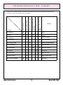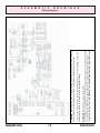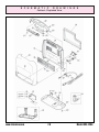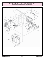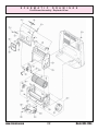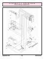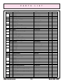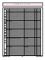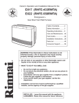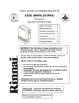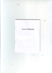
1
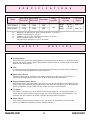
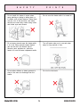
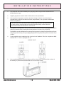
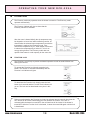
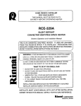
HOME OWNER/INSTALLER FOR YOUR SAFETY THIS MANUAL MUST BE READ IN ITS ENTIRETY BEFORE OPERATING HEATER RCE-229A SILENT SERVANT CONVECTOR VENT-FREE SPACE HEATER Owner’s Operation and Installation Manual THIS IS AN UNVENTED GAS-FIRED HEATER. IT USES AIR (OXYGEN) FROM THE ROOM IN WHICH IT IS INSTALLED. PROVISIONS FOR ADEQUATE COMBUSTION AND VENTILATION AIR MUST BE PROVIDED. REFER TO INSTALLATION INSTRUCTIONS ON PAGE 8. WARNING: IF THE INFORMATION IN THIS MANUAL IS NOT FOLLOWED EXACTLY, A FIRE OR EXPLOSION MAY RESULT CAUSING PROPERTY DAMAGE, PERSONAL INJURY OR LOSS OF LIFE. DO NOT STORE OR USE GASOLINE OR OTHER FLAMMABLE VAPORS AND LIQUIDS IN THE VICINITY OF THIS OR ANY OTHER APPLIANCE. WHAT TO DO IF YOU SMELL GAS • DO NOT TRY TO LIGHT ANY APPLIANCE. • DO NOT TOUCH ANY ELECTRICAL SWITCH; DO NOT USE ANY PHONE IN YOUR BUILDING. • IMMEDIATELY CALL YOUR GAS SUPPLIER FROM A NEIGHBOR'S PHONE. FOLLOW THE GAS SUPPLIER'S INSTRUCTIONS. • IF YOU CANNOT REACH YOUR GAS SUPPLIER, CALL THE FIRE DEPARTMENT. INSTALLATION AND SERVICE MUST BE PERFORMED BY A QUALIFIED INSTALLER, SERVICE AGENCY OR THE GAS SUPPLIER. INSTALLER: MUST LEAVE MANUAL WITH UNIT AFTER INSTALLATION. OWNER: RETAIN THIS MANUAL SAFELY, FOR FUTURE REFERENCE. T A B L E O F C O N T E N T S Page SPECIFICATIONS .................................................................................................3 SAFETY DEVICES ................................................................................................3 IMPORTANT POINTS ............................................................................................4 SAFETY POINTS ...................................................................................................5 USAGE AND INSTALLATION MUSTS ...................................................................7 INSTALLATION INSTRUCTIONS ..........................................................................8 OPERATING INSTRUCTION PLATE .....................................................................11 ADDITIONAL CUSTOMER OPERATING INFORMATION ..................................12 MAINTENANCE / SERVICE ................................................................................17 TROUBLE SHOOTING CHART ...........................................................................18 SCHEMATIC DRAWINGS/PARTS LIST ..............................................................................20 ERROR MESSAGES ...........................................................................................27 LIMITED WARRANTY .....................................................................................back cover WARNING IMPROPER INSTALLATION, ADJUSTMENT, ALTERATION, SERVICE OR MAINTENANCE CAN CAUSE PROPERTY DAMAGE, PERSONAL INJURY OR LOSS OF LIFE. REFER TO THE OWNER’S INFORMATION MANUAL PROVIDED WITH THIS APPLIANCE. INSTALLATION AND SERVICE MUST BE PERFORMED BY A QUALIFIED INSTALLER, SERVICE AGENCY OR THE GAS SUPPLIER. FOR ASSISTANCE OR ADDITIONAL INFORMATION CONSULT A QUALIFIED INSTALLER, SERVICE AGENCY OR THE GAS SUPPLIER. GENERAL INFORMATION THIS SERIES IS DESIGN CERTIFIED BY THE AMERICAN GAS ASSOCIATION LABORATORIES AS A VENT FREE CIRCULATOR AND MUST BE INSTALLED ACCORDING TO THESE INSTRUCTIONS. A N Y A LT E R AT I O N O F T H E O R I G I N A L D E S I G N I N S TA L L E D O T H E R THAN AS SHOWN IN THESE INSTRUCTIONS OR USED WITH A TYPE OF GAS NOT SHOWN ON THE RATING PLATE, IS THE RESPONSIBILITY OF THE PERSON AND COMPANY MAKING THE CHANGE. www.rinnaina.com 2 Model RCE-229A S P E C I F I C Input Rating Input Rating Thermostat Btuh HIGH Btuh LOW Model RCE-229A-N 6,000 2,000 YES RCE-229A-P 6,000 2,500 YES “-N” “-N” “-P” “-P” A T I O Weight in pounds S Dimensions in inches Height: Width: Depth: 13.4 N Fan CFM Output 14 9/16" 14 3/4" 6 11/16" High: 64 Low: 46 Models are for Natural Gas. (Inlet Pressure within 4.3"-10.5"W.C.) Models manifold pressure: 3.5"W.C. Models are for L. P. Gas. (Inlet Pressure within 4.7"-13"W.C.) Models manifold pressure: 4.4"W.C. Gas connection pipe size 1/2" N.P.T. all models. S A F E T Y D E V I C E S Overheat Switch When the heater gets too hot during operation (for example when the filters or air outlet louvers are blocked) this device turns the gas off automatically. Remove cause of overheat (clean filters) allow heater to cool, then re-ignite. Fuse The electrical circuits are protected by a fuse. When the fuse blows, the heaters will not operate at all. The fuse must be replaced by an authorized person. Flame Failure Device This device automatically cuts off the gas supply to the heater in the event of a gas failure. To restore the gas supply to the heater, turn it off, then follow the ignition procedure. Oxygen Depletion Safety Device If the oxygen level in the room drops below a pre-set limit, this device cuts the gas supply off to the heater. If the oxygen depletion device operates, turn the heater off, ventilate the room, then follow the ignition procedure to re-light. Heater will not re-light until room is fully ventilated. Tilt Switch If the heater is knocked over, the tilt switch will cut the gas supply off. The fan keeps running. To restore the gas supply, stand the heater upright, turn it off then follow the ignition procedure. The tilt switch may also operate if the heater is jolted or picked up while in operation. Power Failure In the event of a power failure or power cut, the gas valves will automatically close. After the power is re-instated the appliance must be restarted manually. Model RCE-229A 3 800-621-9419 I M P O R T A N T P O I N T S UNPACK HEATER: Check for damage. (DO NOT INSTALL DAMAGED HEATER.) If heater is damaged, contact your supplier for advice. Before installing a heater, check the label for the correct gas type (see label on side of heater). Refer to local gas authority for confirmation of gas type if you are in doubt. INCLUDED IN CARTON: Customers Operating Information/Manual Gas Valve IMPORTANT 1. The appliance must be installed in accordance with state and local codes. 2. For information on gas rate, see data plate on the appliance. 3. When using this appliance, ensure that the room is correctly ventilated. Check the local gas authority for information on ventilation requirements. 4. The heater must not be installed where curtains or other combustible materials could come into contact with it. In some cases, curtains may need restraining. It must also be 2" (50mm) clear of walls. 5. This appliance is not designed to be built in. 6. If you move, check the gas type in the area where you are moving to. The local gas authority will be able to advise on local regulations. 7. This heater discharges a large volume of warm air at low level to provide even heat distribution. If the air in the room contains cooking vapor or cigarette smoke, and the heater is used on a carpet, the surface of the carpet may become discolored. In addition, some nylon carpets contain dyes which may be affected by the warm air flow. Some soft vinyl surfaces are also subject to distortion, or discoloration by warm air. To prevent discoloration of carpets etc., a mat should be placed under the appliance, extending about 30"(750mm) in front of it. 8. This heater can be installed in a bathroom or a bedroom. When installed in a bathroom or a bedroom, the heater must be wall mounted with optional wall mounting kit. See page 26 of manual for part No. of wall mounting kit. www.rinnaina.com 4 Model RCE-229A S A F E T Y P O I N T S Do not install this heater in areas where spray painting or plating is taking place, or in places such as hair dressers, where there may be a lot of fluff and dust, and where aerosols are used. May create strong odors and irritate eyes and sinuses. Do not move the heater while it is turned on. Do not spray aerosols near this heater while it is in use. Many aerosols contain butane gas and can be a fire hazard. Use of aerosols, paint, polishes etc., while this heater is in use will cause unpleasant smells. Turn off heater when not in use and when away for long periods of time. Do not allow children or elderly persons to sleep in the warm air discharge from the heater. Do not sit on this heater. Model RCE-229A 5 800-621-9419 S A F E T Y P O I N T S Do not place wet articles on this heater, the water may drip into the electrical parts. Do not allow children to put articles in the louvers. Supervise children playing near this heater. Do not turn the heater off by unplugging it from the wall, or while the fan is cooling the heater off. (This heater is not suitable for use with a plug in type timer.) Ventilate the room when this heater is in use. Correct, fixed ventilation is usually sufficient, consult your local gas authority for local regulations. Keep away from flammable materials. Combustible materials must not be placed where the heater could ignite them. Do not place articles in front of the hot air discharge. Do not place containers of liquid on top of the heater. Water in the heater can cause extensive damage. www.rinnaina.com 6 Model RCE-229A U S A G E A N D I N S TA L L AT I O N M U S T S 1. Read these rules and the instructions carefully. Check all local codes. Failure to follow these could cause a malfunction of the heater resulting in death, serious bodily injury and/or property damage. 2. This heater is designed for use only with one type of gas, either L.P.G. or Natural Gas. Make sure that the type of gas to be supplied to this unit matches that shown on the rating plate on the heater. This unit is not convertible. 3. WARNING: Any change to this heater or its controls can be dangerous. 4. If a gas leak is suspected, turn heater off, turn gas supply valve off at regulator or appliance connecter valve. Open windows to ventilate area immediately and contact your dealer or gas company. 5. Installation and repair should be done by a qualified service person. Heater should be inspected before use and at least annually by a professional service person. More frequent cleaning may be required due to excessive lint from carpeting, bedding material, etc. It is imperative that control compartment, burners and circulating air passageways be kept clean. 6. Keep area near the heater clear and free from combustible materials, gasoline and other flammable vapors and liquids. 7. Due to its high temperature, the heater should be located out of traffic and away from furniture and draperies. 8. Do not place clothing or flammable material on or near the heater. 9. Any safety panel or guard removed for servicing must be replaced prior to operating the heater. 10. An unvented gas heater will increase the amount of humidity in the room. 11. This heater is intended for space heating purposes only. Do not use for other purposes such as drying clothes or baking paints. 12. Do not touch the outlet area while the heater is in use. To avoid burns, do not move the heater during use and avoid touching the heater just after turning off. 13. Children and adults should be alerted to the hazard of high surface temperatures and should stay away to avoid burns or clothing ignition. 14. Young children should be carefully supervised when they are in the same room with the heater. 15. L.P.G containers must not be installed indoors. 16. Do not install in a windy area such as facing a window or a door leading to the outside. 17. Do not use this room heater if any part has been under water. Immediately call a qualified service technician to inspect the room heater and to replace any part of the control system and any gas control which has been under water. 18. Carpet lint or cigarette smoke may pass through the heater, discolor, and be deposited into the room. 19. This unit discharges a large volume of warm air at a low level to provide even heat distribution. If the air in the room contains cooking vapors, cigarette smoke, and if used on carpet, the surface in front of unit is subject to discoloration. Some carpets contain dyes which can be effected by warm air flow and could discolor. To aid in prevention of discoloration, place a mat under the unit to extend to the front 30 “. Model RCE-229A 7 800-621-9419 I N S TA L L AT I O N I N S T R U C T I O N S NOTICE BEFORE INSTALLATION The heater must be installed by a qualified service person according to this installation instructions. When used without adequate combustion and ventilation heater air may give off carbon monoxide. Check your local building codes for the proper method of installation. In the absence of local codes, this heater installation must conform with American National Standard (National Fuel Gas Code) ANSI Z223.1. Available from the American National Standards Institute, Inc., 1430 Broadway, New York, NY 10018, or from the National Fire Protection Association, Batterymarch Park, Quincy, MA 02269. All correspondence should refer to Model No., Serial No., and type of gas. WARNING: Electrical Grounding Instructions This appliance is equipped with a three-prong (grounding) plug for your protection against shock hazard and should be plugged directly into a properly grounded three-prong receptacle. This appliance may be installed in an aftermarket manufactured (mobile) home where not prohibited by state or local code. Aftermarket = completion of sale, not for purpose of resale from manufacturer. This heater shall not be installed in a confined space or unusually tight construction unless provisions are provided for adequate combustion and ventilation air. The National Fuel Gas Code ANSI Z223.1 defines a confined space as a space whose volume is less than 50 cubic feet per 1,000 Btu per hour (4.8m3 per kW) of the aggregate input rating of all appliances installed in that space and an unconfined space as a space whose volume is not less than 50 cubic feet per 1,000 Btu per hour (4.8m3 per kW) of the aggregate input rating of all appliances installed in that space. Rooms communicating directly with the space in which the appliances are installed, through openings not furnished with doors, are considered a part of the unconfined space. The following formula can be used to determine the maximum heater rating per the definition of unconfined space: BTU/HR = (L1 +L2)Ft X (W)Ft X (H) Ft X 1000 50 Consider two connecting rooms with an open area between, with the following dimensions: BTU/HR = (15 1/2+12) X (12) X (8) X 1000 50 = 52800 BTU/HR If there is a door between the two rooms that can be closed the calculation must be based only on the room with the heater. BTU/HR = (15 1/2) X (12) X (8) X 1000 50 = 29760 BTU/HR WARNING: If the area in which the heater may be operated is smaller than that defined as an unconfined space or if the building is of unusually tight construction, provide adequate combustion and ventilation air by one of the methods described in the National Fuel Gas Code, ANSI Z223.1, Section 5.3 or applicable local codes. www.rinnaina.com 8 Model RCE-229A I N S TA L L AT I O N I N S T R U C T I O N S Unusually tight construction is defined as construction where: a) Walls and ceilings exposed to the outside atmosphere have a continuous water vapor retarder with a rating of 1 perm (6X10-11kg per pa-sec-m2) or less with openings gasketed or sealed, and b) Weather stripping has been added on openable windows and doors, and c) Caulking or sealants are applied to areas such as joints around window and door frames, between sole plates and floors, between wall-ceiling joints, between wall panels, at penetrations for plumbing, electrical, and gas lines, and at other openings. LOCATION AND CLEARANCES 1. The minimum clearances from the combustible materials areas follows: 2 inches from top 2 inches from back 2 inches from side 30 inches from front 0 inches from bottom 2. This heater may be installed on combustible flooring. When the heater is installed directly on carpeting, tile or other combustible material other than wood flooring, the heater shall be installed on a metal or wood panel extending the full width and depth of the heater. 3. Adequate clearances for accessibility for purposes of servicing and proper operation must be provided. 4. Adequate clearances around air openings must be provided. 5. Right and left sides are determined when facing the front. 6. Do not install in areas where curtains, drapes, clothing, or other moving flammables are within 12 inches of this unit. 7. This unit is designed to mount directly to a wall with optional wall mounting kit. See page 24 for part No. of wall mounting kit. 8. Make certain of adequate combustion and ventilation air. 9. Do not oversize the heater to the room. GAS CONNECTION 1. The gas supply line shall be gas-tight, sized and so installed as to provide a supply of gas sufficient to meet the maximum demand of the heater without loss of pressure. 2. A shut off valve (or appliance connector valve) should be installed in the upstream of the gas line to permit servicing. 3. Flexible pipe and any appliance connector valve used for gas piping shall be types approved by nationally recognized agencies. Model RCE-229A 9 800-621-9419 I N S TA L L AT I O N I N S T R U C T I O N S 4. Any compound used on the threaded joint of gas piping shall be a type which resists the action of liquefied petroleum gas. 5. Supplied gas pressure must be within the limits shown in the specifications. 6. After completion of gas pipe connections, all joints including the heater must be checked for gas-tightness by means of leak detector solution, soap and water, or an equivalent nonflammable solution, as applicable. CAUTION: Since some leak test solutions, including soap and water, may cause corrosion or stress cracking, the piping shall be rinsed with water after testing, unless it has been determined that the leak test solution is noncorrosive. 7 The appliance and its appliance main gas valve must be disconnected from the gas supply piping system during any pressure testing of that system at test pressures in excess of 1/2 psi (3.5kPa). The appliance must be isolated from the gas supply piping system by closing its equipment shut-off valve during any pressure testing of the gas supply piping system at test pressures equal to or less than 1/2 psi (3.5kPa). 8. A valve supplied must be installed on back of unit at time of installation. This is for compliance to ANSI standard Z21.11.2. Valve is packaged with unit. MANUAL VALVE CLOSED 9. OPEN After completing pipework, secure the heater to the floor. Use the two screws provided, as shown in the drawing. To prevent deforming base plate, do not over torque screws. www.rinnaina.com 1 0 Model RCE-229A I N S TA L L AT I O N I N S T R U C T I O N S OPERATING INSTRUCTION PLATE CONVECTOR RCE-229A FOR YOUR SAFETY READ BEFORE OPERATING WARNING: If you do not follow these instructions exactly, a fire or explosion may result causing property damage, personal injury or loss of life. A. This appliance does not have a pilot. It is equipped with an ignition device which automatically lights the burner. Do not try to light the burner by hand. B. BEFORE OPERATING smell all around the appliance area for gas. Be sure to smell next to the floor because some gas is heavier than air and will settle on the floor. • If you cannot reach your gas supplier, call the fire department. C. Use only your finger to push with. Never use tools. If the button will not reactivate by touch, don’t try to repair it, call a qualified service technician. Force or attempted repair may result in a fire or explosion. D. Do not use this appliance if any part has been under water. Immediately call a qualified service technician to inspect the appliance and to replace any part of the control system and any gas control which has been under water. WHAT TO DO IF YOU SMELL GAS. • Do not try to light any appliance. • Do not touch any electrical switch; do not use any phone in your building. • Immediately call your gas supplier from a neighbor’s phone. Follow the gas supplier’s instructions. OPERATING INSTRUCTIONS • 1. 2. 3. STOP! Read the safety information above on this label. This appliance is equipped with an ignition device which automatically lights the burner. Do not try to light the burner by hand. Turn off all electric power to the appliance via the ON/OFF button on the control panel. Locate manual gas valve to be found on back side of heater. Turn Manual valve clockwise to the full OFF position. Wait five (5) minutes to clear out any gas. Then smell for gas, including near the floor. If you then smell gas, STOP! Follow “B” in the safety information above on 4. 5. 6. 7. 8. 9. 10. this label. If you don’t smell gas, go to next step. Turn Manual gas valve to the full ON position. Turn on all electric power to the appliance. Press ON/OFF button to “ON”. Set the thermostat to desired setting. Burner is lit when operation lamp glows red. If operation lamp is flashing red, burner has not been lit. If the appliance will not operate, follow the instructions “To turn off gas to appliance” and call your service technician or gas supplier. Room Temperature Display Filter Warning Lamp MANUAL VALVE CLOSED OPEN Temperature Down Temperature Up Function Lock Ignition Button TO TURN OFF GAS TO APPLIANCE 1. 2. Turn off electric power to the appliance using the ON/ OFF switch located on the control panel. Turn manual valve clockwise to the full OFF position. WARNING: Improper installation, adjustment, alteration, service or maintenance can cause personal injury or loss of life. Refer to the owner’s information manual provided with this appliance. Installation and service must be performed by a qualified installer, service agency or the gas supplier. NOTE: The fan will continue to operate until the appliance is cool, do not turn the appliance off by unplugging it from the wall. Keep burner and control compartment clean. See installation and operating instructions accompanying heater. Model RCE-229A 1 1 800-621-9419 ADDITIONAL CUSTOMER OPERATING INFORMATION INSTALLATION Make certain the heater is connected intoboth the gas and the electric power. Check room size and ventilation. Do not oversize. Improper sizing may cause nuisance lock outs. CONTROL PANEL LAYOUT ON TIMER INDICATOR TIME/TEMP DISPLAY Indicates that the ON Timer mode is in operation. Shows either the temperatures or coded error messages. FILTER INDICATOR Indicates that the filter needs cleaning. AUTO-OFF INDICATOR Indicates the thermostat-off function is activated. COMBUSTION INDICATOR Indicates that the burner is alight and the appliance is heating the room. INDICATORS OFF TIMER INDICATOR ECONOMY INDICATOR Indicate what information is currently displayed on the LED display. Indicates that the OFF Timer mode is in operation. Indicates that the Economy mode is in operation. OFF TIMER BUTTON TIME/TEMP ADJUSTMENT S e l e c ts o p e r a t i n g m o d e f o r d e l a y O F F Ti m e r function. Increases or decreases the temperature setting as well as changing hours or minutes. AUTO-OFF BUTTON Selects the thermostat-off function. www.rinnaina.com ON/OFF BUTTON Main switch for turning O N / O F F. ON TIMER BUTTON Selects operating mode for delay ON Timer function. FUNCTION LOCK INDICATOR Indicates Function lock is activated. 1 2 FUNCTION LOCK Locks all controls when pressed. (Except OFF) Model RCE-229A O P E R AT I N G Y O U R N E W R C E - 2 2 9 A TURNING ON Press the ON/OFF button to operate the heater. The ON indicator will glow green. After approximately 20 seconds the spark generator will be heard before the burner ignites and the ON indicator glows red, indicating that the burner is alight. Warm air can be felt coming from the louvres 15 seconds later. If the heater does not ignite on initial use, this may be due to air remaining in the gas supply line. The spark generator will only continue for 15 seconds. After this it will be necessary to press the ON/OFF button OFF, then ON again. TURNING OFF Simply press the ON/OFF button to switch off the heater. The ON indicator will go out. The convection fan will continue to operate for several minutes after the burner has gone out in order to cool the appliance. Do not unplug the appliance while the convection fan is running. DO NOT turn heater off by unplugging at the power point. The convection fan will continue to run until the appliance cools. ROOM TEMPERATURE ADJUSTMENT The room temperature and pre-set temperatures can only be displayed and adjusted when the heater is running. Press the “S” button to increase the temperature setting or “T” button to decrease the temperature setting. The temperatures can be preset to: a) [L] low (about 50°F) b) [60°F] to [80°F] in 2°F increments c) [H] (continuously high) If the heater does not ignite then the pre-set temperature may not be set to a setting which is higher than the actual room temperature. AUTO-OFF FUNCTION When you select AUTO-OFF, the indicator light will glow. You have selected a Full Thermostat Control Function. The heater will cycle High, Low and OFF to maintain the selected room temperatures. When the AUTO-OFF indicator is not glowing, you have selected a manual off mode of operation. The unit will continue to produce at least 2000 BTU/h of heat until you cut the unit off manually. Model RCE-229A 13 800-621-9419 OPERATING YOUR NEW RCE-229A ECONOMY MODE The Economy mode only operates when the heater is turned on. The Economy mode operates automatically. The Economy indicator will glow to show that the Economy function is activated. After the room is heated initially the air temperature may be dropped to a lower level without affecting comfort. 30 minutes after the selected room temperature (set with the thermostat) is reached, the Economy mode, if set, reduces the temperature by 2°F. After another 30 minutes it reduces the temperature by a further 2°F, this is an energy saving feature. The Economy mode does not operate if the heater is under capacity for the room size. FUNCTION LOCK The Function Lock will help to prevent accidental operation as well as small children from altering the controls. To operate the Function Lock simply press the Lock button. The function is activated immediately and the Function Lock indicator will glow. To deactivate the Function Lock simply press the Lock button for 2 seconds and the Function Lock indicator will go out. The lock can be deactivated at any time in this way. During normal operation the Function Lock may be activated and all controls other than the OFF switch will be locked. Deactivating the lock releases the controls. If the lock is activated while the heater is turned OFF, then all functions will be locked. If the heater is turned OFF while the Function Lock is activated, it cannot be turned ON again until the lock is deactivated. www.rinnaina.com 1 4 Model RCE-229A T I M E R O P E R A T I O N OFF TIMER OPERATION This feature is useful on cold nights when the unit continues to operate after you have gone to bed. The OFF Timer can be selected when the heater is operating manually, in OFF, or in ON Timer mode. When the OFF Timer feature is selected, the heater will automatically switch off after 60 minutes. 1 Press the OFF Timer button. The OFF Timer indicator lights up. The heater will operate at the preset temperature selected in the system memory. The temperature will automatically run at 80°F if the set temperature is “H”. If selected while the ON Timer is set, the heater will come on and run for 60 minutes, after which it will remain in ON Timer standby mode. If the ON Timer is selected after the OFF Timer has been selected, the unit will run for 60 minutes (OFF Timer mode ) and then remain in the ON Timer standby mode. In all cases where the ON and OFF Timers are selected together, the OFF Timer will take precedence and run the heater for 60 minutes after which the heater will remain in the ON Timer standby mode. OFF TIMER STOPS AFTER 1 HOUR. Five minutes before the finish of the OFF Timer, the OFF Timer indicator will flash, indicating that the function is nearing completion. The OFF Timer indicator will then go out at completion of the 60 minute time delay. In cases where both the ON and OFF Timers are selected, once the OFF Timer has run the heater for 60 minutes, the ON Timer indicator will remain alight and the heater will be in ON Timer standby mode. To cancel the OFF Timer, press either the ON-OFF button or the OFF Timer button at any time. ON TIMER OPERATION The ON Timer allows you to program the heater to turn on after a pre-determined time period. As an example, if the time now is 10:30 pm and you wish the heater to start at 6:00 am tomorrow morning, then the ON Timer must be set to 7.5(hours). The ON Timer preset times are from 30 minutes to 24 hours. These times can be selected in 30 minute increments up to 10 hours and then 1 hour increments up to the maximum of 24 hours. BEFORE SELECTING THE ON TIMER CONFIRM: That the desired preset room temperature has been set (see page 13) Model RCE-229A 15 800-621-9419 T I M E R O P E R A T I O N WARNING y y 1 Ensure there are no obstacles or foreign materials directly in front of the appliance where the warm air will discharge into the room. Ensure the appliance is not positioned where warm air discharge will blow directly on someone sleeping. Press the “ON Timer” button The “ON Timer” and “ON/Combustion” (green) indicators will light up. A preset time will be displayed on the digital monitor.(The first time the ON Timer is preset, this time will be “8.0”) The ON Timer can be selected while the unit is in operation, or while it is off (if set during operation, pressing the ON Timer button will stop the unit heating and the ON/Combustion indicator will change from red to green). The appliance will remain in standby mode. 2 Presetting the time Pressing the “T” or “S” buttons alters the preset time. After 10 seconds the digital monitor will go out. If the display has gone out: Pressing the “T” or “S” buttons once will show the remaining time on the digital monitor. Pressing the button more than once will alter the preset time. 3 The heater will operate after reaching the end of the preset time. “ON/Combustion” Indicator glows red. The heater will operate at the preset temperature selected in the system memory. The heater will automatically operate at 80°F if the preset temperature is set to “H”. 4 The heater stops automatically after 1 hour. The”ON Timer” indicator will flash to indicate that heating is about to stop (at approximately 55 minutes). After another 5 minutes the heater will automatically stop heating and turn off completely. The “ON Timer” indicator will continue to flash until the heater is manually operated again. The “ON/ Combustion” indicator will go out. Pressing the ON-OFF button will turn off the ON Timer indicator. TO CANCEL THE ON TIMER Press the “ON Timer” button or press the “ON-OFF” button. The setting will be cancelled and the timer indicators will go out. The ON Timer will be cancelled if the power plug is removed from the power point, a power failure while the appliance was in standby mode, or if the ON Timer setting is cancelled. “00” will flash on the digital monitor when power is reinstated. Pressing the ON button and starting the unit will delete the “00”. www.rinnaina.com 1 6 Model RCE-229A M A I N T E N A N C E / S E R V I C E MAINTENANCE SUGGESTIONS This heater has been designed and constructed for a long performance life when installed and operated properly under normal conditions. Regular inspections, as outlined in this section, are strongly recommended as means of keeping your heater operating efficiently and safely throughout the season. Access to internal parts is from the front of the heater. 1. Cleaning Clean air filter at least once a week. Do not wait for filter warning lamp to come on before cleaning filter. Do not use the heater with the filter warning lamp on, this may cause it to overheat. Dusty filter reduces the air flow through the heater, as well as, reducing the heater’s effectiveness. Clean filter with air pressure or vacuum cleaner. Heater must be cleaned annually. Keep heater clear of dust and debris especially in and around the ODS burner. Cleaning procedures of heater are as follows: 1) Turn heater off. Unplug electric cord and allow to cool for one hour. 2) Remove the two(2) screws that hold the louver and two(2) screws at the bottom of the left and right hand side panel. 3) Use pressurized air to remove dust from around burner and electrical components. Apply air pressure with nozzle to five(5) holes on combustion chamber cover. (See page 24 of schematics, part #RC-219-31, key #117-1) 4) All outside parts of the heater can be cleaned using soap and water on a soft damp cloth. DO NOT DAMAGE OR DISTORT ANY PARTS OF HEATER. DO NOT USE WET CLOTH OR SPRAY CLEANERS ON BURNER. UNIT SHOULD BE CHECKED AND CLEANED ANNUALLY BY A PROFESSIONAL. TROUBLE SHOOTING STEP 1: 1) Be sure the heater is properly installed. See Section 2. INSTALLATION. 2) Make sure gas valve on L.P. Gas bottle or gas supply line is ON and gas pressure is available. 3) Make a careful visual inspection of all electrical connection and wiring. STEP 2: If the trouble persists after checking step 1, please check the cause of trouble in the following trouble shooting chart and correct it by following the procedures shown. Model RCE-229A 1 7 800-621-9419 T R O U B L E S H O O T I N G C H A R T Ɣ Power Cut Ɣ Ɣ (Initial Installation) Air in Gas Pipe Smell of Gas Ɣ Combustion Stops During Operation Burner Doesn't Ignite Not Plugged In Cause Filter Warning Lamp Glows No ON Indicator Problem Takes too Long to Warm the Room Please note: General cleaning, maintenance and wear and tear are not necessarily covered under the guarantee. Calls of this nature may be chargeable. Plug In Re-Ignite manually after power is restored Ɣ Ɣ Purge air (installer) Ɣ Room too Large Ɣ Dust on the Air Filter Remedy Check with retailer Clean the air filter (weekly) Louver Obstructed Ɣ Ɣ Clean obstruction Air Filter Blocked Ɣ Ɣ Clean filter (weekly) Ɣ Gas Escape Service call ON Timer is Set Ɣ Cancel ON Timer Function Lock Set Ɣ Cancel Function Lock Ɣ Turn gas on Gas Turned Off at Meter www.rinnaina.com Ɣ 1 8 Model RCE-229A Model RCE-229A 19 WARNING: Electrical Grounding Instructions This appliance is equipped with a three-prong (grounding) plug for your protection against shock hazard and should be plugged directly into a properly grounded three-prong receptacle. DO NOT CUT OR REMOVE THE GROUNDING PRONG FROM THIS PLUG! If any of the original wire as supplied with the appliance must be replaced, it must be replaced with a wire of at least a 194°F temperature rating. CAUTION: Label all wires prior to disconnecting when servicing controls. Wire errors can cause improper and dangerous operation. Verify proper operation after servicing. S C H E M A T I C D R A W I N G S Wiring Diagram 800-621-9419 S C H E M A T I C D R A W I N G S Cabinet - Exploded View www.rinnaina.com 20 Model RCE-229A S C H E M A T I C D R A W I N G S Gas Valve/Burner Assembly - Exploded View Model RCE-229A 2 1 800-621-9419 S C H E M A T I C D R A W I N G S Fan Blower Assembly - Exploded View www.rinnaina.com 22 Model RCE-229A S C H E M A T I C D R A W I N G S Electrical Wiring - Exploded View Model RCE-229A 23 800-621-9419 P A 001 002 003 004 005 006 007 008 009 100 No. 001-1 001-2 001-3 005-1 005-2 007-1 007-2 009-1 009-2 100-1 100-2 101 102 103 104 105 104-1 104-2 105-1 105-2 106 107 108 109 110 111 112 113 114 115 116 117 118 119 120 107-1 107-1 107-2 112-1 112-2 112-3 113-1 113-2 115-1 115-2 117-1 117-2 118-1 118-2 R T S PART NAME FRONT PANEL I SCREW SCREW LOUVER ASS'Y REAR PANEL G TC CHECK HOLDER TOP PLATE SCREW AIR FILTER TOP PLATE COVER SCREW TOP PLATE COVER SHEET BASE SCREW SECONDARY AIR COVER SCREW BURNER ASS’Y BURNER ASS'Y GAS CONTROL ASS'Y O-RING CONNECTION PIPE ASS'Y SCREW INJECTOR HOLDER SCREW INJECTOR INJECTOR DAMPER DAMPER SCREW O-RING BLIND SCREW PACKING FILTER GAS INLET FLANGE SCREW SCREW BURNER LID SCREW ELECTRODE ELECTRODE BRACKET SCREW SILICON TUBE COMBUSTION CHAMBER COVER SCREW COMBUSTION CHAMBER COVER LID SCREW HEAT SHIELD SEPARATION BOARD www.rinnaina.com 24 L I S T PART No. RC-219-50-9 ZFAB0410SC ZFAB0408SC RC-219-46-5 RC-219-42-7 RC-334-73-1 RC-229-516-SP ZFAB0410SC RC-219-29 RC-219-52 CP-30486-2 RC-219-56 RC-219-41-5 ZFAB0410SZ RC-219-38 CP-30518-1 B6C1-1-1 B6C1-1-2 C36D-3-6-S M10B-1-10 RC-229-512 ZHAA0406SZ RC-208-22 ZFAB0410SZ RC-208-11-2-1.20 RC-208-11-1-0.90 RC-208-23-20 RC-208-23-19 ZFAB0408SZ M10B-13-14 AU39-965 C3I1-7 RCK-6808 431F-1110-2 ZHAA0412SZ ZBA0408SC RC-219-39 ZFAB0408SZ RC-328-32-2 RC-334-136 ZFAB0408SZ RC-223-84-b RC-219-31 ZFAB0408SZ RC-352-29 ZFAB0408SZ RC-219-35 RC-219-37 QTY. 1 2 2 1 1 1 1 4 1 1 2 1 1 5 1 4 1 1 1 2 1 2 1 2 1 1 1 1 1 1 1 1 1 1 2 4 1 1 1 1 2 1 1 6 1 1 1 1 REMARKS NG LPG NG LPG NG LPG Model RCE-229A P A 121 No. 121-1 121-2 121-3 122 123 124 125 126 128 131 132 134 135 136 137 138 139 140 141 142 143 144 123-1 123-2 125-1 125-2 128-1 128-2 134-1 134-2 135-1 135-2 137-1 137-2 138-1 138-2 140-1 140-2 142-1 142-2 143-1 143-2 143-3 144-1 144-2 700 701 702 703 700-1 700-2 700-3 700-4 700-5 700-6 701-1 701-2 701-3 703-1 703-2 R T S PART NAME COMBUSTION CHAMBER ASS'Y SCREW SCREW TC SPACER TC SPACER THERMOCOUPLE BRACKET SCREW THERMOCOUPLE TOTAL ASS'Y THERMOCOUPLE FIXER SCREW CONVECTION FAN BEARING SCREW CLAMP NYLON TACK SUB P.C.B. BRACKET SCREW POWER SUPPLY CABLE BRACKET SCREW VALVE COVER CONNECTION PIPE FIXER SCREW OVER HEAT SWITCH SCREW CIRCUIT BOARD SPACER OUTLET SCREW CABLE CLIP THERMISTOR HOLDER SCREW CONVECTION FAN TOTAL ASS'Y SCREW SCREW PLATE HOLDER SCREW P.C.B. ASS'Y P.C.B. P.C.B. FIXER SCREW SCREW IGNITER ASS'Y SCREW SUB P.C.B. CURRENT FUSE SCREW TF HARNESS POWER SUPPLY CORD SCREW Model RCE-229A L I S PART No. RC-219-30 ZFAB0408SZ ZFAB0408SC RC-209-68-1 RC-209-68-2 RC-152-224 CP-30523-2 RC-511-66-1 RC-210-89-2 ZFAB0406SZ RC-229-13 RC-223-74 ZFAB0406SZ CP-90312 RC-215-24-1 RC-229-1013 ZFAB040BSZ RC-329-1033 ZFDB0408SB RC-606-96 RC-208-21 ZFAB0408SZ ES-01183 CP-30518-1 CP-90436-3 RC-229-511 ZHAA0412SZ CP-90125-2 RC-229-540 ZFAB0408SB RC-229-523 ZFAB0408SC ZFAB0408SZ RC-229-539 ZFDB0410SB RC-229-514 ED-247-V1 RC-229-513 ZGAA0308SZ ZFAB0410SZ EI-181-1 CP-30421-1 ED-189 EP-102-13 CP-30421-1 RC-229-530 CP-90466-1 CP-30421-1 25 T QTY. 1 2 2 1 1 1 2 1 1 1 1 1 2 1 1 1 1 1 1 1 1 1 1 2 4 1 2 2 1 1 1 4 2 2 2 1 1 1 4 1 1 1 1 1 1 1 1 1 REMARKS NG, LPG LPG 250V 3A 800-621-9419 P A R T S L I S 802 803 804 901 902 903 PART NAME CONVECTION FAN MOTOR ASS'Y THERMISTOR TC CHECK LEAD WIRE MVIG HARNESS TRANSFORMER SCREW OVER HEAT THERMISTOR SCREW OPERATION P.C.B. SCREW OWNER'S INFORMATION MANUAL RATING PLATE RATING PLATE CAUTION PLATE OPERATING PLATE WIRING DIAGRAM ANCHOR SCREW MANUAL VALVE ASS'Y PART No. RC-229-524 RC-511-65-3 RC-606-11-1 RC-229-529 ET-250 ZFAB0408SZ RC-241-70 ZFAB0408SZ RC-229-517 ZGAA0308SZ RC-229-521 RC-229-527-1 RC-229-527-2 RC-229-525 RC-229-538 RC-229-520 AU 102-902 CP-30408 BRR37-244 904 WALL BRACKET KIT (OPTION) RC-229-550 No. 704 705 706 707 709 710 711 800 801 709-1 709-2 710-1 710-2 711-1 711-2 www.rinnaina.com 26 T QTY. REMARKS 1 1 1 1 1 1 1 1 1 5 1 1 NG 1 LPG 1 1 1 2 2 1 1 Model RCE-229A E R R O R M E S S A G E S This heater has the ability to check its own operation continuously. If a fault occurs, an Error Message will flash on the Digital Display of the control panel. This assists with diagnosing the fault, and may enable you to overcome a problem without a service call. Please quote the code displayed when inquiring about service. CODE DISPLAYED FAULT Tilt Switch Activated REMEDY Turn heater ON, after setting heater upright. Miss Ignition Check gas is turned ON. Service call if repeated. Flame Failure Ventilate the room. Service call if repeated. Back Fire Sensor Activated Overheat Room Overheat Power cut Turn heater OFF, after a while ON again. Service call if repeated. Clean filter. Service call if repeated. Service call. Turn heater OFF, then ON again. If you see other codes displayed, contact Rinnai or your nearest service agent and arrange for a service call. In all cases, you may be able to clear the Error Message simply by turning the heater OFF, then ON again. If the Error Message still remains or returns on the next operation, contact RInnai or your nearest service agent and arrange for a service call. 27 LIMITED WARRANTY RINNAI SPACE HEATERS Rinnai America Corporation warrants the products described in this warranty including any parts and components thereof, to be free from any defects in materials and workmanship for the period specified below, subject to the terms specified in this warranty. This warranty gives you specific legal rights and you may also have other rights which vary from state to state. This warranty extends to the original purchaser. MODEL PERIOD OF COVERAGE TYPE OF FAILURE COVFRFD SILENT SERVANT RCE-229A THREE YEARS FROM DATE OF PURCHASE DEFECTIVE MATERIALS AND WORKMANSHIP In the event of a malfunction, operational difficulty or failure of the product, or any parts or components, during the warranty term, resulting from defects in materials of workmanship Rinnai will remedy the malfunction, operational difficulty, or failure without charge to the owner. The remedy will consist of repair or replacement of the product (including payment of reasonable shipping costs) at the option of Rinnai. You may obtain the benefits of warranty coverage by returning the product to a qualified Rinnai servicing agent which has been qualified by Rinnai or its authorized distributor. Any such warranty replacement or repair shall be subject to the terms and conditions of this warranty for the remainder of the original period of coverage. In order to obtain the name and location of the qualified Rinnai servicing agent closest to you, please write Rinnai at the address shown on the back side of the warranty card or call Rinnai at 1-800-621-9419. This warranty does not cover any failure, operational difficulty, or malfunction due to accident, abuse, misuse, alteration, Acts of God, misapplication, improper installation or improper maintenance or service, or from any cause other than defects in materials and workmanship. Any implied warranties of merchantability and fitness applicable to the equipment are limited in duration to the period of coverage of this express written warranty. Some states do not allow limitations on how long an implied warranty lasts, so this limitation may not apply to you. Rinnai is not liable for any special, indirect or consequential damages; some states do not allow the exclusion or limitation of incidental or consequential damages, so this limitation may not apply to you. Rinnai does not authorize any person or company to assume for it any other obligation or liability in connection with the sale, application, engineering, installation, use, removal, return, or replacement of its products; and no such representatives are binding on Rinnai. The Warranty Registration Card provided below should be returned within two weeks of purchase to help Rinnai better serve you. However, the return of the Registration Card is not necessary in order to validate this warranty. EXTENDED WARRANTIES ARE AVAILABLE,CONTACT RINNAI FOR DETAILS. SPACE HEATER WARRANTY REGISTRATION CARD Owner’s Name _______________________________________________________ Installation Address ___________________________________________________ City, State, Zip________________________________________________________ Dealer’s Name Address ________________________________________________ City, State, Zip________________________________________________________ Type of Dealer _______________________________________________________ Model _________________________ Type of Gas _________________________ Serial No. ______________________ Date Purchased _________________ Comments: __________________________________________________________ ____________________________________________________________________ PLEASE RETURN THIS CARD TO RINNAI WITHIN TWO WEEKS OF PURCHASE AMERICA CORPORATION 103 International Drive Peachtree City, Georgia 30269 Phone: 1-800-621-9419 RC-229-521 Printed in Japan 2002.2