1
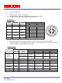
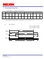
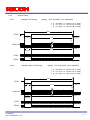
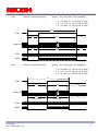
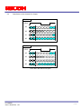
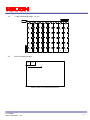
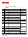
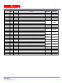
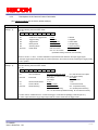
Small Cubic Type
VGA CCD
Monochrome PoCL Camera Link Camera
FV-L030B1
User’s Guide
RICOH COMPANY, LTD.
FV-L030B1
User’s Guide Rev. 1.01
1/32
Tables of Contents
1
Connector Specifications..................................................................................................................................... 3
1.1
1.2
2
Camera Link Connector...................................................................................................................................... 3
Power-I/O Connector .......................................................................................................................................... 4
Camera Output Timing Charts............................................................................................................................. 5
2.1
Normal Mode (Setting 10H: 1XX0XXXX)......................................................................................................... 5
2.1.1
Horizontal Timing......................................................................................................................................... 5
2.1.2
Vertical Timing ............................................................................................................................................. 6
2.1.2.1
Normal Full Scanning (setting 10H: 1XX00XXX, 11H: XXX0X000) .................................................. 6
2.1.2.2
Partial Full Scanning (setting 10H: 1XX01XXX, 11H: XXX0X000).................................................... 6
2.1.2.3
1/2 Partial Scanning (setting 10H: 1XX01XXX, 11H: XXX0X001) .................................................... 7
2.1.2.4
1/4 Partial Scanning (setting 10H: 1XX01XXX, 11H: XXX0X010) .................................................... 7
2.1.2.5
Variable Partial Scanning (Setting 10H: 1XX01XXX, 11H: XXX0X111).......................................... 8
2.2
Binning Mode (setting 10H: 1XX1XXXX) ...................................................................................................... 9
2.2.1
Horizontal Timing......................................................................................................................................... 9
2.2.2
Vertical Timing ........................................................................................................................................... 10
2.2.2.1
Binning Full Scanning (setting 10H: 1XX10XXX, 11H: XXX0X000)................................................ 10
2.2.2.2
Binning Partial Full Scanning (setting 10H: 1XX11XXX, 11H: XXX0X000)..................................... 10
2.2.2.3
Binning 1/2 Partial Scanning (setting 10H: 1XX11XXX, 11H: XXX0X001)...................................... 11
2.2.2.4
Binning 1/4 Partial Scanning (setting 10H: 1XX11XXX, 11H: XXX0X010)...................................... 11
2.3
Data Order on the Camera Link Output............................................................................................................ 12
2.4
1 Taps Transferring Image(1X-1Y)............................................................................................................... 13
2.5
Pixel Transferring Image................................................................................................................................... 13
3
Camera Operational Mode ................................................................................................................................. 14
3.1
Normal Mode .................................................................................................................................................... 14
3.1.1
Frame Exposure ........................................................................................................................................ 14
3.1.2
Electric Shutter .......................................................................................................................................... 14
3.2
Pulse Width Trigger Mode ................................................................................................................................ 15
3.2.1
Pulse Width Trigger Mode(V-Reset) ..................................................................................................... 15
3.2.2
Pulse Width Trigger Mode (Non-Reset) .................................................................................................... 16
3.2.3
Exposure Timing........................................................................................................................................ 16
3.3
Edge Preset Trigger Mode................................................................................................................................ 17
3.3.1
Edge Preset Trigger Mode (V-Reset) ........................................................................................................ 17
3.3.2
Edge Preset Trigger Mode (Non-Reset).................................................................................................... 18
3.3.3
Exposure Timing........................................................................................................................................ 18
3.4
H Reset Mode................................................................................................................................................... 19
4
Communication Protocol ................................................................................................................................... 20
4.1
Communication Method.................................................................................................................................... 20
4.2
Communication Settings................................................................................................................................... 20
4.3
Communication Format .................................................................................................................................... 20
4.4
Camera Control Command............................................................................................................................... 23
4.4.1
Camera Command List ............................................................................................................................. 23
4.4.2
Descriptions of the Camera Control Commands....................................................................................... 25
FV-L030B1
User’s Guide Rev. 1.01
2/32
1
1.1
Connector Specifications
Camera Link Connector
SDR (3M) or equivalent
This product is a PoCL type.
When a frame grabber is PoCL compliant, DO NOT SUPPLY POWER FROM THE I/O CONNECTOR.
When a frame grabber is NOT PoCL compliant, supply power from the I/O connector.
Pin Assignment
Pin No.
Signal Name
Pin No.
Signal Name
1
+12V
14
GND
2
X0-
15
X0+
3
X1-
16
X1+
4
X2-
17
X2+
5
Xclk-
18
Xclk+
6
X3-
19
X3+
7
SerTC+
20
SerTC-
8
SerTFG-
21
SerTFG+
9
CC1-(TRG)
22
CC1+(TRG)
10
CC2+
23
CC2-
11
CC3-
24
CC3+
12
CC4+
25
CC4-
13
GND
26
+12V
FV-L030B1
User’s Guide Rev. 1.01
3/32
1.2
Power-I/O Connector
HR10A-7R-6PB(Hirose)or equivalent
This connector is for the power supply (12Vdc) and input /output signals.
Use HR10A-7P-6S (Hirose) or equivalent for the cable side.
Pin Assignment
Pin No.
Signal Name
IN / OUT
1
GND
IN
2
I/O-1
IN/OUT
3
I/O-2
IN/OUT
4
I/O-3
Voltage
Low Voltage
High Voltage
0V
IN/OUT
5
I/O-4
IN/OUT
6
+12Vdc
IN
IN
0 to +0.5
+2.5 to +5.0V
OUT
0V
+3.3V
IN
0 to +0.5
+2.5 to +5.0V
OUT
0V
+3.3V
IN
0 to +0.5
+2.5 to +5.0V
OUT
0V
+3.3V
IN
0 to +0.5
+2.5 to +5.0V
OUT
0V
+3.3V
+12Vdc
Input/output signals can be assigned through the camera setting communication (see table 4).
Trigger input signal can be assigned either on Camera Link connector (CC1) or on the No. 2 pin of the IO
connector through the camera setting communication.
IO Signal Patterns
Command No.
F0H[3..0]
11H[7]
0
Option 0
0H
(Initial Setting)
(initial setting)
1
HR10A-7R-6PB (Hirose)
No.2 Pin
No.3 Pin
No.4 Pin
No.5 Pin
I/O-1 (SP4)
I/O-2 (SP3)
I/O-3 (SP2)
I/O-4 (SP1)
IN/TRG
IN/-
IN/-
IN/TRG
OUT/VD
OUT/HD
OUT/
STROBE
OUT/
STROBE
Option 1
1H
-
Option 2
2H
-
OUT/CC4
OUT/CC3
OUT/CC2
OUT/CC1
Option 3
3H
-
OUT/FVAL
OUT/XSG
OUT/XSUB
OUT/CC1
Option 4
4H
-
OUT/FVAL
OUT/LVAL
OUT/DVAL
OUT/XHD
OUT/EXPDUR
(high-active)
(Exposure)
OUT/VD
N/A
Option 5
5H
-
Option 6
6H
-
Others
7H-FH
-
FV-L030B1
User’s Guide Rev. 1.01
For Test Use Only
OUT/PIC_D9
(MSB)
OUT/TRG
OUT/CC1
N/A
OUT/HD
For Test Use Only
4/32
2
Camera Output Timing Charts
2.1
Normal Mode
(Setting 10H: 1XX0XXXX)
Normal Full Scanning
Clock
Speed
(MHz)
Frame
Rate
(Hz)
Partial Full Scanning
1/2 Partial Scanning
1/4 Partial Scanning
Normal
x2/3
x1/3
Normal
x2/3
x1/3
Normal
x2/3
x1/3
Normal
x2/3
x1/3
89.9
(90)
59.4
(60)
29.9
(30)
94.4
62.9
31.5
180.1
120.1
60.1
360.3
240.2
120.1
※Clock Speed: 36.8181 MHz(Normal)、24.5454 MHz(x2/3)、12.2727 MHz(x1/3)
2.1.1
Horizontal Timing
1 CLK = 81.4816 ns at 30fps
1 CLK = 40.7408 ns at 60fps
1 CLK = 27.1605 ns at 90fps
780 CLK
LVAL
DVAL
One horizontal (1H)
132 CLK
648 CLK
132 CLK
FVAL
39
CLK
93 CLK
Video out
132 CLK
Horizontal blanking
FV-L030B1
User’s Guide Rev. 1.01
648 CLK
Video output
132 CLK
5/32
2.1.2
Vertical Timing
2.1.2.1
Normal Full Scanning
(setting 10H: 1XX00XXX, 11H: XXX0X000)
1 H = 63.5556 μs, 29.9700 Hz at 30fps
1 H = 31.7778 μs, 59.9400 Hz at 60fps
1 H = 21.1852 μs, 89.9100 Hz at 90fps
525H
One vertical (1V)
FVAL
494H
31H
1
2
493
494
31H
Video out
31H
Vertical blanking
494H
Video output
31H
LVAL
DVAL
2.1.2.2
Partial Full Scanning
(setting 10H: 1XX01XXX, 11H: XXX0X000)
1 H = 63.5556 μs, 31.4685 Hz at 30fps
1 H = 31.7778 μs, 62.9370 Hz at 60fps
1 H = 21.1852 μs, 94.4055 Hz at 90fps
500H
One vertical (1V)
FVAL
6H
493
494
494H
1
2
6H
Video out
6H
Vertical
blanking
494H
Video output
6H
LVAL
DVAL
※ By transferring the blanking period pixels at a high rate, the frame rate of the partial full scanning can
be increased compared to that of the normal full scanning.
FV-L030B1
User’s Guide Rev. 1.01
6/32
2.1.2.3
1/2 Partial Scanning
(setting 10H: 1XX01XXX, 11H: XXX0X001)
1 H = 63.5556 μs, 60.0544 Hz at 30fps
1 H = 31.7778 μs, 120.108 Hz at 60fps
1 H = 21.1852 μs, 180.163 Hz at 90fps
262H
One vertical (1V)
FVAL
243H
19H
127
128
368
369
19H
Video out
19H
Vertical blanking
243H
Video output
19H
LVAL
DVAL
2.1.2.4
1/4 Partial Scanning
(setting 10H: 1XX01XXX, 11H: XXX0X010)
1 H = 63.5556 μs, 120.108 Hz at 30fps
1 H = 31.7778 μs, 240.217 Hz at 60fps
1 H = 21.1852 μs, 360.326 Hz at 90fps
131H
One vertical (1V)
FVAL
104H
27H
299
300
197
198
27H
Video out
27H
Vertical blanking
104H
Video output
27H
LVAL
DVAL
FV-L030B1
User’s Guide Rev. 1.01
7/32
2.1.2.5
Variable Partial Scanning
EXT_TRIG
(Common)
FIX_TRIG
(Setting 10H: 1XX01XXX, 11H: XXX0X111)
Exposure time
Internal VD
10
20
30
40
50
Internal HD
Video out
Number of the
effective lines [Y]
FVAL
DVAL
LVAL
V1
High speed
transfer [X+a]
High speed transfer [f+g-X-Y]
V2
V3
SUB
Blanking (Front)
[BLK_F]
Number of the effective lines [Y]
Blanking (Back)
[BLK_B)
Total number of the line at 1 frame [TOTAL_LINE]
Optical black
+
Dummy bit
Blanking
(Front)
CCD effective
lines
Effective
lines
Blanking
(Back)
Optical black
FV-L030B1
User’s Guide Rev. 1.01
8/32
2.2
Binning Mode
(setting 10H: 1XX1XXXX)
Binning
Full Scanning
Clock
Speed
(MHz)
Frame
Rate
(Hz)
Binning Partial
Full Scanning
Binning 1/2 Partial
Scanning
Binning 1/4 Partial
Scanning
Normal
x2/3
x1/3
Normal
x2/3
x1/3
Normal
x2/3
x1/3
Normal
x2/3
x1/3
180.2
120.1
60.1
186.6
124.4
62.2
337.2
224.8
112.4
597.5
398.3
199.2
※Clock Speed: 36.8181 MHz(Normal)、24.5454 MHz(x2/3)、12.2727 MHz(x1/3)
2.2.1
Horizontal Timing
1 CLK = 81.4816 ns at 30fps
1 CLK = 40.7408 ns at 60fps
1 CLK = 27.1605 ns at 90fps
780 CLK
LVAL
DVAL
One horizontal (1H)
132 CLK
648 CLK
132 CLK
FVAL
39
CLK
93 CLK
Video out
132 CLK
Horizontal blanking
FV-L030B1
User’s Guide Rev. 1.01
648 CLK
Video output
132 CLK
9/32
2.2.2
Vertical Timing
2.2.2.1
Binning Full Scanning
(setting 10H: 1XX10XXX, 11H: XXX0X000)
1 H = 63.5556 μs, 60.0544 Hz at 30fps
1 H = 31.7778 μs, 120.108 Hz at 60fps
1 H = 21.1852 μs, 180.163 Hz at 90fps
262H
One vertical (1V)
FVAL
242H
20H
1+2
3+4
421+422
423+424
20H
Video out
20H
242H
Video output
20H
Vertical
blanking
LVAL
DVAL
2.2.2.2
Binning Partial Full Scanning
(setting 10H: 1XX11XXX, 11H: XXX0X000)
1 H = 63.5556 μs, 62.1907 Hz at 30fps
1 H = 31.7778 μs, 124.381 Hz at 60fps
1 H = 21.1852 μs, 186.572 Hz at 90fps
253H
One vertical (1V)
FVAL
6H
1+2
3+4
491+492
493+494
247H
6H
Video out
6H
Vertical
blanking
247H
Video output
6H
LVAL
DVAL
FV-L030B1
User’s Guide Rev. 1.01
10/32
2.2.2.3
Binning 1/2 Partial Scanning
(setting 10H: 1XX11XXX, 11H: XXX0X001)
1 H = 63.5556 μs, 112.378 Hz at 30fps
1 H = 31.7778 μs, 224.775 Hz at 60fps
1 H = 21.1852 μs, 337.162 Hz at 90fps
140H
One vertical (1V)
FVAL
19H
365+366
367+368
121H
127+128
129+130
19H
Video out
19H
Vertical blanking
121H
Video output
19H
LVAL
DVAL
2.2.2.4
Binning 1/4 Partial Scanning
(setting
10H: 1XX11XXX, 11H: XXX0X010)
1 H = 63.5556 μs, 199.167 Hz at 30fps
1 H = 31.7778 μs, 398.335 Hz at 60fps
1 H = 21.1852 μs, 597.503 Hz at 90fps
79H
One vertical (1V)
FVAL
52H
27H
297+298
299+300
197+198
199+200
27H
Video out
27H
Vertical blanking
52H
Video output
27H
LVAL
DVAL
FV-L030B1
User’s Guide Rev. 1.01
11/32
2.3
Data Order on the Camera Link Output
1TAP10bit
XCLK
X3
DA7 DA6
X2
SP
NC
NC
DA7 DA6
NC
NC DVAL FVAL LVAL NC
NC
NC
NC
X1
NC
DA9
NC
NC
DA9
X0
DA1 DA0 DA8 DA5 DA4 DA3 DA2 DA1 DA0
NC
NC
NC
NC
NC
NC
DA0~DA9: 10 bit data for one pixel
1TAP8bit
XCLK
X3
DA7 DA6
X2
SP
NC
NC
NC
NC
DA7 DA6
NC
NC DVAL FVAL LVAL NC
NC
NC
NC
X1
NC
NC
NC
NC
NC
NC
NC
X0
DA1 DA0
NC
DA5 DA4 DA3 DA2 DA1 DA0
NC
NC
DA0~DA7: 8bit data for one pixel
FV-L030B1
User’s Guide Rev. 1.01
12/32
2.4
1 Taps Transferring Image(1X-1Y)
Sep X = 1
Tap1
Sep Y = 1
2.5
X1
Y1
X2
Y1
XW-1
Y1
XW
Y1
X1
Y2
X2
Y2
XW-1
Y2
XW
Y2
X1
YH-1
X2
YH-1
XW-1
YH-1
XW
YH-1
X1
YH
X2
YH
XW-1
YH
XW
YH
Pixel Transferring Image
Pixel1 of
Data
Pixel2 of
Data
Pixeln of Data: nth pixel being transferred
FV-L030B1
User’s Guide Rev. 1.01
13/32
3
Camera Operational Mode
3.1
Normal Mode
In this mode, the images are output continuously.
3.1.1
Frame Exposure
I nt er nal VD
Ex posur e t i me
CCD
ex posur e
Vi deo out
3.1.2
Electric Shutter
I n t e r n a l VD
Ex p o s u r e
t i me
CCD
ex posur e
Vi d e o o u t
FV-L030B1
User’s Guide Rev. 1.01
14/32
3.2
Pulse Width Trigger Mode
In this “pulse width trigger mode” with positive polarity, the camera exposure starts at the rising edge of the
trigger signal and stops at the falling edge of the trigger signal. Therefore, in the case that the exposure positive
polarity is selected, the actual exposure occurs when the trigger signal is at high state.
3.2.1
Camera mode
Pulse Width Trigger Mode(V-Reset)
Normal mode
Trigger mode
*Note. 2
Max. 1H
*Note. 1
Normal mode
Automatically switch to the normal
mode if the pulse width of the
trigger signal is more than
500 mseconds.
Trigger signal
(Positive)
Internal VD
Sweep charges
*Note. 3
CCD exposure
Exposure
time
Video out
FVAL
Note 1: The camera does NOT switch to normal mode when the long exposure mode is selected.
This timing chart shows when the long exposure mode selected.
Note 2: The internal VD signal is reset immediately after the exposure is finished as depicted, and the video output
original is sent out according to that reset VD timing.
Note 3: The exposure time is controlled by the pulse width of the trigger signal as depicted.
FV-L030B1
User’s Guide Rev. 1.01
15/32
3.2.2
Pulse Width Trigger Mode (Non-Reset)
Normal mode
Camera mode
Trigger mode
*Note. 1
Normal mode
Automatically switch to the normal
mode if the pulse width of the
trigger signal is more than
500 mseconds.
Trigger signal
(Positive)
*Note. 2
Next VD
Next VD
Internal VD
Sweep charges
*Note. 3
Exposure
time
CCD exposure
Video out
FVAL
*Note. 4
Note 1: The camera does NOT switch to normal mode when the long exposure mode is selected.
This timing chart shows with the long exposure mode selected.
Note 2: The internal VD signal does not reset by the trigger signal.
The video output signal is sent out at the next internal VD timing.
Note 3: The exposure time is controlled by the pulse width of the trigger signal as depicted.
Note 4: The FVAL signal does not output when the exposure by the trigger signal does not exists.
3.2.3
Exposure Timing
Trigger signal
(127 CLK)
T1
Filtering *Note.1
30 CLK
T1'
Exposure time
SUB
Exposure time: T1' = T1 + 127 CLK
SG
Notes: The trigger signal equal to or shorter than 30 CLK is removed by the filtering system.
Input trigger signal has to be more than 31 CLK pulse width.
The exposure starts 63 CLK after the rising edge of the trigger signal.
FV-L030B1
User’s Guide Rev. 1.01
16/32
3.3
Edge Preset Trigger Mode
In this “edge preset trigger mode”, the camera exposure starts at the rising edge of the trigger signal like the
“pulse width trigger mode” in the previous sections. However, in this mode, the exposure duration time is based on the
preset value stored by the by the camera setting communication.
3.3.1
Camera mode
Edge Preset Trigger Mode (V-Reset)
Normal mode
Trigger mode
*Note. 2
Max. 1H
Trigger signal
(Rising edge)
*Note. 1
Normal mode
Automatically switch to the normal
mode if the pulse width of the
trigger signal is more than
500 mseconds.
Internal VD
*Note. 3
CCD exposure
Exposure
time
Video out
FVAL
Note 1: The camera does NOT switch to the normal mode when the long exposure mode is selected.
This timing chart shows when the long exposure mode is selected.
Note 2: The internal VD signal is reset immediately after the exposure is finished as depicted and the video output
signal is sent out according to the reset VD timing.
Note 3: The exposure time is preset by the camera setting communication as “shutter speed”.
FV-L030B1
User’s Guide Rev. 1.01
17/32
3.3.2
Camera mode
Edge Preset Trigger Mode (Non-Reset)
Normal mode
Trigger mode
*Note. 1
Normal mode
Automatically switch to the normal
mode if the pulse width of the
trigger signal is more than
500 mseconds.
Trigger signal
(Rising edge)
*Note. 2
Next VD
Next VD
Next VD
Internal VD
*Note. 3
Exposure
time
CCD exposure
Video out
FVAL
*Note. 4
Note 1: The camera does NOT switch to normal mode when the long exposure mode is selected.
This timing chart shows when the long exposure mode selected.
Note 2: The internal VD signal does not reset by the trigger signal.
The video output signal is sent out at the next internal VD timing.
Note 3: The exposure time is preset by the camera setting communication as “shutter speed”.
Note 4: The FVAL signal does not output when the exposure by the trigger signal does not exists.
3.3.3
Exposure Timing
Trigger signal
Filtering *Note.1
30CLK
T1'
Exposure time
SUB
Exposure time: T1' = Preset electronic shutter
SG
Notes: The trigger signal equal to or shorter than 30 CLK is removed by the filtering system.
Input trigger signal has to be more than 31 CLK pulse width.
The exposure starts 63 CLK after the rising edge of the trigger signal.
FV-L030B1
User’s Guide Rev. 1.01
18/32
3.4
H Reset Mode
Normally, video noise appears when the beginning of trigger signal is applied before finishing the video read-out
of the previous frame. This noise is caused by the SUB pulse, which is activated to clear all residual charges on the
CCD prior to a new exposure. By selecting this “H. Reset Mode”, the camera automatically holds the actual activation of
trigger until the next horizontal blanking period. By doing this, the SUB pulse is activated during the horizontal blanking
period and the noise in image can be avoided.
Note: Due to the principal of this operation, there can be maximum “1 H” of delay of actual trigger signal.
Trigger signal
(Rising edge)
Next HD
Internal HD
Normal SUB pulse timing
SUB pulse
CCD exposure
Noise
Video out
FV-L030B1
User’s Guide Rev. 1.01
19/32
4
Communication Protocol
This camera has a communication function that enables external devises, such as a PC, to control the camera’s
functions.
Please use the “R-CLinkCtrl” communication software, or the following communication protocol to communicate
to the camera:
4.1
Communication Method
UART(RS232C), binary communication
4.2
Communication Settings
Settings
Baud Rate
4.3
9,600 bps / 38,400 bps / 57,600 bps / 115,200 bps
Data Bit
8 bit
Parity
None
Stop Bit
1 bit
Flow Control
None
Communication Format
The Sending data format from the PC to the camera is as follows:
SOF
(8bit)
Device
Code
Read/Write
(6bit)
Page
Command
Data
Selection
Code
Length
(1bit)
(8bit)
(8bit)
(1bit)
Data
(R: 1 byte)
(W: n bytes)
EOF
(8bit)
The Receiving Data format from the camera is as follows:
After sending the Read Command:
SOF
Data Length
Data
EOF
(8bit)
(8bit)
(n bytes)
(8bit)
After sending the Write Command:
SOF
Data Length
Receiving Code
EOF
(8bit)
(8bit) “00”
(1 byte)
(8bit)
FV-L030B1
User’s Guide Rev. 1.01
20/32
The description of the format is as follows.
Name
SOF
Device Code
Descriptions
Start of Frame. Always set or receive the value as “02H”
This indicates the destination of communication.
Read / Write
Set “000000” when accessing the camera’s function settings
Set “100000” when accessing the camera’s extended function settings.
Please refer to the “Camera Command List” and “Description of the Camera Control
Commands”.
This specifies “Read” or “Write” to command numbers.
Page
Selection
Set (or receive) “0” to send the read command.
Set (or receive) “1” to send the write command.
This specifies page selection (access selection to registers or EEPROM) of command.
Set “0” to access the command register of the camera.
Read command: To obtain the current data from the command register.
Write command: To set a data into the command register.
The previously stored data is replaced by this data. However, the data in the EEPROM is not
replaced.
Command
Code
Data Length
Set ”1” to access the EEPROM of the camera.
Read command: To read stored data from the EEPROM.
Write command: To store data into the EEPROM as default value.
The camera returns the receiving code “01H” to the PC after storing data in the EEPROM.
This indicates the contents of the data sent or received. Refer to the following page for the
details.
This indicates the data length (unit: byte).
Receiving Frame:
The data length is dependent on each read command sent.
The data length is defined as “00H” when sending the write command.
The data length of error response is defined as “00H”.
Data
EOF
Receiving
Code
Sending frame:
The data length is 1 byte dummy data when sending the read command, and that data is
not referenced.
The data length is dependent on each “write command” sent.
This indicates write data or read data according to command type.
End of Frame. Always set or receive the value as “03H”
This indicates results of the command sent
01H: OK (ACK), 10H: NG (NAC),
11H: Connection error with peripheral device
12H: Command number error (Not matching),
13H: Communication frame error,
14H: Time out error,
17H: EEPROM write error
FV-L030B1
User’s Guide Rev. 1.01
21/32
【Example Code】Reading the data from the command 00H
Command to send: 02H, 00H, 00H, 01H, 00H, 03H
SOF
Device Code
Read/Write
Page Selection
Command Code
Data Length
Data
EOF
(8bit)
(6bit)
(1bit)
(1bit)
(8bit)
(8bit)
(1byte)
(8bit)
00H
01H
00H
03H
02H
00H
Command to receive upon a successful communication: 02H, 01H, 00H, 03H (assuming the data is 00H)
SOF
Data Length
Data
EOF
(8bit)
(8bit)
(n bytes)
(8bit)
02H
01H
00H
03H
【Sequence for the saving commands to the EEPROM】
Please use the following sequence for saving the commands to the EEPROM.
1) Set “1” to the 80H.0 to enable writing to the EEPROM.
2) Send the save data with the page selection “1”.
3) The camera sends back one of the following receiving codes after writing the EEPROM.
01H: OK
17H: EEPROM write error
4) 80.0H is cleared to “0” automatically after writing the EEPROM.
Note1: The data cannot be saved to the EEPROM when 80H.0 is “0”.
Note2: When saving the consecutive sequence of commands, the above steps, 1) to 4), are necessary only once.
i.e.) saving the commands “10H, 11H, 12H, 13H”, or “22H, 23H, 24H”, etc.
Note3: When saving the non-consecutive sequence of commands, the above steps, 1) to 4), are necessary for the
same number of times.
i.e.) saving the commands “10H, 13H, 19H, 1BH” or “20H, 23H, 25H”, etc.
FV-L030B1
User’s Guide Rev. 1.01
22/32
4.4
Camera Control Command
4.4.1
Camera Command List
Command
No.
The data unit of the each command is 1 byte (8bit).
The data can be saved to the EEPROM if there is an “X” in the “Save to EEPROM” column in the
following list.
The camera initializes based on the stored data in the EEPROM when the power is applied.
R/W
Save to
Function
EEPROM
00 to 0FH
Reserved
Initial Data
Data Range
-
-
10H
R/W
X
Camera function mode 1 (8bit: D[70])
9
0 to 255
11H
R/W
X
Camera function mode 2 (8bit: D[70])
32 (20H)
0 to 255
12H
R/W
X
13H
14H
R/W
X
15 to 1BH
Camera function mode 3 (8bit: D[70])
0
0 to 255
Reserved
-
-
Communication mode (8bit: D[70])
1
0 to 3
Reserved
-
-
1CH
R/W
X
AGC max (8bit: D[70])
255 (FFH)
0 to 255
1DH
R/W
X
ALC luminance target level (8bit: D[70])
128 (80H)
0 to 255
0
0 to 3
0
0 to 4095
0
0 to 779
0
0 to 493
494 (1EEH)
0 to 494
0
0 to 65535
1EH
R/W
X
ALC mode (8bit: D[70])
20H
R/W
X
Exposure time (H) of the electronic shutter (16bit: D[70])
21H
R/W
X
Exposure time (H) of the electronic shutter (16bit: D[158])
22H
R/W
X
Exposure time (CLK) of the electronic shutter (16bit: D[70])
23H
R/W
X
Exposure time (CLK) of the electronic shutter (16bit: D[158])
24H
R/W
X
Start line of the variable partial scanning (16bit: D[70])
25H
R/W
X
Start line of the variable partial scanning (16bit: D[158])
26H
R/W
X
Effective lines of the variable partial scanning (16bit: D[70])
27H
R/W
X
Effective lines of the variable partial scanning (16bit: D[158])
28H
R/W
X
Delay time for the trigger (16bit: D[70])
29H
R/W
X
Delay time for the trigger (16bit: D[158])
Reserved
-
-
30H
R/W
X
CDS gain (8bit: D[70])
0
0 to 255
31H
R/W
X
Digital gain
The Factory
0 to 255
2A-2FH
32H
R/W
X
33 to 37H
38H
R/W
X
39 to 3DH
Gain offset (8bit: D[70])
Adjusted
Value
0 to 255
Reserved
-
-
Clamp level (8bit: D[70])
0
0 to 31
Reserved
-
-
768 (300H)
0 to 1023
-
-
3EH
R/W
X
Test pattern level (10bit: D[70])
3FH
R/W
X
Test pattern level (10bit: D[98])
40 to 53H
R/W
X
Reserved
54H
R/W
X
Strobe Delay (us) (24bit: D[7..0])
55H
R/W
X
Strobe Delay (us) (24bit: D[15..8])
56H
R/W
X
Strobe Delay (us) (24bit: D[23..16])
X
Reserved
-
-
X
Strobe polarity (8bit: D[70])
0
0 to 1
X
Reserved
-
-
57H
58H
R/W
59 to 77H
FV-L030B1
User’s Guide Rev. 1.01
0
0 to
2000000
23/32
Command
No.
R/W
Save to
Function
EEPROM
Initial Data
Data Range
78H
R/W
X
Test pattern selection (8bit: D[7..0])
0
0 to 31
79H
R/W
X
Image effect selection (8bit: D[7..0])
0
0 to 255
EEPROM control (8bit: D[70])
0
0 to 1
Reserved
-
-
7A to 7FH
80H
Reserved
R/W
81 to 8FH
94H
R/W
X
Strobe active period (us) (24bit: D[7..0])
95H
R/W
X
Strobe active period (us) (24bit: D[15..8])
96H
R/W
X
Strobe active period (us) (24bit: D[23..16])
97 to 9FH
0
Reserved
-
0 to
2000000
-
A0H
W
X
Pixel defect correction mode (8bit: D[7..0])
0
0 to 7
A1H
W
X
Pixel defect correction index number(8bit: D[7..0])
0
0 to 15
A2H
W
X
PDC X coordinate (Write) (16bit: D[7..0])
A3H
W
X
PDC X coordinate (Write) (16bit: D[15..8])
0
0 to 65535
A4H
W
X
PDC Y coordinate (Write) (16bit: D[7..0])
A5H
W
X
PDC Y coordinate (Write) (16bit: D[15..8])
0
0 to 65535
A6H
R
X
PDC X coordinate (Read) (16bit: D[7..0])
A7H
R
X
PDC X coordinate (Read) (16bit: D[15..8])
0
-
A8H
R
X
PDC Y coordinate (Read) (16bit: D[7..0])
A9H
R
X
PDC Y coordinate (Read) (16bit: D[15..8])
0
-
-
-
C0H
R/W
X
Auto exposure min (16bit: D[7..0])
C1H
R/W
X
Auto exposure min (16bit: D[15..8])
1
0 to 4095
C2H
R/W
X
Auto exposure max (16bit: D[7..0])
C3H
R/W
X
Auto exposure max (16bit: D[15..8])
4095 (FFFH)
0 to 4095
Reserved
-
-
C5H
R/W
X
Look-up table (Gamma) (8bit: D[7..0])
0
0 to 6
C6H
R/W
X
ALC Speed (8bit: D[7..0])
0
0 to 255
Reserved
-
-
IO connector signals1 (8bit: D[70])
0
0 to 15
Reserved
-
-
AA –BFH
Reserved
C4H
C7 to EFH
F0H
R/W
F1 to FFH
FV-L030B1
User’s Guide Rev. 1.01
24/32
4.4.2
Descriptions of the Camera Control Commands
(The underline settings are the factory default settings)
Command No.
Command Descriptions
10H:
[Camera function mode setting 1] Initial data: 09H
MOD1[7O0]
Sets the following camera function mode.
D[7O0]
D7
D6
D5
D4
D3
D2
D1
D0
D7:
Continuous / Trigger Mode
0: Auto
1: Manual
D6:
Trigger Polarity
0: Positive
1: Negative
D5:
Trigger Mode
0: Edge Preset
1: Pulse Width
D4:
Binning Mode
0: OFF (Normal)
1: ON (Binning)
D3:
Scanning Mode
0: Full scanning
1: Partial scanning
D2 to D0:
Reset Mode
000: Non-Reset
001: V-Reset
010~111: No function
(Prohibited setting. Please do not use these)
When D7 is set to “0: Auto”, a camera will detect its operational mode based on the input trigger signal.
If the input trigger signal is kept at high, the camera operates in the continuous mode, assuming the trigger polarity
is set to positive.
11H:
[Camera function mode setting 2] Initial data: 32 (20H)
MOD2[7O0]
Sets the following camera function modes.
D[7O0]
D7
D6
D7
D5
D4
D3
D2
HD / VD direction
D1
D0
00H: SP2 and SP3 as inputs
01H: SP2 and SP3 as outputs
10 to 11H: (Prohibited setting. Do not set these values)
D6 to D5
Frame rate
00H: 60fps
01H: 90fps
10H: 30fps
11H: No function
D4
Smear Half Reduction
0: OFF
1: ON
D3
Function Mode
0: Trigger Mode
1: Continuous Mode
D2 to D0:
Partial Scanning
000: Full scanning
001: 1/2 partial scanning
010: 1/4 partial scanning
111: Variable partial scanning
011~110: No function (Prohibited setting. Do not set these values)
Function mode is enabled when the “Continuous/Trigger” mode selection (MOD[7] is manual (set as 1).
No video output without the trigger signal input while the camera works with the trigger mode.
FV-L030B1
User’s Guide Rev. 1.01
25/32
Command No.
Command Descriptions
12H:
[Camera function mode setting 3] Initial data: 0
MOD3[7O0]
Sets the following camera function modes.
D[7O0]
D7
D6
D7~D6:
D5
D4
D3
D2
D1
Video Out
D0
00: 10bit
01: 8bit
10: 12bit
11: No function (Prohibited setting. Do not set these values)
D5:
Trigger-in connector selection
0: Camera Link (CC1)
1: /IO connector (No.2 Pin)
D4~D3:
Exposure Start Mode
00: Normal
01: Reserved trigger
10 ~11: H reset
D2~D1:
No Function
Set always “000”
D0
Look-up table (Gamma)
00: OFF
14H:
[Communication mode] Initial Data: 01H
UART[7O0]
Sets the communication modes.
01: ON
D[7O0]
D7
D6
D5
D4
D3
D2
D1
D0
D7~D2:
No Function
Set always “000000”
D1~D0:
Communication Mode
00: 38,400 bps
01: 9,600 bps
10: 57,600 bps
11: 115,200 bps
1CH:
[AGC maximum limit] Initial data: 255, data range: 0 to 255
AGCMAX[7..0]
Sets the maximum limit for the AGC.
1DH:
[Target Brightness for ALC] Initial data: 128, data range: 0 to 255
ALCTRGT [7..0]
Sets the target brightness for the ALC function (Auto Luminance Control).
1EH:
[ALC mode] Initial data: 0
ALCMODE[7..0]
Sets the ALC modes.
D[7O0]
D7
D6
D5
D4
D3
D2
D1
D0
D7:
Long exposure
0: OFF
D6 to D2
No Function
Set always “00000”
1: ON
D1
AGC (Auto Gain Control)
0: OFF
1: ON
D0
AE (Auto Exposure)
0: OFF
1: ON
When using AE combined with the long exposure, exposure time is controlled regardless of the frame rate.
Therefore, the frame rate varies depending on the exposure time.
FV-L030B1
User’s Guide Rev. 1.01
26/32
Command No.
Command Descriptions
20H:
[Exposure time (H) of the electronic shutter] Initial Data: SVR[15O0] = 0, Data Range: 0 to 4095
SVR[7O0]
Sets the preset shutter speed (or CCD exposure time) for electronic shutter.
21H:
SVR[15O8]
The preset shutter speed is defined by the following formula.
Exposure time (shutter speed) = SVR[15O0] x (1H cycle time) + SHR[15O0] x (1CLK cycle time)
Notes:
1.
The camera works with the shutter off position (maximum frame exposure time) when both SVR and SHR
are set at “0”.
2.
The camera works with the minimum shutter speed when this value is set to 0 and the value of SHR is set
between 1 and 306.
3.
The value is replaced with 4095 automatically when the value set greater than 4095.
22H:
[Exposure time (CLK) of the electronic shutter] Initial Data: SHR[15O0] = 0, Data Range: 0 to 779
SHR[7O0]
Sets the preset shutter speed (or CCD exposure time) for electronic shutter.
23H:
SHR[15O8]
The previous section, the preset shutter speed is defined by the following formula:
Preset shutter speed = SVR[15O0] x (1H cycle time) + SHR[15O0] x (1CLK cycle time)
Note 1: The camera works with the shutter off position (maximum frame exposure time) when both SVR and SHR
are set at “0”.
Note 2: The camera works with the minimum shutter speed when SVR is set to 0 and this value is set between 1
and 306.
Note 3: The value replaces by 779 automatically when the value set greater than 779.
24H:
[Start line of the variable partial scanning] Initial Data: PSR[15O0] = 0, Data Range: 0 to 493
PSR[7..0]
Sets the start line number of the variable partial scanning area.
25H:
PSR[15O8]
Actual start line of the partial scanning = this value + 1
Note 1: The camera works with full scanning mode when the value of (PSR[ ] + PWR[ ]) is greater than 494.
Note 2: The value replaces by 493 automatically when the value set greater than 493
26H:
[Effective line numbers in the variable partial scanning] Initial Data: PWR[15O0] = 494, Data Range: 0 to 494
PWR[7O0]
Sets the number of the total effective lines (image height) in the variable partial scanning mode.
27H:
PWR[15O8]
Notes:
1.
The value replaces by 494 automatically when the value set greater than 494.
2.
The camera works with full scanning mode when the value of (PSR[ ] + PWR[ ]) is greater than 2058.
FV-L030B1
User’s Guide Rev. 1.01
27/32
Command No.
Command Descriptions
28H:
[Delay time for the trigger] Initial Data: DLY[7O0] = 0, Data Range: 0 to 65,535
DLY[7O0]
Sets the delay time from the trigger input signal to the start of the exposure.
29H
DLY[15...8]
At 90 fps: Delay time (us) = 74 x 0.0271606 * DLY[7O0] = 2.0099 (us) * DLY[7O0],
At 60 fps: Delay time (us) = 74 x 0.0407408 * DLY[7O0] = 3.0148 (us) * DLY[7O0],
At 30 fps: Delay time (us) = 74 x 0.0814816 * DLY[7O0] = 6.0296 (us) * DLY[7O0],
where CLK = pixel clock.
30H
[CDS gain] Initial Data: PGA[7O0] = 0, data range: 0 to 255
PGA[7O0]
Sets the CDS gain (programmable analog gain).
CDS gain (dB) = ( (PGA[7..0] + GOFS[7..0] ) * 2 * 0.0351) + 6
*GOFS[7...0]: The gain offset (The value of the address 32H)
31H
[Digital gain] Initial Data: The factory adjusted value, data Range: 0 to 255
DGB[7O0]
Output level = (input level -
CLAMP[7O0]) * (1 + DGB[7..0] / 128) + clamp level
*CLAMP[7...0]: clamp level (The value of the address 38H)
32H
[Gain offset] Initial Data: The factory adjusted value, data range: 0 to 255
GOFS[7O0]
38H:
[Clamp level] Initial Data: CLAMP[7O0] = 9, Data Range: 0 to 255
CLAMP[7O0]
Sets the clamp level value of the black level.
At 12-bit output: Clamp level = CLAMP[7O0] x 8 + 56
At 10 bit output: Clamp level = (CLAMP[7...0] x 8 + 56) / 4
At 8-bit output: Clamp level = (CLAMP[7...0] x 8 + 56) / 16
3EH: TP0[7O0]
[Test pattern level] Initial data: 768 (300H), data range: 0 to 1023
3FH:TP0[9O8]
Sets the output level of the test pattern 4: Raster (variable level) in 10-bit output format.
54H:
[Delay time (us) for the strobe signal]
STRBDLY[7..0]
Initial data: STRBDLY[23..0] = 0, data range: 0 to 2,000,000
55H:
STRBDLY[15..8]
56H:
STRBDLY[23..16]
58H:
[Strobe signal polarity] Initial data: IOSIGNAL_POL[7..0] = 00H,
STRBPOL[7..0]
Sets the strobe signal polarity.
D[7..0]
D7
D6
D5
D4
D3
D2
D1
D0
D7 to D1
No Function
Always set as “0000000”
D0:
Strobe signal polarity
0: Non-invert
FV-L030B1
User’s Guide Rev. 1.01
1: Invert
28/32
Command No.
Command Descriptions
78H:
[Test pattern selection] Initial data: TESTP[7..0] = 00H
TESTP[7O0]
Sets the test pattern output from the camera.
D[7..0]
D7
D6
D5
D4
D3
D2
D1
D0
D7 to D5
No Function
Always set as “000”
D4 to D0
Test pattern
00H: Video output
01H: Gray scale
02H: Horizontal ramp wave
03H: Uniform gray level
04H: Uniform gray level
05H: Color bar
(100% white)
(variable level)
06H: Vertical ramp wave
79H:
[Image effect selection] Initial data: EFFCT[7..0] = 00H
EFFCT[7..0]
Sets the image effect.
Others: Black
D[7..0]
D7
D6
D5
D4
D3
D2
D1
D0
D7:
Negative / Positive video selection
0: Positive image
1: Negative image
D6
No function
Always set as “0”
D5 to D0:
Image effect
00H: No effect (Original)
01H: 11bit gradation
02H: 10bit gradation
03H: 9bit gradation
04H: 8bit gradation
05H: 7bit gradation
06H: 6bit gradation
07H: 5bit gradation
08H: 4bit gradation
09H: 3bit gradation
0AH: 2bit gradation
0BH: 1bit gradation
0C to 3FH: No function
(Prohibited settings. Do not set these values)
80H:
[EEPROM control] Initial data: E2P[7O0] = 0
E2P[7O0]
Sets the image effect.
D[7..0]
D7
D6
D5
D4
D3
D2
D1
D0
D7 to D2:
No function
Always set as “000000”
D1:
Register synchronous update with the EEPROM data
0: Prohibited
1: Accept
D0:
Write control to the EEPROM
0: Prohibited
1: Accept
Note: This bit is cleared to “0” automatically by the internal processes after the execution of the command.
94H:
[Active time (us) for the strobe signal] Initial data: STRB[23..0] =0, data range: 0 to 2,000,000
STRB[7..0]
Sets active time for the strobe signal.
95H:
STRB[15..8]
96H:
STRB[23..16]
FV-L030B1
User’s Guide Rev. 1.01
29/32
Command No.
Command Descriptions
A0H:
[Pixel defect correction mode] Initial data: PDC0[7..0] = 0
PDC0[7O0]
D[7..0]
D7
D6
D7:
D5
D4
D3
D2
D1
D0
Write the correction index
01
*Writes the coordinates of the command, A2 to A5, to the index number specified by the
command A1.
*This bit is cleared to “0” automatically after the execution of the command.
D6
Read the correction index
01
*Reads the coordinates of the index number specified by A1 and loads them to the command,
A6 to A9.
*This bit is cleared to “0” automatically after the execution of the command.
D5:
Save to the EEPROM
01
*Writes the coordinates of all 16 index numbers to the EEPROM.
*This bit is cleared to “0” automatically after the execution of the command.
D4 to D2
No function
Always set as “000”
D1
Correction indices display
0: OFF
1: ON
D0
Pixel defect correction
0: OFF
1: ON
A1H:
[Pixel defect correction index number]Initial data: PDC1[7..0] = 0, data range: 0 to 15
PDC0[7O0]
D[7..0]
D7
A2H:
D6
D5
D4
D3
D7 to D4:
No function
D3 to D0:
Index number
D2
D1
D0
Always set as “0000”
[PDC X coordinate (Write)]
PDC_WX[7O0]
Initial data: PDC_WX[15..0] =0, data range: 0 to the number of horizontal pixels of the effective area
A3H
Set the X coordinate of pixel defect.
PDC_WX[15O8]
A4H:
[PDC Y coordinate (Write)]
PDC_WY[7O0]
Initial data: PDC_WY[15..0] = 0, data rage: 0 to the number of vertical pixels of the effective area
A5H
Sets the Y coordinate of pixel defect.
PDC_WY[15O8]
A6H:
[PDC X coordinate (Read)]
PDC_RX[7O0]
Initial data: PDC_RX[15..0] = 0, data rage: 0 to the number of vertical pixels of the effective area
A7H
The X coordinate of pixel defect will be loaded when reading.
PDC_RX[15O8]
A8H:
[PDC Y coordinate (Read)]
PDC_RY[7O0]
Initial data: PDC_RY[15..0] = 0, data rage: 0 to the number of vertical pixels of the effective area
A9H
The Y coordinate of pixel defect will be loaded when reading.
PDC_RY[15O8]
C0H: [7O0]
[Lower limit of the electronic shutter] Initial data: 1; data range: 0 to 4,095
C1H: [7O0]
Sets the upper limit of the electronic shutter in horizontal lines when using AE (auto exposure).
C2H: [7O0]
[Upper limit of the electronic shutter] Initial data: 4,095; data range: 0 to 4,095
C3H: [7O0]
Sets the upper limit of the electronic shutter in horizontal lines when using AE (auto exposure).
FV-L030B1
User’s Guide Rev. 1.01
30/32
Command No.
C5H: [7O0]
Command Descriptions
[Look-up table (Gamma)] Initial data: [7..0] = 00H
D[7..0]
D7
F0H:[7O0]
D6
D5
D4
D3
D2
D1
D0
D7 to D3:
No function
D2:
Look-up table (RAM)
Always set as “00000”
0: OFF
1: Load
D1:
Look-up table upload
0: RAM only
1: RAM and ROM
D0:
No function
Always set as “0”
[Signal selection for the I/O connector] Initial data: [7O0] = the value of 00H, data range: 0 to 15
Sets the signals of the I/O connector.
D[7..0]
D7
D6
D5
D4
D3
D2
D1
D0
D7 to D4:
No function
Always set as “0000”
D3~D0:
The signals of the /IO connector selection
0H: Option 0
1H: Option 1
2H: Option 2
3H: Option 3
4H: Option 4
5H: Option 5
6H: Option 6
7H to FH: No function
(Prohibited settings. Do not set these values)
Please refer to the table 3 I/O Connector Settings for the details.
FV-L030B1
User’s Guide Rev. 1.01
31/32
Revision History
Rev
Date
1.00
1.01
2012/06/20
Changes
Note
Initial Release
Updated
Camera Output Timing
Horizontal Timing
Communication Protocol
20-21H SVR
78H Test pattern
79H Pasteurization
Deleted F1H command due to test use only
RICOH COMPANY, LTD.
URL http://www.ricoh.com/fa_security/
FV-L030B1
User’s Guide Rev. 1.01
32/32