1
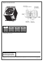
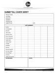
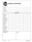
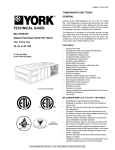
SUBMITTAL COVER SHEET
PROJECT NAME
LOCATION
ARCHITECT
ENGINEER
CONTRACTOR
SUBMITTED BY
DATE
UNIT SUMMARY
Quantity
Unit Designation
Model No.
Total Cooling
Sensible Cooling
Air Ent. Evaporator
Air Lvg. Evaporator
Heating Input
Heating Output
CFM/ESP
EER/SEER
Electrical
Minimum Ampacity
Min.-Max. Breaker
Net Unit Weight
Accessory
Catalog Form Number
ACCESSORIES:
NOTES:
PRINTED IN U.S.A 01/12 QG FORM NO. M11-1640
FORM NO. X33-1407
Supersedes Form No. X66-1317 Rev. 1
13A(-)N SERIES AIR CONDITIONER
EFFICIENCIES UP TO 14.5 SEER/12 EER
NOMINAL SIZES 1.5 TO 5 TONS [5.28 TO 17.6 kW]
JOB NAME
LOCATION
CONTRACTOR
ORDER NO.
ENGINEER
UNIT MODEL NO.
SUBMITTED FOR
APPROVAL
RECORD
DATE
COIL MODEL NO.
AIR HANDLER MODEL NO.
UNIT DATA
COOLING PERFORMANCE
FEATURES FOR 13A(-)N SERIES
AIR CONDITIONERS
1.5 TO 5 NOMINAL TON [5.28 TO 17.6 kW]
EFFICIENCY .................................. _______ SEER
TOTAL CAPACITY*.................... _______ MBH [kW]
SENSIBLE CAPACITY* .............. _______ MBH [kW]
OUTDOOR DESIGN TEMP. ........ _______ °F [°C] DB
■
TEMP. OF AIR ENTERING
EVAPORATOR COIL .............. _______ °F [°C] DB
■
■
_______ °F [°C] WB
POWER INPUT REQUIREMENT .......... _______ kW
(*uses blower motor heat)
■
■
Painted louvered steel cabinet
Easily accessible control box
Condenser coils constructed with copper tubing and enhanced
aluminum fins
Grille/Motor mount for quiet fan operation
Filter Drier (shipped – not installed)
SUPPLY AIR BLOWER PERFORMANCE
ACCESSORIES
TOTAL AIR SUPPLY .................. _______ CFM [L/s]
TOTAL RESISTANCE EXTERNAL
TO UNIT........................................ _______ IWG
BLOWER SPEED.............................. _______ RPM
POWER OUTPUT REQUIREMENT .... _______ BHP
MOTOR RATING .......................... _______ HP [W]
POWER INPUT REQUIREMENT .......... _______ kW
Low Pressure Control....................................................
High Pressure Control ........................................................
Low Ambient Control ..........................................................
Compressor Time Delay Control ........................................
Crankcase Heater ........................................................
Sound Enclosure ................................................................
ELECTRICAL DATA
POWER SUPPLY .......................... ___________Hz
TOTAL UNIT AMPACITY.................. _______ AMPS
MINIMUM WIRE SIZE ...................... _______ AWG
MAXIMUM OVERCURRENT DEVICE
FUSES/HACR BREAKER ............ _______ AMPS
16.0
CLEARANCES
ACCESS SIDE
24" [609.6 mm]
AIR INLETS
6" [152.4 mm]
ABOVE UNIT
60" [1524 mm]
“Proper sizing and installation of equipment is critical to achieve optimal performance.
Ask your Contractor for details or visit www.energystar.gov.”
13A(-)N 18, 24, 30, 36, 42, 48, 60
w
L
H
SEE DETAIL A
Model No.
13A(-)N
18, 24
30, 36, 42
48
60
Unit Dimensions
Width “W”
Inches
Length “L”
Inches
Height “H”
Inches
235/8 [600]
275/8 [702]
315/8 [803]
315/8 [803]
235/8 [600]
275/8 [702]
315/8 [803]
315/8 [803]
241/4 [616]
241/4 [616]
2715/16 [710]
3515/16 [913]
[ ] Designates Metric Conversions
Before proceeding with installation, refer
to installation instructions packaged
with each model, as well as complying
with all Federal, State, Provincial, and
Local codes, regulations, and practices.
“In keeping with its policy of continuous progress and product improvement, Manufacturer reserves the right to make changes without notice.”
PRINTED IN U.S.A.
11-12 QG
FORM NO. X33-1407
Supersedes Form No. X66-1317 Rev. 1