1
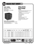
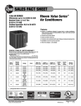
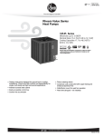
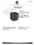
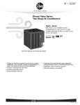
SUBMITTAL COVER SHEET
PROJECT NAME ______________________________________________________________________________
LOCATION __________________________________________________________________________________
ARCHITECT__________________________________________________________________________________
ENGINEER __________________________________________________________________________________
CONTRACTOR ______________________________________________________________________________
SUBMITTED BY
______________________________ DATE ________________________________________
UNIT SUMMARY
Quantity
Unit Designation
Model No.
Total Cooling
Sensible Cooling
Air Ent. Evaporator
Air Lvg. Evaporator
Heating Input
Heating Output
CFM/ESP
EER/SEER
Electrical
Minimum Ampacity
Min.-Max. Breaker
Net Unit Weight
Accessory
Catalog Form Number
ACCESSORIES:
PRINTED IN U.S.A.
NOTES:
10-06 DC
FORM NO. X11-1123 REV. 2
Supersedes Form No. X11-1123 Rev. 1
FORM NO. X66-1298 REV. 1
Supersedes Form No. X66-1298
SUBMITTAL SHEET FOR 15PJL SERIES
11/2 TO 5 NOMINAL TON [5.28 TO 17.58 kW], 15 SEER
HEAT PUMP UNITS
Featuring Industry
Standard R-410A
Refrigerant
JOB NAME
LOCATION
CONTRACTOR
ORDER NO.
ENGINEER
UNIT MODEL NO.
SUBMITTED FOR
APPROVAL
RECORD COIL MODEL NO.
DATE
AIR HANDLER MODEL NO.
FEATURES FOR 15PJL SERIES HEAT PUMP UNITS
11/2 TO 5 NOMINAL TON [5.28 TO 17.58 kW]
UNIT DATA
COOLING PERFORMANCE
EFFICIENCY ................................ _______ SEER
TOTAL CAPACITY*.................. _______ MBH [kW]
SENSIBLE CAPACITY*............ _______ MBH [kW]
OUTDOOR DESIGN TEMP. .... _______ °F [°C] DB
TEMP. OF AIR ENTERING
EVAPORATOR COIL............ _______ °F [°C] DB
■
■
■
■
■
■
■
_______ °F [°C] WB
■
POWER INPUT REQUIREMENT ........ _______ kW
■
(*uses blower motor heat)
■
■
HEATING PERFORMANCE
■
■
EFFICIENCY ................................ _______ HSPF
■
TOTAL CAPACITY*.................. _______ MBH [kW]
ACCESSORIES/OPTIONS
OUTDOOR DESIGN TEMP. .... _______ °F [°C] DB
TEMP. OF AIR ENTERING
EVAPORATOR COIL............ _______ °F [°C] DB
SUPPLY AIR BLOWER PERFORMANCE
TOTAL RESISTANCE EXTERNAL
TO UNIT...................................... _______ IWG
BLOWER SPEED .......................... _______ RPM
Optional High Pressure Control (Model No. RXAB-A07)
■
Heat Pump Thermostat Warning Light Kit
(Model No. RXPX-D01) ........................................................
Low Ambient Control (Model No. RXAD-A08) ..............................
Outdoor Thermostats (Model No. RXPT-A01, A02, A03 or A04) ......
Heat Pump Monitor (Model No. RXPM-B01) ..............................
Thermostats and Subbases (Available through the
PROSTOCK® department) ......................................................
Compressor Time Delay Control (Model No. RXMD-B01) ..............
Blower Time Delay Control (Model No. RXMD-C04) RXMD-C04 is
not required if the outdoor unit is matched with a furnace or air
handler from the Manufacturer, or if the furnace or air handler used
has a blower off time delay built-in. ..........................................
Sound Enclosure* ................................................................
Start Components* ..............................................................
■
■
■
■
■
POWER OUTPUT REQUIREMENT .. _______ BHP
MOTOR RATING ........................ _______ HP [W]
POWER INPUT REQUIREMENT ........ _______ kW
ELECTRICAL DATA
................
■
■
TOTAL AIR SUPPLY ................ _______ CFM [L/s]
35" Maximum Unit Height.
Coils constructed with copper tubing and enhanced aluminum fins.
Strong, attractive cabinet—louvered design protects the coil from
damage.
Expansion Valves with Internal Check Valve—Provides for quieter
refrigerant metering.
Enhanced Demand Defrost Control
Factory Installed Low Pressure Control
Non-Cycling Reversing Valve
Hot Gas Muffler
Service Valves
Grille/motor mount for quiet fan operation.
Easily accessible control box.
Bi-Directional Filter Drier (Field Installed)
Certified and rated under A.H.R.I. Standard 240.
U.L listed.
■
■
*Available through the PROSTOCK® department.
POWER SUPPLY ......................____________ Hz
TOTAL UNIT AMPACITY................ _______ AMPS
MINIMUM WIRE SIZE .................... _______ AWG
MAXIMUM OVERCURRENT DEVICE
FUSES/HACR BREAKER .......... _______ AMPS
CLEARANCES
ACCESS SIDE
24" [609.6 mm]
AIR INLETS
12" [304.8 mm]
ABOVE UNIT
60" [1524 mm]
(IN CERTAIN MATCHED SYSTEMS)
15PJL 18, 24, 30,
36, 42, 48, 60
w
L
H
SEE DETAIL A
Model No.
15PJL
18, 24
30
36, 42, 48, 60
Height “H”
Inches [mm]
Unit Dimensions
Length “L”
Inches [mm]
Width “W”
Inches [mm]
261/4 [666.75]
275/8 [702]
275/8 [702]
273/8
315/8
[803]
315/8 [803]
315/8 [803]
315/8 [803]
[695.32]
353/8 [898.52]
[ ] Designates Metric Conversions
NOTES:
Before proceeding with installation, refer
to installation instructions packaged
with each model, as well as complying
with all Federal, State, Provincial, and
Local codes, regulations, and practices.
“In keeping with its policy of continuous progress and product improvement, Manufacturer reserves the right to make changes without notice.”
PRINTED IN U.S.A.
1-11 DC
FORM NO. X66-1298 REV. 1
Supersedes Form No. X66-1298