1
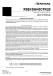
R0E436049CFJ10
Converter Board for 80-pin 0.65-mm-pitch QFP for H8/36049 Group
User’s Manual
* IC149-080-017-B5 is a trademark of Yamaichi Electronics Co., Ltd.
Keep safety first in your circuit designs!
Renesas Technology Corporation and Renesas Solutions Corporation put the maximum effort into making semiconductor products
better and more reliable, but there is always the possibility that trouble may occur with them. Trouble with semiconductors may lead to
personal injury, fire or property damage. Remember to give due consideration to safety when making your circuit designs, with
appropriate measures such as (i) placement of substitutive, auxiliary circuits, (ii) use of nonflammable material or (iii) prevention
against any malfunction or mishap.
Notes regarding these materials
These materials are intended as a reference to assist our customers in the selection of the Renesas Technology product best suited
to the customer's application; they do not convey any license under any intellectual property rights, or any other rights, belonging to
Renesas Technology Corporation, Renesas Solutions Corporation or a third party.
Renesas Technology Corporation and Renesas Solutions Corporation assume no responsibility for any damage, or infringement of
any third-party's rights, originating in the use of any product data, diagrams, charts, programs, algorithms, or circuit application
examples contained in these materials.
All information contained in these materials, including product data, diagrams, charts, programs and algorithms represents information
on products at the time of publication of these materials, and are subject to change by Renesas Technology Corporation and
Renesas Solutions Corporation without notice due to product improvements or other reasons. It is therefore recommended that
customers contact Renesas Technology Corporation, Renesas Solutions Corporation or an authorized Renesas Technology product
distributor for the latest product information before purchasing a product listed herein. The information described here may contain
technical inaccuracies or typographical errors. Renesas Technology Corporation and Renesas Solutions Corporation assume no
responsibility for any damage, liability, or other loss rising from these inaccuracies or errors. Please also pay attention to information
published by Renesas Technology Corporation and Renesas Solutions Corporation by various means, including the Renesas home
page (http://www.renesas.com).
When using any or all of the information contained in these materials, including product data, diagrams, charts, programs, and
algorithms, please be sure to evaluate all information as a total system before making a final decision on the applicability of the
information and products. Renesas Technology Corporation and Renesas Solutions Corporation assume no responsibility for any
damage, liability or other loss resulting from the information contained herein.
Renesas Technology semiconductors are not designed or manufactured for use in a device or system that is used under
circumstances in which human life is potentially at stake. Please contact Renesas Technology Corporation, Renesas Solutions
Corporation or an authorized Renesas Technology product distributor when considering the use of a product contained herein for any
specific purposes, such as apparatus or systems for transportation, vehicular, medical, aerospace, nuclear, or undersea repeater use.
The prior written approval of Renesas Technology Corporation and Renesas Solutions Corporation is necessary to reprint or
reproduce in whole or in part these materials.
If these products or technologies are subject to the Japanese export control restrictions, they must be exported under a license from
the Japanese government and cannot be imported into a country other than the approved destination. Any diversion or reexport
contrary to the export control laws and regulations of Japan and/or the country of destination is prohibited.
Please contact Renesas Technology Corporation or Renesas Solutions Corporation for further details on these materials or the
products contained therein.
Precautions to be taken when using this product
This product is a development supporting unit for use in your program development and evaluation stages. In mass-producing your
program you have finished developing, be sure to make a judgment on your own risk that it can be put to practical use by performing
integration test, evaluation, or some experiment else.
In no event shall Renesas Solutions Corporation be liable for any consequence arising from the use of this product.
Renesas Solutions Corporation strives to renovate or provide a workaround for product malfunction at some charge or without charge.
However, this does not necessarily mean that Renesas Solutions Corporation guarantees the renovation or the provision under any
circumstances.
This product has been developed by assuming its use for program development and evaluation in laboratories. Therefore, it does not
fall under the application of Electrical Appliance and Material Safety Law and protection against electromagnetic interference when
used in Japan.
CAUTION
Renesas Tools Homepage
Rev.2.00
Feb. 02, 2006
REJ10J1175-0200
If the requirements shown in the "CAUTION" sentences are ignored,
the equipment may cause personal injury or damage to the products.
http://www.renesas.com/en/tools
(1/6)
1. Outline
The R0E436049CFJ10 is a converter board for connecting the
compact emulator R0E436640CPE00 for H8/300H Tiny Series
to a foot pattern for 80-pin 0.65-mm-pitch QFP
(PRQP0080JB-A) of H8/36049 Group.
2. Package Components (See Figure 1)
Item
(1) R0E436049CFJ10
(150mm FFC cable and Base board
R0E436049EPBS0 included)
(2) IC149-080-017-B5
(made by Yamaichi Electronics Co., Ltd)
Screws (M2 x 12mm)
Flat washers
(for fixing the converter board)
IC socket
Socket cover
Screws (M2 x 8mm)
Flat washers (for on-board evaluation)
(3) R0E436049CFJ10 User's Manual
(This manual)
Quantity
R0E436049CFJ10
(150mm FFC cable and
base board R0E436049EPBS0 included)
1 pc.
1 pkg.
IC socket
4 pcs.
4 pcs.
Socket cover
1 pc.
1 pc.
4 pcs.
4 pcs.
Screws (M2x12mm)
Flat washers (for fixing converter board)
Screws (M2x8mm)
Flat washers (for on-board evaluation)
Figure 1 Package components of the R0E436049CFJ10
1 pc.
3. Specifications
Table 1 Specifications
Applicable group
Applicable package
Insertion/removal
iterations of
connector
H8/36049 Group
PRQP0080JB-A
*Previous Code FP-80A
(80-pin 0.65-mm-pitch QFP)
Between R0E436640CPE00 and
R0E436049CFJ10:
50 times guaranteed
4. Usage (See Figure 2)
(1) Debugging
The R0E436049CFJ10 can be used for debugging and board
mounted evaluation in common by mounting an IC socket on
the user system.
R0E436640CPE00
Screws (M2x12mm) *
R0E436049CFJ10
Flat washers *
(1) For debugging
Mount the IC socket on the foot pattern of the user system
in that order.
After
connecting
the
R0E436640CPE00
and
R0E436049EPBS0, connect the R0E436049CFJ10 to the
IC socket. And fix them with the screws (M2 x 12mm)
included with the R0E436049CFJ10.
Even if the H8/36049 Group MCU is emulated without
connecting to the user system, the R0E436049CFJ10
needs to be connected to the R0E436640CPE00.
(2) On-board evaluation
Screws (M2x8mm) *
R0E436049EPBS0
Socket cover *
Flat washers *
MCU with on-chip
flash memory etc.
IC Socket *
80-pin 0.65-mm-pitch
( PRQP0080JB-A ) foot pattern
●: No.1 pin
*: These products are included with the R0E436049CFJ10 package.
(2) For onboard evaluation
Mount an H8/300H Tiny Series MCU in that order on the
IC socket on the user system. And fix them with the
screws (M2 x 8mm) included with the R0E436049CFJ10.
Before using the R0E436049CFJ10, be sure to read "7.
Precautions" on page 4 and the R0E436640CPE00 User’s
Manual.
Figure 2 Usage of the R0E436049CFJ10
(2/6)
5. Connection Procedure (See Figure 3)
The procedure for connecting the R0E436049CFJ10 is shown
below.
(1) Mount the IC socket on the user system.
(2) Connect the R0E436640CPE00 and R0E436049EPBS0.
(3) Connect the R0E436049CFJ10 and IC socket.
Fasten the IC socket to the socket cover with the four
screws (M2 x 12 mm) provided. Each screw should be
tightened a little at a time, alternating between screws on
opposing corners. Take special care, such as manually
securing the IC socket soldered area, to prevent the
soldered IC socket from being damaged by overtightening
the screws or twisting the components.
R0E436640CPE00
Screws (M2x12mm) *
(2)
Flat washers*
(4) R0E436049CFJ10
R0E436049EPBS0
(3)
IC socket *
(1)
80-pin 0.65-mm-pitch
(PRQP0080JB-A) foot pattern
● When connecting the IC socket and socket cover, use
a Phillips-type screwdriver whose head matches the
screw head.
● If the applied torque cannot be accurately measured,
stop tightening when the force required to turn the
screw becomes significantly greater than that needed
when first tightening (The tightening torque must be
0.0785 N•m or less). If a screw is tightened too much,
the screw head may break or an IC socket contact
error may be caused by a crack in the IC socket
solder.
● If the emulator does not operate correctly, cracks
might have occurred in the solder. Check conduction
with a tester and re-solder the IC socket if necessary.
Figure 3 Connection procedure of the R0E436049CFJ10
6. External Dimensions and a Recommended Foot Pattern (See Figure 4)
Note that the dimensions of the recommended foot pattern in Figure 4 are somewhat different from those of the actual foot pattern.
50.0
14.70 max
20.50 min
+0.10
-0.05
45.0
0.35
R0E436049CFJ10 REV.A
MADE IN JAPAN
14.0
0.65±0.05
14.70 max
20.50 min
Unit: mm
Figure 4 External dimensions and a recommended foot pattern of the R0E436049CFJ10
(3/6)
7. Precautions
7.1 Restriction for Using the Emulator
(1) Precautions for the register access
Please take notice the following precautions for register access because there are differences between the product chip and an
evaluation chip.
The description given in the hardware manual is “Initial value: 0. Reserved. These bits are always read as 0”. However, the
description in the evaluation chip is “Always specify 0. These bits are always read as the specify values”.
Target address and bit:
Bits 7, 6 and 5 of address H’FFFFE2 (Port mode register 3)
Bits 7 and 6 of address H’FFFFF5 (Interrupt enable register 2)
Bit 7 of address H’FFFFF9 (Module standby control register 1)
Bits 6, 5 and 3 of address H’FFFFFA (Module standby control register 2)
The description in the hardware manual is “Reserved”. However, the description in the evaluation chip is “Always specify 0. These
bits are always read as the specified values”.
Target address and bit:
Bit 0 of address H’FFFFFB
The hardware manual shows registers at the addresses given below. For these locations, however, the applicable description in the
evaluation chip is “Writing has no effect. These bits are always read as undefined values”, because there are no registers at these
locations of the evaluation chip.
Target address:
H’FFF730 (Low-voltage-detection control register)
H’FFF731 (Low-voltage-detection status register)
H’FFFF90 (Flash memory control register 1)
H’FFFF91 (Flash memory control register 2)
H’FFFF92 (Flash memory power control register)
H’FFFF93 (Erase block register 1)
H’FFFF9B (Flash memory enable register)
(2) Note on Power-on Reset and Low-voltage Detection Circuit Functions
The product chip has optional functions of power-on reset and low-voltage detection circuit and can select them. However, since
the evaluation chip does not support these functions, software debugging cannot be performed in the emulator. Be sure to
evaluate your system and make final confirmation with a product chip.
(3) Note on Serial Interface SCI3_3
Because the evaluation chip does not incorporate the SCI3_3 module, it emulates the SCI3_3 function by connecting an external
circuit on the R0E436049CFJ10. When using the SCI3_3, be sure to set the multiplexed port control registers (PCR: P90, P91
and P92) to “0” (input) beforehand. If using emulators, set the bit 3 of the address H’FFF608 (Serial mode control register3) to
“1”.
R0E436640CPE00
EVACHIP
P12,P56,P57
R0E436049CFJ10
Level
FPGA converver
22Ω
P90,P91,P92
User
System
Analog SW
Others
Figure 5 Connections of the R0E436049CFJ10
(4/6)
47Ω
Table 2 Differences between the emulator and H8/36049 registers
Address Registers
Bit 7
Bit 6
Bit 5
Bit 4
Bit 3
H'F608 ("1")*1
H'F730 H'F731 H'FF90 H'FF91 H'FF92 H'FF93 H'FF9B Emulator
H'FFE0 PMR1
IRQ3
IRQ2
IRQ1
IRQ0
TXD2
H'FFE1 PMR5
POF57
POF56
WKP5
WKP4
WKP3
H'FFE2 PMR3
POF27
POF26
POF25
POF24
POF23
H'FFF1 SYSCR2
SMSEL
LSON
DTON
MA2
MA1
H'FFF2 IEGR1
NMIEG
IEG3
H'FFF4 IENR1
IENDT
IENTA
IENWP
IEN3
H'FFF5 IENR2
IENTB3
IENTB2 IENTB1 H'FFF9 MSTCR1
MSTS4
MSTIIC
MSTS3
MSTAD MSTWD
H'FFFA MSTCR2
MSTS3_2 MSTTB3 MSTTB2 MSTTB1 MSTTX
H'FFFB MSTCR3
*1 If using emulators, set the bit 3 of the address H’FFF608 (Serial mode control register) to “1”.
Bit 2
NFEN_3
PWM
WKP2
MA0
IEG2
IEN2
MSTTW
-
Bit 1
TXD_3
TXD
WKP1
SA1
IEG1
IEN1
MSTTV
MSTTZ
-
Bit 0
MSTS3_3
TMOW
WKP0
SA0
IEG0
IEN0
MSTTA
MSTPWM
MSTS4_2
Address Registers
Bit 7
H'F608 H'F730 LVDCR
LVDE
H'F731 LVDSR
H'FF90 FLMCR1
H'FF91 FLMCR2
FLER
H'FF92 FLPWCR
PDWND
H'FF93 EBR1
EB7
H'FF9B FENR
FLSHE
H8/36049
H'FFE0 PMR1
IRQ3
H'FFE1 PMR5
POF57
H'FFE2 PMR3
H'FFF1 SYSCR2
SMSEL
H'FFF2 IEGR1
NMIEG
H'FFF4 IENR1
IENDT
H'FFF5 IENR2
H'FFF9 MSTCR1
H'FFFA MSTCR2
MSTS3_2
H'FFFB Note: The thick boxes indicate differences
Bit 2
NFEN_3
LVDRE
PV
EB2
PWM
WKP2
MA0
IEG2
IEN2
MSTTW
-
Bit 1
TXD_3
LVDDE
LVDDF
E
EB1
TXD
WKP1
SA1
IEG1
IEN1
MSTTV
MSTTZ
-
Bit 0
MSTS3_3
LVDUE
LVDUF
P
EB0
TMOW
WKP0
SA0
IEG0
IEN0
MSTTA
MSTPWM
-
Bit 6
SWE
EB6
IRQ2
POF56
LSON
IENTA
MSTIIC
-
Bit 5
ESU
EB5
IRQ1
WKP5
DTON
IENWP
IENTB1
MSTS3
-
(5/6)
Bit 4
PSU
EB4
IRQ0
WKP4
POF24
MA2
MSTAD
MSTTB1
-
Bit 3
LVDSEL
EV
EB3
TXD2
WKP3
POF23
MA1
IEG3
IEN3
MSTWD
-
7.2 Notes on Using the Product
CAUTION
Cautions to Be Taken for This Product:
Do not connect anything to the NC pins.
Do not pull or excessively flex the cable. The cable may cause a break.
When connecting the emulator and IC socket, be sure to use the included screws (M2 x 12mm).
When connecting the IC socket and socket cover, be sure to use the included screws (M2 x 8mm).
When connecting the IC socket and socket cover, use a Phillips-type screwdriver whose head matches the screw
head.
If the applied torque cannot be accurately measured, stop tightening when the force required to turn the screw
becomes significantly greater than that needed when first tightening (The tightening torque must be 0.0785 N•m or
less). If a screw is tightened too much, the screw head may break or an IC socket contact error may be caused by a
crack in the IC socket solder.
If the emulator does not operate correctly, cracks might have occurred in the solder. Check conduction with a tester
and re-solder the IC socket if necessary.
Fasten the IC socket to the socket cover with the four screws (M2 x 8 mm, with flat washers) provided. Each screw
should be tightened a little at a time, alternating between screws on opposing corners. Take special care, such as
manually securing the IC socket soldered area, to prevent the soldered IC socket from being damaged by
overtightening the screws or twisting the components.
After checking the location of pin 1 on the IC socket, apply epoxy resin adhesive to the bottom of the IC socket, and
fasten it to the user system before soldering.
Be sure to completely solder the leads so that the solder slops gently over the leads and forms solder fillets. (Use
slightly more solder than the MCU.)
IMPORTANT
Notes on This Product:
We cannot accept any request for repair.
For purchasing the IC149-080-017-B5, contact the following:
Yamaichi Electronics Co., Ltd.
http://www.yamaichi.com/
For inquiries about the product or the contents of this manual, contact your local distributor.
Renesas Tools Homepage
http://www.renesas.com/en/tools
7.3 How to add the MCU and IO File
If there is no “h836049.mcu” in the file selection dialog box of the emulator debugger, it is necessary to add the information specific
to the H8/36049 group MCU. Add the MCU and IO files following the procedure below.
(1) Please download the MCU and IO files installer from the web site below.
http://tool-support.renesas.com/eng/toolnews/n060216/download.htm
Files to be downloaded:
MCUIO_Files_install_cpe_h8tiny_060202.exe
(2) Execute the downloaded installer to add the MCU and IO files to the emulator debugger.
(6/6)