1
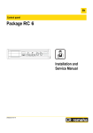
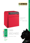
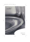
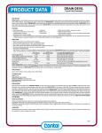
REMEHA PRESSURE JET RANGE
P Series
Pressure Jet Range
Gas, Oil and Dual fuel pressure
jet three-pass cast iron sectional
boiler with low NOx emissions
PRESSURE JET OUTPUTS
P 320: 70-330 kW
P 420: 300-780 kW
P 520: 696-1450 kW
Introduction
Boiler Description
The Remeha P Series Range
is a family of advanced
technology boilers, giving
value for money when used
on both commercial and
industrial applications.
All the models are suitable
for gas, oil, dual fuel and
bio-fuel. They are compact
in size yet designed to be
extremely powerful, meeting
all requirements on both
full and part load giving
high operating efficiency
and low emissions.
The Remeha Pressure Jet Range are high efficiency
pressurised hot water boilers suitable for use with natural
gas, light oil and bio fuel, by means of a pressure jet burner.
Nominal output of the P 320 boilers is between 70 and
330 kW, the P 420 boilers is between 300 and 780 kW and
the P 520 boilers is between 754 and 1450 kW.
The main boiler casing is steel, with a powder coated
enamel finish complete with high quality 80-100mm thick
glass wool insulation. The front door is suitable for left or
right opening allowing easy access for service operations.
The heat exchanger is manufactured from corrosionresistant ‘Eutectic’ cast iron.
The instrument panel contains all the necessary control and
measuring instruments required to control the boiler with
the external connections on a terminal strip. The capillaries
and sensor wires of the control panel are placed in the
instrument pockets fitted at the front of the boiler.
For the discharge of flue gases, chimney draught is not
required. Tests have shown that very good combustion
results are obtained with zero draught at the boiler outlet.
The boilers are suitable for open and sealed systems up to
a maximum pressure of 6 bar and a minimum pressure of
0.8 bar. The boiler is suitable for installation in basement
or rooftop plant rooms.
The sizes of boilers parts are such that they can enter the
plant room through a normal entrance. The casing and
instrument panel are packed separately.
The boiler block consists of cast iron sections which are
assembled by means of tapered nipples and ceramic rope.
The boilers are designed on the basis of the triple
pass principle for maximum efficiency and a generously
sized combustion chamber for minimising NOx production.
Contents
2
page
Introduction
2
Boiler Description
2
Typical Boiler Construction
3
Advantages at a Glance
3
P 320 Dimensions
& Technical Data
4-5
P 420 Dimensions
& Technical Data
6-7
P 520 Dimensions
& Technical Data
8-9
Application Information
10
Instrument Panels
10
External Connections
10
Water Treatment
11
In principle, all EC approved pressure jet burners are
suitable subject to boiler capacity and construction.
The boilers meet the requirements of the EC regulations in
the following directives:
-
-
-
-
-
97/23/Sound engineering (article 3.3)
90/396/Gas appliance directive
73/23/Electrical low voltage directive
89/336/E.M.C. directive
92/42/Efficiency directive
Classification type for evacuation of the combustion
products: B23.
Advantages
at a glance
Typical Boiler Construction
Remeha P 320
7
8
• Boiler body with 3-pass flueways
design with a large combustion
chamber and horizontal flue
passes with fins. The heat
transfer is enhanced by the
fins and the cast iron baffles
1
2
• A high combustion efficiency
3
6
• A low noise level operation
5
• Optimal combustion with low
NOx and CO2 emissions
4
• Easy adaptation to traditional
burners, as well as new burners
with low NOx emissions
Remeha P 420
7
8
• Hinged burner / cleaning door
(right hand side or left hand side)
1
2
3
6
• Eutectic cast iron boiler body
provides exceptional resistance
to temperature variations,
thermal shocks and corrosion
• Safe low modulated temperature
operation down to 40°C
5
• Reinforced fibreglass wool
insulation (100 mm) and double
insulation of the boiler front
which minimises heat loss
and allows reduced stand-by
consumption and improved
thermal efficiency
4
Remeha P 520
7
• Internal electrical duct for
wiring connections
1
• Easy installation for existing or
new boiler houses
2
6
3
5
8
4
• The assembly of the sectional
boiler body can be carried out
anywhere even in boiler houses
with difficult access
• A maximum working pressure
of 6 bar allows for most types
of installation
• Volt free wiring connections
for external run and lock-out
indication
1 Boiler body with pass flue ways
6 Flame observation window
2 Large-sized combustion chamber
7Control panel designed to enable easy
wiring connections
3 Complete insulated boiler body
with fibreglass wool, 100 mm thick
4 Ceramic fibre insulated burner door
5 Hinged burner door fitted
(right hand side or left hand side)
8 Eutectic cast iron body, thermal shock
and corrosion resistant, allowing low
modulated temperature operation and
complete stop between two heating periods
3
Remeha P 320
Dimensions
All measurements in mm
Front View
Side View
Rear View
Dimensions of the Sections
Remeha P 320
Number of sections
L (mm)
P (mm)
ØR (mm)
Flow and Return connection sizes
4
4
5
6
7
8
9
991
490
180
2.5”
1151
650
180
2.5”
1311
810
180
2.5”
1471
970
200
2.5”
1631
1130
200
2.5”
1791
1290
200
2.5”
Maximum operating pressure: 6 bar. Boiler thermostat setting: 20 to 90 ºC. Safety thermostat setting: 110 ºC.
Remeha P 320
Number of Sections
Nominal output
Nominal input
Efficiency 100% load (NCV)
Seasonal efficiency (GCV)
Water contents
Water resistance
T=11°C (1)
T=15°C (1)
T=20°C (1)
Pressure in the furnace for
nozzle pressure = 0
Flue gas temperature(1)(3)
Mass flue gas flow rate(1)(2)
Gas
Combustion chamber diameter
Standing losses
T=50c
Shipping Weight
4
5
6
7
8
9
kW
kW
%
%
Iitre
mbar
mbar
mbar
70-105
76-117
88
83.4
96
11.54
6.2
3.47
105-140
115-156
88
83.6
116
20.3
10.9
6.11
140-180
153-199
88
83.6
136
37.8
20.4
11.45
180-230
197-253
88
84
156
56
30
16.94
230-280 252-309
88
84.2
176
82.5
44.5
24.96
280-330
305-361
88
84.2
196
119
63.8
35.93
mbar
+0.3
+0.6
+1.1
+1.6
+2.2
+2.5
°C
Kg/h
mm
%
kg
<210
187
377
0.17
636
<210
250
377
0.14
755
<210
321
377
0.13
907
<210
410
377
0.11
1037
<210
499
377
0.10
1169
<210
588
377
0.09
1304
Nominal operation (Top boiler power)
CO2 = 13.1 to 13% with fuel oil and 9.5% with natural gas
(3) Boiler temperature 80°C
(1)
(2)
Minimum Boiler Base Dimensions
Remeha P 320
REMEHA PRESSURE JET RANGE
Technical Data
Remeha P 320
Number of sections
4
5
6
7
8
9
L (mm)
838
998
1158
1318
1478
1638
C min = 1.5 mtrs min and max dependent on make and model of burner
The Remeha P 320 boilers do not require a special base for their assembly. Their
closed furnace system means that the floor need not have refractory properties.
Ensure that the floor can support the weight of the boiler when it is fitted for operation.
If the boiler location is not determined precisely, leave enough space around the boiler
to facilitate monitoring and maintenance operations.
5
Remeha P 420
Dimensions
All measurements in mm
Front View
Side View
Rear View
Dimensions of the Sections
Remeha P 420
Number of sections
8
9
10
11
12
13
ØA (mm)
250
250
250
300
300
300
ØB (mm)
2.5”
2.5”
2.5”
3”
3”
3”
∆ T=10ºC(1)
ØC (mm)
Plate intact or pre-drilled to the diameter specified on order
∆ T=15ºC(1)
D (mm)
235
235
235
254
254
254
∆ T=20ºC(1)
E (mm)
1427
1427
1427
1447
1447
1447
J (mm)
1800
1950
2120
2305
2465
2625
L (mm)
1505
1665
1825
1985
2145
2305
S (mm)
1183
1343
1503
1663
1823
1983
6
14
300
3”
254
1447
2785
2465
2143
Maximum operating pressure: 6 bar. Boiler thermostat setting: 30 to 90 ºC. Safety thermostat setting: 110 ºC.
Remeha P 420
Number of Sections
Nominal output
Nominal input
Efficiency 100% load (NCV)
Seasonal efficiency (GCV) (Avg) Water contents
Water resistance
T=11°C (1)
T=15°C (1)
T=20°C (1)
Pressure in the furnace for
nozzle pressure = 0(1)(3)(2)
Flue gas temperature(1)(3)
Mass flue gas flow rate(1)(2)
Gas
Combustion chamber diameter
Maintenance consumption @50c
Shipping Weight
8
9
10
11
12
13
14
kW 300-390 390-450 450-540 540-600 600-670 670-720 720-780
kW 329-434 429-502 495-599 594-670 661-751 737-804 789-871
%
88
88
88
88
88
88
88
%
82.2
82.2
82.2
82.2
82.2
82.2
82.2
Iitre
366
409
452
495
538
581
624
mbar
31.4
59.35
74.35
89.13
110.77
132.17 178.69
mbar
14
21
36
45
58
70
87
mbar
8
12
20
25
33
40
49
mbar
+1.1
+1.5
+2.0
+2.5
+2.5
+2.5
+3.5
°C
Kg/h
mm
W
kg
<220
700
530
315
1978
<220
810
530
358
2194
<220
972
530
413
2399
<220
1080
530
451
2653
<220
1207
530
494
2836
<220
1297
530
505
3070
<220
1405
530
555
3296
Nominal operation (Top boiler power)
CO2 = 13.1 to 13% with fuel oil and 9.5% with natural gas
(3) Boiler temperature 80°C
(1)
(2)
Minimum Boiler Base Dimensions
Remeha P 420
REMEHA PRESSURE JET RANGE
Technical Data
Remeha P 420
Number of sections
L (mm)
8
9
10
11
12
13
14
1505
1665
1825
1985
2145
2305
2465
C min = 1.5 mtrs min and max dependent on make and model of burner
The Remeha P 420 boilers do not require a special base for their assembly. Their
closed furnace system means that the floor need not have refractory properties.
Ensure that the floor can support the weight of the boiler when it is fitted for operation.
If the boiler location is not determined precisely, leave enough space around the boiler
to facilitate monitoring and maintenance operations.
7
Remeha P 520
Dimensions
All measurements in mm
Front View
Side View
Dimensions of the Sections
Remeha P 520
Number of sections
A (mm)
B (mm)
C (mm)
D (mm)
ØE (weld) (mm)
ØF (mm)
G (mm)
H (mm)
K** (mm)
L (mm)
M (mm)
P (mm)
R (mm)
S (mm)
T (mm)
U (mm)
13
1563
1522
∆ T=10ºC(1)
1488
∆ T=15ºC(1)
256
∆ T=20ºC(1)
139.7
350
-
37
49
1955
275
355
175
1760
1372
2021.5
15
17
19
21
23
25
1785
1744
1488
188
139.7
400
150
-31
-19
2245
324
355
175
1760
1594
2243.5
2007
1966
1488
210
139.7
400
370
-9
3
2445
321
355
175
1760
1816
2465.5
2229
2188
1504
257
159
400
370
13
25
2645
299
355
175
1760
2038
2687.5
2491
2450
1504
209
159
*
650
-35
-23
2955
324
355
175
1760
2300
2949.5
2713
2672
1504
231
159
*
980
-13
-1
3155
324
355
175
1760
2522
3171.5
2935
2894
1504
253
159
*
980
9
21
3355
303
355
175
1760
2744
3393.5
* Plain plate, requires cutting. Maximum cut-out 500 x 700
** Dimension representing the end of the 100 mm long chimney connection
G = Length required for clearing the water distributing tube
Note: with models P 520-21, P 520-23 and P 520-25, a plain plate which must be cut out
is supplied without the 100 mm chimney connection
8
Maximum operating pressure: 6 bar. Boiler thermostat setting: 30 to 90 ºC. Safety thermostat setting: 110 ºC.
Remeha P 520
Number of Sections
Nominal output
Nominal input
Efficiency 100% load (NCV)(3)
Seasonal Efficiency (GCV)
Water capacity
Water resistance
T=11°C T=15°C T=20°C Pressure in the furnace for
nozzle pressure = 0
Flue gas temperature(1)(3)
Mass flue gas flow rate(1)(2) Fuel oil
Gas
Maintenance consumption T=30k
Shipping Weight
13
15
17
19
21
23
25
kW 696-754 812-870 928-986 1044-11021160-1218 1276-13341400-1450
kW 763-831 897-967 1022-1093 1146-12161265-1336 1393-14641532-1595
%
90.7
90
90
90
90
90
90
%
84.1
84.3
84.3
84.5
84.5
84.2
84.8
Iitre
617
693
769
845
943
1019
1095
mbar 47.53
64.13
25.10
34.39
44.28
53.58
64.79
mbar 25.8
34.7
13.5
18.5
24
29
35
mbar
14.4
19.4
7.6
10.4
13.4
16.2
19.6
mbar
2.2
2.4
2.6
2.85
3.1
3.3
3.5
°C
Kg/h
Kg/h
%
kg
<190
1070
1120
0.08
3139
<190
1220
1280
0.07
3541
<190
1370
1440
0.07
3966
<190
1520
1590
0.07
4372
<190
1670
1750
0.06
4810
<190
1820
1910
0.06
5190
<190
1970
2070
0.06
5605
Nominal operation (Top boiler power)
CO2 = 13.1 to 13% with fuel oil and 9.5% with natural gas
(3) Boiler temperature 70°C
(1)
(2)
Minimum Boiler Base Dimensions
Remeha P 520
REMEHA PRESSURE JET RANGE
Technical Data
* In order to facilitate subsequent work on the boiler (replacing the water
distributing tube etc.) use a flanged connection from the boiler to the system,
making sure you comply with minimum clearance dimension D
If A = 1.2 m (door opening side), A’ = 0.5 m
If A = 0.5 m, A’ = 1.2 m (door opening side) : adapt the dimensions on
the basis of the dimensions of the burner when the door is open
B = 1.5 m : adapt the dimensions on the basis of the dimensions of the burner
Remeha P 520
Number of sections
L (mm)
M (mm)
C min.
D min.
13
15
17
19
21
23
25
1955
275
300
-
2245
324
436
136
2445
321
656
356
2645
299
656
356
2955
324
936
636
3155
324
1266
966
3355
303
1266
966
For the assembly and because of their design, P 520 boilers require no special base. Their
closed furnace system means that the floor need not have refractory properties. All you have
to ensure is that the floor can support the weight of the boiler when it is fitted for operation.
If the boiler location is not determined precisely, leave enough space around the boiler to
facilitate monitoring and maintenance operations.
09
Application Information
Water flow in the boiler :
The water flow in the boiler when the burner is operating must correspond with the
following formulae:
- Nominal water flow Qn = 0.86 Pn/20
- Minimum flow Qmin = 0.86 Pn/45 (this flow also corresponds with the minimum
recycle flow in the boiler)
- Maximum water flow Qmax = 0.86 Pn/5
Qn = flow in m3 /h
Pn = Nominal output (full boiler output) in kW
Operation in cascade
After stopping the burner:
- Timeout required before the order to close a 2 way valve: 3 min
- Switch a possible shunt pump (located between the boiler and a butterfly valve)
off via the end of run contact of the butterfly valve
Operation with 2-stage burner
- The water temperature in the boiler is maintained at 50°C or more: the first stage
must be set to a minimum of 30% of the nominal stage
- Operation at modulated low temperature (minimum outlet temperature: 40°C):
the first stage must be set to a minimum of 50% of the nominal stage
Operation with modulating burner
- The water temperature in the boiler is maintained at 50°C or more: the burner can
modulate down to 30% of the nominal stage
- Operation at modulated low temperature (minimum outlet temperature: 40°C):
the burner can modulate down to 50% of the nominal
Instrument Panels
3-position switch: - auto
- manual
- safety thermostat test
10 amp circuit breaker
Burner alarm light with reset button
Number of burner
stages selection switch
110°C safety thermostat with manual reset
1st and 2nd-stage indicators
Slot for the flue gas thermometer (available as option)
Boiler thermometer
Switch burner/heating pump
On/Off switch
1st and 2nd- stage thermostats
adjustable from 30 to 90°C
Slot for hour
run meters
External Connections
Shunt Pump Supply - 230-1-50
(If over 2 amp max. use relay to control)
Note: This supply is live all the time
boiler is switched on
System Pump Supply - 230-1-50
(If over 2 amp max. use relay to control)
Note: This supply is only live when via
the summer/winter switch on panel
Burner lock out alarm
remote signal - 230v signal
C002863-A
External control Terminal Block
External On/Off control - volt
free switch to carry 230v signal
External High/Low control - volt
free switch to carry 230v signal
Flying lead from terminals
Plug set CA in panel
To use the External On/Off and High Low controls
connections remove plug from CA set and place
flying lead plug in its place
Boiler run
indication
Volt free
Burner Alarm
indication
Volt free
10
Burner Alarm
indication
Volt free
2
High Temperature alarm
remote indication - 230v signal
Boiler power supply 230v - 1 - 50 Fuse rating 10 amps
Boiler run
indication
Volt free
2x0,75 mm2 mini.
External Interlock (ie: Flow Switch)
Remove link to use Note: This carries a 230v signal
2x0,75 mm2 mini.
Main Terminal Block
Outlet boiler run
(Volt free contact):
Maximum admissible
current: 16 A / 230 V.
Outlet boiler alarm
(Volt free contact):
Maximum admissible
current: 16 A / 230 V.
The system should be filled with
mains cold water (for the UK this will
usually have a pH of between 7 and 8).
Pressurised installations with a boiler/
system content ratio of 1:10
or less should not require water
treatment, provided that the following
conditions apply:
1. The system is flushed thoroughly
to remove all fluxes and debris and
then filled completely once.
2. Make up water is limited to 5%
per annum.
3. The hardness of the water does
not exceed 360 ppm (20°D).
All scale deposits will reduce the
efficiency of the boiler and should
be prevented. However, provided the
above is complied with, any scale
produced will not be too detrimental
to the boiler efficiency and will not
reduce the anticipated life expectancy
of the boiler.
Note: Scale deposits in excess
of 3 to 5 mm will reduce boiler
efficiency and greatly increase the
risk of premature casting failure.
As most systems contain a variety
of metals which can react with
each other to cause corrosion, it is
considered good practice to provide
some form of water treatment
(especially in open vented systems)
in order to prevent or reduce
the following:
- Metallic corrosion
- Formation of scale and sludge
- Microbiological contamination
Suitable chemicals and their use
should be discussed with a specialist
water treatment company prior
to carrying out any work. The
specification of the system and
manufacturers’ recommendations
must be taken into account, along with
the age and condition of the system.
New systems should be flushed
thoroughly to remove all traces of
flux, debris, grease and metal swarf
generated during installation. Care to
be taken with old systems to ensure
any black metallic iron oxide sludge
and other corrosive residues are
removed, again by thoroughly flushing,
ensuring that the system is drained
completely from all low points.
Note: Please ensure that the new
boiler plant is not in circuit when
the flushing takes place, especially
if cleansing chemicals are used to
assist the process.
UNDER NO CIRCUMSTANCES IS
THE BOILER TO BE OPERATED
WITH CLEANING CHEMICALS
IN THE SYSTEM.
REMEHA PRESSURE JET RANGE
Water Treatment
To Summarise:
- Minimise water loss
- Prevent pumping over in open
vented systems
- Provide adequate air venting
at all high points
- Keep pH level between 7 - 9
when using additives
- Maximum chlorine content of 200 mg/l
- Take advice on the suitability
of inhibitors
- Chemical changes in the untreated
system water
11
Remeha House
Molly Millars Lane
Wokingham
Berkshire RG41 2QP
T: 0118 978 3434
F: 0118 978 6977
E: [email protected]
www.remeha.co.uk
The data published in this technical sales leaflet is based on the latest information (at date of
publication) and may be subject to revisions. It should be read in conjunction with our full technical
brochure (available on request). We reserve the right to continuous development in both design and
manufacture, therefore any changes to the technology employed may not be retrospective, nor may
we be obliged to adjust earlier supplies accordingly.
Issue 7 date: 01/11/12
TreadLightly
ON THE PLANET
Remeha is committed to carbon offsetting
Designed and produced by Sans Frontiere Marketing Communications – 01273 487 800 – www.sansfrontiere.co.uk
Remeha Commercial
Head Office