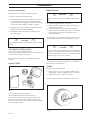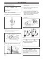
1
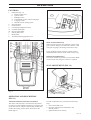
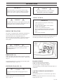
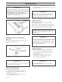
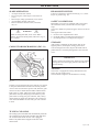
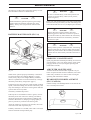
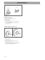
RBH 180
Operator´s manual
Please read these instructions carefully and
make sure you understand them before using
the machine.
101 89 59-26
Svenska –
Sve-5 225/232/235 Bruk
31
97-11-25, 08.46
31
TABLE OF CONTENTS
INTERNATIONAL SYMBOLS .......................................................................................
SAFETY RULES ...........................................................................................................
ASSEMBLY ...................................................................................................................
OPERATION .................................................................................................................
MAINTENANCE ............................................................................................................
ADJUSTMENTS ............................................................................................................
WIRING DIAGRAM .......................................................................................................
TROUBLESHOOTING GUIDE ......................................................................................
STORAGE .....................................................................................................................
TECHNICAL SPECIFICATIONS ...................................................................................
1
2
3
7
12
17
21
22
24
25
Read this manual carefully so that you will know how to assemble, use and maintain this unit.
Fill in and mail the registration card provided with the unit. For service other than described in this manual, contact an
authorized service dealer. He will provide you with parts and service.
Note: This lawn tractor is equipped with a combustion engine, which should not be used near any land covered with
grass or brush, unless the engine's exhaust system is equipped with a spark arrester meeting local laws. The operator
should maintain the spark arrester in effective working order.
INTERNATIONAL SYMBOLS
These symbols appear on your unit and in the supplied documentation.
You should learn and understand their meaning.
Read operator´s manual.
R N
Reverse
Engine start
Neutral
Transport
position
Brake to
STOP
Forward
Brake
release
Fast
Mower Height
Slow
Engine
Off
Reverse
Do not
smoke
Choke
Forward
Check
engine
!
Engine run
Noise
level
Keep hands out
Rotating
Blades
Clutch
Disengage
European
machinery
directive for
safety
Parking
brake
Never drive
across a slope
Brake
Warning
Never use the cutter if
there are people,
especially children, or
pets, in the vicinity.
Never leave
tractor when
running
Never
camy
passengers
Do not
raise up
English –
1
SAFETY RULES
These instructions are for your protection. You should read them carefully.
!
WARNING: This lawn tractor is able to cut hands, feet, and throwing objects. If you do not
follow the safety instructions, you could experience serious injuries.
1. GENERAL OPERATION:
• Know controls and how to stop quickly.
• Read, understand, and follow all instructions in the manual and on
the machine before starting.
• Only allow responsible adults, who are familiar with instructions, to
operate the machine.
• Wear safety glasses or eye shields when assembling or operating
the machine.
• Do not operate machine when barefoot. Always wear substantial
footwear, preferably steel-toed shoes.
• Do not wear loose fitting clothing that could get caught in moving
parts.
• Clear the area of objects such as rocks, toys, wires, etc., which
could be picked up and thrown by the blades.
• Be sure the area is clear of other people before mowing.
• Stop machine if anyone enters the area.
• Never carry passengers.
• Do not mow in reverse unless absolutely necessary.
• Always look down and behind before and while backing.
• Be aware of the mower discharge and do not point it at anyone.
• Do not operate the mower without the entire grass collector.
• Slow down before turning.
• Never leave a running machine unattended. Always turn off
blades, set parking, stop engine, and remove keys before
dismounting.
• Turn off blades when not mowing.
• Stop engine before removing grass collector.
• Mow only in day light or good artificial light.
• Do not operate the machine while under the influence of alcohol or
drugs.
• Watch for traffic when operating near or crossing roadways.
• Use care when mowing around a fixed object to prevent the
blades from striking it. Never deliberately run over any foreign
object.
• Use extra care when loading or unloading the machine into a
trailer or truck.
• Use care when pulling loads or using heavy equipment.
a. Use only approved drawbar hitch points.
b. Limit loads to those that you can safely control.
c. Do not run sharply. Use care when backing.
d. Use counterweights, wheel weight when suggested in
attachments instructions.
2. SLOPE OPERATION
Slopes are a major factor related to loss-control and tip-over accidents,
which can result in severe injury or death. All slopes require extra caution.
If you cannot back up the slope or if you feel uneasy on it, do not mow it.
DO
• Mow up and down, not across.
• Remove obstacles such as rocks, tree limbs, etc.
• Watch for holes, ruts, or bumps. Uneven terrain could overturn the
machine. Tall grass can hide obstacles.
• Use slow speed. Choose a low gear so that you will not have to
stop or shift while on slope.
• Follow the manufacturer's recommendations for wheel weights or
counterweights to improve stability.
• Use extra care with grass collector or other attachment.
This can change the stability of the machine.
• Keep all movements on the slope slow and gradual.
Do not make sudden changes in speed or direction.
• Avoid starting or stopping on a slope. If tires lose traction, turn off
the blades and proceed slowly down the slope.
DO NOT
!
2 – English
!
• Do not turn on slopes unless necessary, and then slowly and
gradually downhill, if possible.
• Do not mow near drop-off, ditches or embankments.
The mower could suddenly turn over if a wheel is over the edge of
a cliff or ditch, or if an edge caves in.
• Do not mow on wet grass. Reduced traction could cause sliding.
• Do not try to stabilize the machine by putting your foot on the
ground.
3. CHILDREN
Tragic accidents can occur if the operator is not alert to the presence of
children. Children are often attracted to the machine and the mowing
activity. Never assume that children will remain where you last saw them.
• Keep children out of the mowing area and under the watchful care
of another responsible adult.
• Be alert and turn machine off if children enter the area.
• Before and when backing, look behind and down for small
children.
• Never carry children. They may fall off and be seriously injured or
interfere with safe machine operation.
• Never allow children to operate the machine.
• Use extra care when approaching blind corners, shrubs, trees, or
other objects that may obscure vision.
4. SERVICE
• Use extra care in handling gasoline and other fuels.
a. Use only an approved container
b. Never remove gas cap or add fuel with the engine running.
Allow engine to cool before refuelling. Do not smoke.
c. Never refuel the machine indoors.
d. Never store the machine or fuel container inside where
there is an open flame, such as in water heater.
• Check fuel supply before each use allowing space for expansion
as the heat of the engine and sun can cause gasoline to expand
and overflow the tank.
• Use extra care when handling battery acid. Acid contact with skin
may cause severe burns. Eye contact may cause blindness.
• Use extra care when servicing the battery. Explosive gas is
produced in the battery. Do not service the battery while smoking
or near open spark or flame. This may cause the battery to
explode causing serious injury.
• Never run a machine inside a closed area. Exhaust fumes contain
carbon monoxide, an odourless and deadly gas.
• Keep nuts and bolts, especially blade attachments bolts, tight and
keep equipment in good condition.
• Never tamper with safety devices. Check their operation regularly.
• Do not change the engine governor settings or overspread engine.
• Reduce fire hazards. Keep machine free of grass, leaves, or other
debris build-up. Clean up oil or fuel spillage. Allow machine to
cool before storing.
• Stop and inspect the equipment if you strike an object. Repair, if
necessary, before restarting.
• Never make adjustments or repairs with the engine running.
• Grass collector components are subjects to wear, damage, and
deterioration, which could expose moving parts or allow objects to
be thrown. Frequently check components, and replace with
manufacturer's recommended spare parts, when necessary.
• Mower blades are sharp and can cut. Wrap the blades or wear
gloves, and use extra caution when servicing them.
• Check brake operating frequently. Adjust and service as required.
THIS SYMBOL MEANS THAT IMPORTANT SAFETY PRECAUTIONS HAVE TO BE
POINTED OUT. YOUR SAFETY IS INVOLVED.
ASSEMBLY
UNPACKING
STEERING WHEEL (FIG. 2)
The tractor is not completely assembled at the factory,
for transportation reasons.
After removing the packaging, check the machine for
any damage during the shipment, locate the hardware
bag and loose parts. Take care while removing the
machine from the pallet, to avoid any damage to the
mower deck.
STANDARD PACKING
•
•
•
•
•
•
•
•
tractor
steering wheel
seat with holder
battery
grass collector
trailer hitch
bag with operator's manual, parts manual,
2 keys for ignition, 1 decal with an arrow.
hardware bag for grass collector
IDENTIFICATION
The tractor identification plate is located under the
driver´s seat and behind the battery. Make a note of the
serial number on this page. This serial number will have
to be guoted when contacting your distributor for service
and ordering spare parts for the tractor. See fig. 1.
Fig. 2
Proceed to the following steps:
1. Straighten the front wheels.
2. Align the holes of the steering wheel with the
hole in the steering shaft.
MAKE SURE THE STEERING WHEEL IS
CENTERED AND THE HOLES LINED UP.
3. Insert the lock pin through the holes, and drive
it through the holes with a hammer.
SEAT (FIG.3)
Serial No.: ................................................................
Fig. 1: Identification plate
Fig. 3
Proceed to the following steps:
1. Discard the plastic protection from the seat.
2. Loosen both nuts from the seat hinges on the
tractor.
3. Place the seat and tighten securely with two
bolts, flat and spring washers.
4. Connect the safety switch.
English –
3
ASSEMBLY
TRAILER HITCH (FIG. 4)
The grass collector has been pre-assembled. However, to
assemble it correctly (to fit the collector cover with tractor
fenders). It is recommended to follow the instructions
below:
1.
Take the pre-assembled basket (item 1) out the box,
tilt the front tube (item 3), insert the upper bolts (item
2) and tighten loosely.
2.
Put the grass container, prepared in such a way, on the
basket supports on the rear part of the tractor and
adjust with the fenders. Tighten the bolts (item 2)
properly.
3.
Stretch the bag (item 3) with your hand and put it on
the rear handle, with the inlet hole of the basket
upwards. Insert the bottom tube (item 9) into the bag,
unscrew the nuts M5 of the bolts (item 10) under the
basket cover and insert the corner supports (item 8)
under the tubes at the top, screw on the nuts M5 on the
bolts (item 10) and (item 4) and tighten, loosely.
4.
Tilt the left and right supports (item 5). Put in place
the lower brace (item 7) from the outside of the grass
collector bag and secure them with screw (item 6)
loosely.
5.
Place the grass collector, hinge it on the tractor
supports and check the fit between the grass collector
cover and fenders. With a regard of the loose screws
you can adjust the fit between the cover and fenders.
6.
If it is not possible, with the help of the method above,
to accomplish the correct fit between the tube frame
and the tractor rear adjust, move the supports on the
tractor by moving them up or down.
7.
Remove the grass collector, tighten all screws securely
and fix the grass collector bag to the tube frame with
plastic clips.
8.
Slip the dumping lever (item 12) through the hole of
the collector cover and tube frame, secure it with
screws M5x 12 and nuts MS (the nuts are located
inside the tube).
Fig. 4
Proceed to the following steps:
1. Remove two bolts from the grass collector
support plate on the rear side of the tractor.
2. Place trailer hitch in place.
3. Replace bolts, washers and nuts.
Tighten securely.
GRASS COLLECTOR BAG (FIG. 5)
NOTE: After assembling check all the screws and nuts for
tightening.
Fig. 5
4 – English
ASSEMBLY
PLACING THE GRASS COLLECTOR ON
THE TRACTOR (FIG. 6)
PREPARATION BEFORE THE FIRST
OPERATION
The tractor is shipped without gas, oil and electrolyte in
the battery, for safety reasons.
!
DANGER
!
Lead acid batteries generate explosive gases. Keep
sparks, flame, and smoking materials away from
batteries. Always wear eye protection when around
batteries.
BATTERY PREPARATION
Fig. 6
Proceed to the following steps:
1. Lift the grass collector assembly with both
hands. Slant it to an angle of approximately 40°
(fig. 6).
2. Slide the grass collector on the two support
brackets located on the rear of the tractor.
3. When the grass collector is properly positioned,
place the decal with the triangle symbol directly
opposite to the symbol on the rear of the tractor.
This will assist alignment in the future (Fig. 7).
Battery provides maintenance free performance. Flush
cover battery is completely leakproof and spillproof
when tipped to a 45 degree angle, so you do not have to
worry about electrolyte leakage when performing routine
maintenance.
The battery is placed under the seat, and can be accessed
by tilting the seat in the upright position (Fig. 8).
NOTE: The battery is shipped with electrolyte!
DISTILLED
WATER
Fig. 8
Fig. 7
!
WARNING
!
This tractor is equipped with a safety micro-switch
and the cutting system will not function when the
grass collector assembly is not in place. Do not tamper
with this micro-switch.
English –
5
ASSEMBLY
REFUELLING
CHECK THE BATTERY
!
If it is necessary proceed to the following steps:
WARNING
!
1. Remove the battery from the tractor.
3. Charge the battery at a rate of 6 amps for 1 hour. Use
a 12-volt battery charger. Observe all precautions
required for battery charging. Complete the assembly
of your unit while waiting for battery to charge.
4. Check battery case for leakage to make sure that no
damage has occurred while handling.
5. Reinstall the battery and secure it with the spring
lever (see fig. 8).
!
DANGER
!
Make sure there is good air ventilation when refuelling.
1. Stop the engine and let it cool down.
2. Open the petrol cap slowly in order to release any
possible high pressure.
3. Tighten the petrol cap carefully after refuelling.
4. Dry around the area of the petrol cap. Clean the fuel
tank regularly. Impuritier in the tank can cause
running problems.
For refuelling, use approved container with funnel. Do
not overfill the tank, which contains approx. 7.7 litre.
Do not fill electrolyte into the battery while it is in the
tractor!
TO SERVICE THE ENGINE
NOTE: The engine is shipped with oil.
Fill crankcase with only 15W30 Oil. Do not overfill or it
causes serious damage to the engine.
!
DANGER
!
Use extra care in handling fuels. They are flammable,
vapours are explosive. Allow the engine to cool down
before refuelling. Do not smoke. Use safety approved
container only to store your gasoline.
Before starting the engine, read carefully the engine
manual.
GAS FILLING
In the operator´s manual for the engine, you will find
fuel and oil recommendations.
TYRES
Proceed to the following steps:
1. Check the tyres pressure: 100 kPa (1 BAR) for the
front wheels; 70 kPa (0.7 BAR) for the rear wheels.
2. Adjust pressure up or down if necessary.
NOTE: The tyre pressure is important for an even cut.
Fig. 9
Use only regular unleaded gasoline.
The recommended lowest octane level is 95.
If the engine runs on petrol with a lower octane level
than 95, an effect known as knocking can arise. This
leads to arise in the level of the engine temperature and
can cause engine failure.
Fig. 10
6 – English
OPERATION
CONTROLS
1.
2.
3.
4.
5a.
5b.
6.
7.
8.
Dash panel (fig. 11)
a. throttle control lever
b. ignition switch
c. headlight switch
d. switch MAN-AUTO, collector fill gauge
e. re-engage switch
f. ON/OFF switch, cutting system.
Steering wheel
Choke control
Cutting height adjustment lever
Forward speed pedal
Reverse speed pedal
Parking brake lever
Brake pedal
Transmission disengagement lever
Fig. 16
FRONT
MAN/AUTO SWITCH (d)
When in AUTO position, the automatic control of the
grass collector filling is set. When the collector is full
with grass clippings, the cutting system drive stops.
If it is the MAN position, then the overfill switch is
disabled and the collector tunnel could severely clog.
RE-ENGAGE SWITCH (e)
This switch should be pressed to re-activate the MAN/
AUTO switch, after the grass collector is emptied.
SEAT ADJUSTMENT (FIG. 12)
REAR
Fig. 11
OPERATION AND DESCRIPTION
(FIG. 11)
Fig. 12
TOGGLE SWITCH CUTTING SYSTEM (f)
The mower clutch switch is secured in the off position,
in order to avoid accidental engagement. To engage, pull
up the switch lever, and place it in the ON position; this
actuates the cutting system clutch, which drives the
blades (fig.16).
In order to adjust the seat, proceed to the following
steps:
1. loosen the thumb screw.
2. move the seat forward or backward to the
desired position.
3. tighten thumb screw securely.
English –
7
OPERATION
TO START THE ENGINE
!
DANGER
4. Place the throttle lever at the ”turtle” symbol. Pull the
choke control out.
!
Never run the engine indoors, or in enclosed or
poorly ventilated areas. Engine exhaust contains
carbon monoxide.
To start the engine, proceed as follows:
1. Open the fuel valve. The handle should point down
as shown in the fig.13.
5. Place the toggle switch ”cutting system” to OFF
position. Fig. 16, pos. OFF
6. Turn the ignition key to START position (Fig. 18)
release it immediately when the engine has started
(Fig. 18). Continuous cranking of more than 15
seconds per minute can cause the starter to overheat.
Allow the starter to cool down two minutes after
cranking of more than 15 seconds.
7. After starting the engine slide the choke control to
slow position and set the engine speed by the throttle
lever (Fig. 17).
Fig. 17
Fig. 13
2. Take a comfortable riding position on the seat.
The safety switch is connected.
Fig. 18
!
DANGER
!
When you want to start the engine, be sure that:
Fig. 14
3. Depress fully, and hold the brake pedal (fig. 14, pos
1).
•
the brake pedal is depressed
•
the mower clutch lever is in disengaged
position
•
the grass collector is properly in place
!
Fig. 15
8 – English
!
DANGER
Never run the engine indoors, or in enclosed or
poorly ventilated areas. Engine exhaust contains
carbon monoxide.
Keep feet, hands and clothes away from the engine.
The temperature of the muffler may exceed 80°C.
OPERATION
!
IMPORTANT
Move the throttle to slow position before turning
ignition off, in order to reduce muffler pop. Failure
to do so will result in engine and exhaust damages.
WARNING
!
While riding backwards, watch out behind.
Do not have your mower engaged!
LAWN CUTTING
!
WARNING
!
The mower deck must be in the highest position, when
you drive the tractor in transport mode off the lawn. If
not, damages will be caused to the blades.
IMPORTANT
•
•
•
•
•
RIDING THE TRACTOR
•
The tractor is equipped with a hydrostatic transmission.
It means that the forward and reverse speed can be
achieved with the use of the pedals (Fig. 15).
The more depressed the pedals are, the faster the tractor
moves. The tractor moves forward and reverse at the
same speed.
Clear the area of any objects, such as toys,
wires, branches, etc.
Do not wear loose clothes, which could be
caught in moving parts.
Always wear substantial footwear.
Keep out children and animals, while riding.
Keep hands and feet away from the mower
deck.
Never carry passengers.
Be sure the cutting system clutch is disengaged and is in
the OFF position before starting engine (fig. 16).
!
!
WARNING
In case the tractor must be pushed, the transmission
disengagement bypass lever must be put in the
forward position.
BRAKE (FIG. 14)
When the pedal is fully depressed, the brake is applied.
Then, place the throttle lever at the "turtle" idle position
(fig. 17).
The parking brake lever is used to lock the brake pedal
in brake position (fig. 14; pos. 2).
REVERSE GEAR (FIG. 15)
!
CAUTION
Fig. 16
BLADES CHECK
Check the cutting blades periodically.
If dull, you will not get a nice event cut.
You must replace or sharpen the blades.
After sharpening, you must balance the blades before reinstallation.
!
Come to a full stop before changing direction of
motion.
Depress slowly the reverse movement pedal
(Fig. 15, pos. 2).
CUTTING HEIGHT ADJUSTMENT
(FIG.19)
The cutting height lever is located on the right side of
fender.
The bottom position of the lever is the lowest cutting
height, and vice versa.
English –
9
OPERATION
IMPORTANT
In T-position the cutting system will STOP automatically and it will stay in the STOP status even when the
cutting height lever is lowered down again.
For the continuing- of the cutting you must push the
re-engage button (See Fig. 11, item 1. e).
4. Depress slowly the forward movement pedal to reach
the desired speed.
IMPORTANT
While starting the blades, keep the throttle in the
middle position, to save the belt and clutch from
premature wear and possible damage.
SPEED RANGES
The slowest speed is used for mowing on slopes or
mowing high wet grass.
The lower the grass is, the higher the speed should be.
When tractor is used for transport (not cutting). Depress
the forward movement pedal for maximum speed.
ALWAYS: In case of any obstacles, immediately
disengage the blades and lift the mower deck to the
highest level.
Fig. 19
MOWER DECK GAUGE WHEELS
(FIG. 20)
The mower deck gauge wheels must always be in the
lower position. Refer to fig. 20.
IMPORTANT
As soon as the blades strike any solid object the shear
bolts will break. Immediately stop the engine! Check
the blades! Replace the broken shear bolts only with
factory originals. Check to make sure that all blade
mounting bolts are tightened.
MOWING HINTS
1. We advise mowing the lawn in a longitudinal
and cross direction, overlapping previous cut,
which allows the lifting action of the blades into
the cutting path.
2. Forward speed of the lawn tractor must be
controlled in accordance with the type and
quantity of grass being mowed.
Fig. 20
IMPORTANT
Before starting cutting grass, take care of the proper
positioning of the grass collector.
RIDING AND MOWING
Proceed with the following steps:
1. Start engine and drive tractor to the lawn.
2. When on the lawn, engage mower clutch with
toggle switch (fig. 16).
3. Switch the MAN/AUTO button to the lower
AUTO position (fig. 11, d).
10 – English
IMPORTANT
The more grass that must be cut, the slower the
forward speed should be.
OPERATION
SLOPE OPERATION
HEADLIGHT SWITCH
•
•
Lights are switched on with the switch (fig. 11, c) if the
key is on position (fig. 18).
•
•
•
All slopes need extra caution.
Do not cut grass, when slope is more than 10°
(17%).
Mow slopes, riding up and down, never across.
Avoid sudden changes in direction.
Remove obstacles such as rocks, tree limbs,
ruts, etc.
!
WARNING
!
While travelling downhill, never coast! When
parking, depress the brake pedal, and lock it (fig. 14,
pos. 1 and 2).
SAFETY CONDITIONS
Remember your tractor is equipped with a seat switch;
this means that when you leave the seat, the engine
stops.
The mower blades stop when the grass collector is full of
grass.
The engine cannot start when:
a. the seat is not weighted with a driver
b. the break pedal is not fully depressed (Fig 14)
c. the cutting switch is in ON position (Fig 16)
STORAGE
COLLECTOR DISCHARGING (FIG. 21)
After cutting is finished, lift the mower deck to the
highest position, and stop the cutting system drive.
Turn off the ignition switch, depress the brake-clutch
pedal and lock it with the parking brake. Close the fuel
valve.
IMPORTANT
Always remove the ignition key, before storing. When
storing the tractor for longer periods of time disconnect the battery.
TOWING
The tractor is equipped for towing attachments in the
lower rear part of the tractor.
The maximum weight for the attachment is 150 Kg.
Fig. 21
In order to avoid clogging the grass collector, we suggest
to keep the MAN/AUTO switch in the AUTO position.
A micro switch controls this process and, when the grass
collector is full, it declutches the blades and the button
light comes on. Then, reduce the engine speed to idle,
pull out the telescopic dumping lever all the way and
push it down to empty the grass collector, then, slowly
release the lever upwards to allow the grass collector to
close. Push the RESET switch. Then, you can continue
to mow.
TUNNEL CLEANING
The cutting system will shut OFF automatically when the
rear collector bag is full. If the automatic shut OFF does
not work, then the tunnel air flow vent is plugged.
Remove any debris that is trapped in the area of the
microswitch..
English –
11
MAINTENANCE
CLEANING
!
ENGINE OPERATION
WARNING
!
Before cleaning, washing, servicing or repairing,
remove the ignition key!
Always wear substantial steel toe foot wear, gloves
and work clothes.
Be aware of any spilled fuel, oil or other contaminating substances.
After each cut, remove dirt and debris from the machine
surface, the discharge tunnel and the grass collector.
Follow the instruction described in the engine operator's
manual, for operation, service (air filter, fuel filter, oil
change, spark plugs, etc.)
CRANKCASE OIL CHANGE
Crankcase oil should be changed after the first 5 hours of
operation.
IMPORTANT
See engine operating and maintenance manual for
proper procedure.
WASHING (FIG. 22)
Your tractor is equipped with an oil drain plug.
Fig. 22
Proceed with the following:
1. Wash the tractor on a levelled surface, with
the grass collector mounted on.
2. Wash the inside of the mower deck, and the
discharge tunnel (engine off).
3. Dismount the grass collector, wash it, and
leave it off to let it dry.
4. Clean the plastic parts of the tractor with a
sponge and soap water.
IMPORTANT
Avoid water directly near the switches, the dash or
any electrical part.
!
BE CAREFUL
!
To clean the tractor never use high pressure washing
machines, or aggressive detergents.
12 – English
1. Place a flat bottom 2 litres container beneath the
oil valve.
Note: It may be necessary to raise the left side
of the tractor (with blocks under left wheels) to
get proper drainage.
2. Turn the oil valve counterclockwise, and pull
to drain oil.
Note: The oil fill cap should be loosened to
serve as an air vent.
3. To close oil drain valve, push and turn
clockwise.
4. Fill with grade SAE 30 or SAE 10W/30W oil.
5. Reinstall the oil cap.
6. Check that the crankcase oil is at the correct level on
the oil dip stick.
The warranty on this lawn tractor does not cover items
that have been subjected to operator abuse or negligence.
To receive full value from the warranty, operator must
maintain lawn tractor as instructed in this manual. The
following maintenance check list is supplied to assist
operator to properly maintain lawn tractor. This is a
check list only. Adjustments referred to will be found in
the Adjustment section of this manual.
MAINTENANCE
MAINTENANCE CHECKLIST
BEFORE STORAGE
BEGINNING EACH SEASON
EVERY 100 HOURS
EVERY 50 HOURS
EVERY 25 HOURS
MONTHLY
SERVICE RECORD
FREQUENTLY
FILL IN DATES
AS YOU COMPLETE
REGULAR SERVICE
AFTER FIRST 20 HOURS
AFTER FIRST 5 HOURS
AFTER FIRST 2 HOURS
BEFORE EACH USE
Check engine oil level
l
l
l1,2
l
Change engine oil
l
l l
l1,2
Change spark plug
Replace air filter paper cartridge
l2
Clean air screen
l
Inspect muffler/spark arrester
l
Replace fuel filter
Check battery fluid level/recharge
l
Clean battery and terminals
l
Check brake operation
l
l
l
l
l
Check transmission cooling
Check tire pressure (Fr: 1 bar; Rr: 0,7 bar)
l
l3
Sharpen or replace mower blades
Check for loose fasteners
l
l
l
l
Clean lawn tractor
l
l
Disconnect battery cables
l
See lubrication chart
Adjust mower deck drive cog belt
l
l
l
l
NOTES: 1. Change more often when operating under a heavy load or in high temperatures (35°C and above). 2. Service more often
when operating in dirty or dusty conditions. 3. Replace more often when mowing in sandy soil.
TO BLOCK UP THE TRACTOR
When the tractor is to be blocked up, use a jack lift it on
support stands. Block up the tractor as follows:
1. Place a jack under the rear axle transmission and lift
the rear end of the tractor.
2. Place two stands under the rear axle, one stand at the
inner side of each rear wheel.
3. Lift the front end and place two stands under the
front axle beam, one stand at the inner side of each
wheel spindle.
CAUTION
At no time during maintenance or adjustment, the
tractor can be lifted more than 50 cm from level
position, without taking the following precautions:
1. Remove fuel from the tank and run the
engine until the carburettor is dry.
2. Remove battery (See Battery removal
paragraph in the Maintenance section).
3. Remove oil from crankcase.
LUBRICATION
For lubrication frequency see Maintenance check list.
For lubrication points and type of lubricant, see Lubrication chart. The transmission has been lubricated for life.
ENGINE MAINTENANCE
See Engine operating and maintenance manual for
maintenance instructions.
English –
13
MAINTENANCE
LUBRICATION (FIG 23)
Fig. 23
LUBRICATION LIST
Item
Name
1
2
3
4
5
6
7
8
9
10
11
12
13
14
15
16
Front wheel - grease fitting
Steering ball-joints
Steering sector gear
Steering pinion gear
Steering shaft bearing
Steering shaft bearing
Movement lever - grease fitting
Shaft hub for lifting the mower deck
Moving ling ball-joints
Brake pedal hub
Parking brake ring
Steering bearing
Left & Right spindle - grease fitting
Mower deck hinged pin
Front axle pivot pin + grease fitting
Diagonal shaft - grease fitting
14 – English
Number
Term-hours
Lubricant
2
4
1
1
1
1
1
1
4
2
1
1
2
6
2+1
2
25
50
50
25
50
50
50
50
50
50
50
25
25
when dismounted
when dismounted +50
25
Grease
Oil
Grease
Grease
Oil
Oil
Oil
Oil
Oil
Grease
Oil
Grease
Grease
Grease
Grease
Grease
MAINTENANCE
!
The bearings in idler pulley and retainer pulleys are life
time lubricated. Gear box is filled with oil.
!
DANGER
!
Lead acid batteries generate explosive gases. Keep
sparks, flame and smoking materials away from
battery. Always wear eye protection when around
batteries.
!
Be sure to reinstall battery in the same position and
properly reconnect battery cables (red to positive,
black to negative).
Proper care will lengthen battery life. When replacement
becomes necessary, use battery of same size and type for
continued trouble-free service (see Repair parts manual).
!
BATTERY MAINTENANCE (FIG. 24)
DANGER
DANGER
!
Always disconnect negative (black) cable first.
Removing positive cable first can result in sparks if
the wrench touches any metal surface. Be sure battery
hold-down bracket does not touch battery terminals
and causes a spark.
!
DANGER
!
Always connect positive (red) cable first. Connecting
negative cable first can result in sparks if the wrench
touches any metal surface. Be sure battery hold-down
bracket does not touch battery terminals and causes a
spark.
SPARK PLUG MAINTENANCE
Spark plug should be checked periodically for excessive
carbon and gap. Use a wire feeler gauge to check spark
plug gap and set 0,7 mm (see Engine operating and
maintenance manual).
Fig. 24
When starter operates properly and battery connections
are clean and tight, but cranking difficulty is experienced, battery may not be charged. Battery should be
taken to a qualified service station and tested, or charge
the battery with battery charger (See page 7)
If engine will not start right away under normal cranking
speed, continued cranking will run down the battery and
may cause damage to the starter. Check ignition and fuel
systems and correct any faults.
AIR FILTER MAINTENANCE
Air filter should be cleaned and/or replaced every 25
hours of operation under normal conditions; more often
under dusty conditions. To clean air filter see Engine
operating and maintenance manual.
HEADLIGHT BULB REPLACEMENT
(FIG. 25 AND 26)
Lift the hood up. The headlight bulbs are secured in the
sleeve with bayonet sockets.
The battery should be kept clean.
If the top has an accumulation of dirt or grease, remove
the battery from lawn tractor for cleaning. The battery
should be cleaned with a mild solution of baking soda
and water. Brush this on, keeping vent plugs tightly in
place to prevent any solution from entering cells.
Allow the solution to work for a few minutes, then rinse
with clean water and wipe battery dry.
If battery terminals are corroded, clean with a wire brush
and coat terminals with petroleum jelly.
Fig. 25
English –
15
MAINTENANCE
Fig. 26
FUSE EXCHANGE
The fuse box is placed under the dash.
Proceed as follows:
1. Lift the hood up.
2. Pick out the fuse and replace it by another one
of the same value (15A).
If it is still impossible to start the engine, call
your service dealer.
WHEEL EXCHANGE (FIG. 27)
Fig. 27
Proceed as follows:
1. Switch off ignition.
2. Lift up the tractor and place it on stands.
3. Remove plastic cover.
4. Dismount the retaining ring, the flat washer, and
remove the wheel. Note: For a rear wheel,
watch the key and the key groove.
16 – English
ADJUSTMENTS
TRACTOR BRAKE ADJUSTMENT
(FIG. 28)
THE GRASS COLLECTOR OVERLOAD
WARNING SYSTEM (ZP 98/1 MODEL)
Your tractor is equipped with a disc brake mounted on
the transaxle.
Important note: This system only works in "AUTO"
switch position. (see operations/controls section of
manual).
The grass collector capacity has been designed to hold a
substantial volume of grass.
The overloading of this intended capacity may result in
clogging of the discharge tunnel creating a potentially
hazardous condition. As a safety precaution, the tractor is
equipped with an overload warning system.
As a result of an acumulation of a predetermined volume
of grass clippings an overload protection switch located
inside the grass collector will be mechanically activate.
The signal from this switch is interpreted by the
"SMART CONTROL MODULE" distinguishing
between random impulse actuation which are ignored &
only accepting signals exceed a minimum of 1 second +
to prevent nuisance activation.
An audible warning device "BUZZER" will be activated
providing an intermittent "BEEP" for a 3 second duration. The cutting system will be automatically switched
off at the end of the "BEEP" cycle indicating that the
grass collector must be emptied prior to continuing
further.
To check the brake operation:
1. Place the tractor on a flat surface, and stop the
engine.
2. Place the shift control lever in neutral position.
3. Depress the brake pedal enough to latch the parking
brake lever in the engaged position (refer to Fig. 14).
4. If you cannot push the tractor, the brake is adjusted
correctly and is functioning.
5. If you can push the tractor, the brake is too loose and
should be tightened.
To adjust loose brake:
1. Place the shift control lever in neutral position,
and depress the brake pedal to latch the parking
brake lever in the engaged position.
2. Turn the brake adjusting nut clockwise until you
cannot push the tractor.
3. Check again the tractor brake adjustment, as
described above.
To adjust tight brake:
1. Place the shift control lever in neutral position.
2. Turn the brake adjusting nut counterclockwise,
until you can push the tractor.
3. Check again the tractor brake adjustment.
While operating the tractor, check the stopping
distance. If the tractor requires more than 1
meter to stop at high speed in the highest gear,
the brake must be adjusted.
Fig. 28
TEST PROCEDURE TO VERIFY
PROPER FUNCTION OF THE
OVERLOAD WARNING SYSTEM
Since this system is considered to be an important safety
feature, it is recommended that the following test
procedure be performed on a regular basis very carefully
following all the necessary safety regulations & precautions.
The battery must be fully charged prior to this test.
The "AUTO-MAN" switch must be in the "AUTO"
position.
Insert the ignition key & start the engine.
Switch on the cutting system.
Manually activate & maintain in this position for the
duration of this test the overload protection switch
located inside the grass collector.
The audible warning "BUZZER" signal cycle should
start after the 1st second.
After a 3 second period both the "BUZZER" & the
cutting system will stop operating.
The warning system is in functional order if all of the
abov e steps have been complete as indicated above.
Please consult your local dealer if the test procedure
was not completed successfully.
The cutting system can be re-activated after emptying of
the grass collector by either one of the following options:
Activate the "RESET" switch or
Turn of & then on again the switch for the cutting
system engagement.
English –
17
ADJUSTMENTS
SERVICING
SHEAR PINS (FIG. 30)
In the event of system failure, there is a manual position
"MAN" switch option which allows for a temporary
over-ride of the overload warning system. It is recommended that this be only used as a back-up & only until
necessary repairs can be arranged. A temporary by-pass
service connector has been included in the original
tractor kit & should be installed while the system is
being serviced. This service connector will provide a
shunt path & will shut-off hte cutting system immediately upon receiving a signal from the collector overload
switch indicating a full grass collector condition.
IMPORTANT
As soon as the blades strike any solid object the shear
bolts will break. Immediately stop the engine! Check
the blades! Replace the broken shear bolts only with
factory originals. For installation refer to fig. 30.
Check to make sure that all blade mounting bolts are
tightened.
Fig. 30
BLADE SHARPENING
IMPORTANT
To remove blades:
1. Remove the mower deck.
2. When replacing the blades, be sure all parts are
reassembled in proper order and securely
tightened, or severe vibrations will occur (See
fig. 30). Bent tip edges of blades must be toward
top of the mower deck, or blades will not cut.
!
IMPORTANT
!
The right blade has a left hand thread bolt.
!
DANGER
!
Do not handle the blades with bare hands. Wear
gloves or wrap the blades with newspaper or other
material while removing or installing the blades.
3. Reinstall the mower deck.
Great care should be taken to keep the blades
balanced. An unbalanced blade will cause excessive
vibrations and eventual damage to the engine or the
mower.
1. The blade can be sharpened with a file or on a
grinding wheel. Do not attempt to sharpen while
on mower.
2. Place the center hole of the blade over the end
of a screwdriver, placed horizontally. If the blade
is balanced, it should remain in a horizontal
position. If either end of the blade moves
downward, sharpen the heavy end until the
blade is balanced.
DRIVE BELTS ADJUSTMENT
(FIG. 31, 32 AND 33)
IMPORTANT
The life time of the belts and their proper operation
depends on their right adjustment. After a few hours
of operation, they must be inspected and may need
adjustment.
The three belts are located beneath the main frame. One
belt drives the transaxle. The other one transmits the
power from the clutch to the mower deck. The third one
drives and synchronizes the two blades together.
18 – English
ADJUSTMENTS
TRANSMISSION DRIVE BELT (FIG. 31)
A. CUTTING OAN REMOVAL (FIG 41)
1. Lower the cutting pan to the lowest position.
2. Pull idler arm assembly in and remove V belt
17x1400 from pulley.
3. Disconnect the spring from the engagement lever.
Fig. 31
1. engine pulley
2. pulley
3. idler pulley
Adjust the tension of the belt with the pulley 3.
MOWER CLUTCH BELT (FIG. 32)
The tension of the belt is automatically adjusted with the
spring loaded idler pulley.
Fig. 41
4. Disconnect the plug connector from the air valve
switch in tunnel.
5. Lift tunnel to release the lower part from the two
welded pins that connect it to the mower deck
assembly.
6. Pull out tunnel rearwards approximately 10 cm.
Secure the tunnel to prevent it from falling back
down.
7. Remove the hair pin clips from front pin and from the
two rear pins.
NOTE: Altjough it is not necessary, it is recommended to loosen the large spring for safety and to
facilitate reinstalation of cutting pan.
8. Pull out rear pin from one side and then use a pair of
pliers to pull second rear pin from other side.
Fig. 32
TRANSMISSION DRIVE BELT (FIG 31)
1.
2.
3.
engine pulley
pulley
idler pulley
Adjust the tension of the belt with the pulley 3.
MOWER CLUTCH BELT (FIG 32)
The tension of the belt is automatically adjusted with the
spring loaded idler pulley.
MOWER DECK BELT (FIG. 33)
ADJUST THE MOWER COG BELT
NOTE: It is recommended that the mower cog belt be
adjusted after 20 hours of operation as the new belts will
stretch slightly during the initial break in period.
CAUTION
If the large spring has not been loosened, the pivot
arm assembly will not spring up with force. Do not
place hands or fingers above the pivot arm assembly
and use pliers when pulling out second rear pin.
9. pull out fron pin
10. Remove V-belt from electro magnetic clutch
11. Slide cutting pan out from side of tractor
B. ADJUSTMENT PROCEDURES FOR
COG BELT TENSION
1. Remove cutting pan from tractor, follow procedure
described in A.
2. Remove V-belt pulley and idler arm assy.
3. Remove plastic belt cover.
4. Loosen the two hex nuts on the cog idler pulley on
English –
19
ADJUSTMENTS
tension bracket idler.
5. Adjust nut M10 until the specified tension at cog belt
is reached. (See Fig 33)
6 Re-tighten the two hex nuts on the cog idler pulley
and the belt is now adjusted correctly.
7. To re-install the cutting pan - reverse the procedure.
Note: It is possible but not desirable to adjust the cog
belt tension without removing the cutting pan assembly
form the tractor. In this case follow step 2 through 8
from the above procedures.
DANGER
This cog belt must be properly adjusted. If not, the
blades can contact and the belt will be destroyed and
the cutting system will be damaged.
TORQUE SPECIFICATIONS
Cutting system:
Mower cog belt
Blade bolt LH
Blade bolt RH
Housing bolts M8x30
Self locking nut M12
(Pulley)
Hexagon socket screw
M8x20 (Idler arm)
Steering tooth gear fasteners:
Screw M8x30
Lock nut M12
Engine-transmission drive:
Exhaust screws
Crank shaft bolt
Screw M10x55
(Idler pulley-front)
Fig. 33
DANGER
On impact with any hard objects, the blade shear bolts
will break and the cog belt will be damaged!
The cog belt must be inspected.
Be careful!
The two blades must be positioned 90 degrees to each
other.
Replacement:
Use always genuine parts.
Fig. 34
20 – English
See Fig 33
50 Nm
50 Nm
32 Nm
65 Nm
25 Nm
15 Nm
80 Nm
16 Nm
108 Nm
25 Nm
WIRING DIAGRAM
1.
2.
3.
4.
5.
6.
7.
8.
9.
10.
11.
12.
13.
14.
15.
16.
17.
18.
29.
20.
Battery
Engine
Ignition switch
Starter relay
Starter
Magnetic clutch (diode + resistor)
Headlights
Seat switch
START-CUT switch
AUTO-MAN switch
Brake switch
Relay for seat switch
Grass collector switch
Headlights switch
Fuse 15 A and 5A
Grass collector tunnel microswitch
Re-engage switch
T position switch
T position relay
Buzzer box
COLOR LEGEND OF WIRES:
B
- BLUE
R
- RED
BR
- BROWN
W
- WHITE
BLK - BLACK
Y
- YELLOW
GRN - GREEN
V
- VIOLET
GRY - GREY
LTB
- LIGHT BLUE
English –
21
TROUBLESHOOTING GUIDE
PROBLEM
CORRECTION
Mower cuts ragged or
uneven
1.
2.
3.
4.
5.
6.
7.
Mower leaves
unmowed strip
between blades
1. Mowing a heavy stand of grass or grass with excessive surface moisture could allow mower to leave an
unmowed strip.
2. Forward speed should be adjusted to mowing conditions by gear selection. Engine should be run at full
throttle.
3. Make sure blades are sharp and in good condition. Replace if necessary.
4. Check blade belt tension. Adjust if necessary.
5. Check quill assemblies for damage or wear. Replace if necessary.
6. Check for damage to mower deck housing. Repair if necessary.
Mower scalps lawn
1. Check mower height adjustment setting and readjust if neaded. Scalping is more likely on rough or uneven
lawns.
2. Check for damage to mower deck housing. repair if necessary.
3. Check for bent blades or quills assemblies. Replace if necessary.
4. Check mower deck leveling adjustment and adjust if necessary.
Mower will not
discharge clippings
1. Remove any accumulation of grass clippings from underside of mower deck housing.
2. Wet conditions can cause the discharge funnel and underside of mower deck to become plugged with
clippings. Do not mow wet grass.
3. Forward speed should be adjusted to mowing conditions by gear selection. Engine should be run at full
throttle.
4. When mowing long grass make first cutting in high position, then recut at normal cutting height.
5. Check drive belt tension per manual. Adjust if necessary.
6. If blades have been replaced, make sure they have been properly mounted.
Blade drive belt comes
off during use
1. Blade drive belt may suffer internal damage to cords when it comes off during use. If belt comes off after
checking all steps below, replace with a new original equipment belt.
2. Check belt tension per manual. Adjust if necessary.
3. Check belt guide. Correct clearance is 1,5 mm from belt when blade engage lever is engaged.
4. Check mower deck leveling adjustment per manual. Adjust if necessary.
5. Check for and remove any foreign objects interfering with belt travel.
6. Check all pulleys on mower deck. A bent or split pulley could cause problems. Replace if necessary.
7. Check engine drive pulley inner surface. If inner surface is rough or split, pulley should be replaced.
8. Check blade engagement idler assembly for wear. Replace necessary parts.
Blade drive belt slips
1.
2.
3.
4.
If grass is too high or wet, belt slippage may occur.
Check belt for wear or damage. Replace if necessary.
Check blade belt tension per manual. Adjust if necessary.
Check blade drive belt tension spring. If spring is stretched or damaged, replace spring.
Blade drive belt wears
excessively
1.
2.
3.
4.
5.
6.
Check all belt guides. Correct clearance is 1,5 mm from belt when blade engage level is engaged.
Check for and remove any foreign objects interfering with belt travel.
Check pulleys for damage. Replace if necessary.
Make sure blade brake is clearing belt when mower clutch lever is engaged. Adjust or replace if necessary.
Make sure mower deck leveling adjustment is correct. Adjust when necessary.
Check blade belt tension per manual. Adjust if necessary.
Blades will not engage
1. Check belt. If worn or broken, replace. If belt is too loose, make belt adjustment.
2. Check engagement spring on deck engagement idler. If broken or damaged, replace.
3. Check for and remove any foreign objects interfering with engagement idler travel.
22 – English
Remove any accumulation of grass clippings from underside of mower deck housing.
Make sure blades are sharp and in good condition (not bent or incorrectly mounted).
Check blade mounting screws. Blade screws must be tight.
Check mower deck leveling adjustment per manual. Adjust if necessary.
Check blade belt tension per manual. Adjust if necessary.
Check quill assemblies for damage or wear. Replace if necessary.
Check for possible damage to mower deck housing. Repair or replace if necessary.
TROUBLESHOOTING GUIDE
PROBLEM
CORRECTION
Extreme vibration
occurs when blade is
engaged
1.
2.
3.
4.
5.
6.
7.
8.
Check blades and make sure they are not bent, out of balance or loose. Replace if necessary.
Check belt for burn spots or irregularities that might cause vibrations. Replace if necessary.
Check quill assemblies for damage or wear. Replace if necessary.
Check for worn or damaged blade engagement parts. Repair or replace if necessary.
Check engine drive pulley inner surface. If inner surface is rough or split, pulley should be replaced.
Check under side of mower deck housing for accumulation of clippings. Remove accumulated clippings.
Check for loose or damaged engine mounts. Tighten or replace as necessary.
Check blade belt tension per manual. Adjust if necessary.
Unit drive belt slips
1.
2.
3.
4.
5.
6.
Check unit drive belt adjustment. Ajust if necessary.
Check for damaged or broken clutching idler spring. Replace if necessary.
Check belt for wear or damage. Replace if necessary.
Check for and remove any foreign objects obstructing clutching idler mechanism.
Check for split engine or transmission pulley. Replace if necessary.
On Shift-on-the-Go units, check for proper free play in cable adjustment.
Mower scalps lawn
1. Check mower height adjustment setting and readjust if needed. Scalping is more likely on rough or uneven
lawns.
2. Check for damage to mower deck housing; repair if necessary.
3. Check for bent blades or quill assemblies. Replace if necessary.
4. Check mower deck levelling adjustment and adjust it if necessary.
Unit drive belt squeals
when brake is applied
1. Check lawn tractor drive belt adjustment and lawn tractor brake adjustment per manual. Adjust if necessary.
2. Check for and remove any foreign objects obstructing clutching idler mechanism.
Unit drive belt comes
off during use
1.
2.
3.
4.
Unit will not propel
itself when clutch is
engaged
1. See steps 1 through 5 in Unit drive belt slips section of this chart.
2. Check engine, transmission or transaxle pulley for sheared or missing key. Replace if necessary.
3. Check transaxle to make sure it is operable.
Extreme vibration
occurs when clutch is
engaged
1.
2.
3.
4.
Unit will not shift or
shifts hard
1. Check shifting procedure.
2. Check lawn tractor drive belt adjustment and lawn tractor brake adjustment per manual. Adjust if necessary.
3. Have transaxle checked by an authorized service dealer.
Steering slips or is
loose
1. Check for steering sector gear and pinion looseness. If gears are loose, make sector gear adjustment.
2. Check ball joints for wear. Replace if necessary.
Engine will not turn
over
1.
2.
3.
4.
5.
6.
7.
Check starting procedure. Make sure starting instructions are followed.
Check fuse.
Check battery for charge. Make sure battery has been activated and charged.
On new units, remove spark plug and check cylinder for accumulation of oil due to improper handling.
Make visual check of electrical system to make sure all connections and lockout switches are secure.
Check engine according to engine manufacturer’s instructions.
Have electrical system checked by an authorized service dealer.
Engine turns over but
will not start
1.
2.
3.
4.
5.
6.
7.
8.
Check starting procedure. Make sure starting instructions are followed.
Make sure fuel tank is filled with clean, fresh fuel.
Make sure fuel shut-off is open.
Make sure that throttle is in start or fast position.
Check engine according to engine manufacturer’s instructions.
Have wiring and lockout switches checked by an authorized service dealer.
Check fuel filter for obstructions.
Check for choke usage.
Blocked discharge
funnel
1. Take away the grass collector, and clean the discharge tunnel.
Check belt tension. Adjust if necessary.
Check belt guides. Adjust if necessary.
Check for split or damaged pulleys. Replace if necessary.
Check clutching idler pulley alignment. If out of alignment, idler bracket may be bent. Replace if necessary.
Check for split or damaged pulley. Replace if necessary.
Check belt for irregularities or burned spots. Replace if necessary.
Make sure belt tension is correct. Adjust if necessary.
Check clutching idler assembly for wear or damage. Replace parts if necessary.
English –
23
STORAGE
The tractor should be immediately prepared for storage
at the end of the season, or if the unit is to be unused for
30 days or more. Fuel, if permitted to stand unused for
extended periods (30 days or more), may develop
gummy deposits which can adversely affect the engine
carburettor and can cause engine malfunction.
DANGER
Never store engine with fuel in tank indoors or
poorly ventilated enclosures, where fuel fumes may
reach an open flame, spark or pilot light as on a
furnace, water heater, clothes dryer, etc...
Handle fuel carefully. It is highly flammable and
careless use could result in serious fire damage to
your person and property.
Drain fuel into an approved container outdoors away
from open flame.
To prepare the tractor for storage, proceed as follows:
1. Clean the tractor thoroughly.
2. Inspect the tractor for worn or damaged parts
and tighten all loose screws and nuts.
3. Prepare engine for storage (See the engine
operating and maintenance manual).
4. Lubricate all points shown in the Lubrication
24 – English
´*2°z¶1[¨
Chart (page 16).
5. Remove the battery (See the Battery removal
paragraph, in Assembly section of this manual).
6. Clean the battery as described in the Battery
maintenance paragraph of the Maintenance
section of this manual. Add clean water to raise
level to indicator ring and fully charge the
battery. A discharged battery will freeze and may
burst. If possible, place the battery in a cool, dry
area. Charge the battery overnight every 30
days.
7. Store the tractor in a clean, dry area, and cover
it for additional protection.
A yearly check-up or a tune-up by an authorized service
dealer is a good way of insuring that your tractor will
provide maximum performance for the next season.
NOTE: Fuel stabilizer is an acceptable alternative in
minimizing the formation of gum deposits during
storage. Add stabilizer to the fuel in the fuel tank or
storage container. Always follow the mix ratio given by
the stabilizer manufacturer. Run the engine at least 10
minutes after adding stabilizer to allow the stabilizer to
reach the carburetter. Do not drain the gas tank and
carburetter if using stabilizer.
TECHNICAL SPECIFICATIONS
Engine:
18 HP VANGUARD V-TWIN Briggs & Stratton *
Battery:
12 Volts/22 Ah
Front tyres:
16 X 6.50 - 8
Rear tyres:
20 X 10.00 - 8
Front tyres pressure:
100 kPa (1 Bar)
Rear tyres pressure:
70 kPa (0,7 Bar)
Transaxle:
Forward speed
Reverse speed
HYDRO-GEAR MODEL NO: 310-0650
0 - 9 km/h
0 - 4 km/h
Turning radius:
74 cm
Cutting heights:
6 heights: from 25 to 90 mm
Mowing size:
Twin-blade; 102 cm
Mower deck:
Suspended
Blade clutch:
Warner Electro-magnetic clutch
Discharge:
Rear, with grass collector as standard
Weight (18 HP):
Gross: 262 Kg
Tractor dimensions (L x W x H):
240 x 106 x 110 cm
Net: 247 Kg
IMPORTANT
* Refer to model and type numbers when purchasing replacement parts.
For improvement purposes, specifications and design are subject to change, without notice.
Please be advised that no legal claims, of whatsoever they might be, can be used upon the information contained in this
manual.
When performing repairs, make sure that only genuine parts are used. Use of non-original parts will void the warranty.
English –
25
26 – English
´*2°z¶1[¨