1
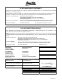
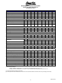
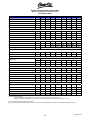
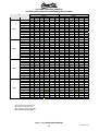
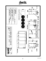
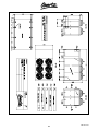
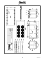
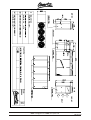
QLAC
TECHNICAL MANUAL
AIR COOLED WATER CHILLERS AND HEAT PUMPS WITH AXIAL FANS
06617645-02
TEV LTD, ARMYTAGE ROAD, BRIGHOUSE, WEST YORKSHIRE, HD6 1QF. TEL: + 44 (0) 1484 405630 FAX: +44 (0) 1484 405620
EMAIL: [email protected] WEB: www.quartz.co.uk
INDEX
Page
Declaration of conformity
3
Technical features
4
Technical data
7
QLAC LS cooling capacities and compressor input power
12
QLAC /HP/LS heating capacities and compressor input power
17
Evaporator pressure drops
19
QLAC K1 – K2 Water pumps - available static pressure
20
Free cooling capacities
21
Correction tables
23
Electrical data / Sound levels
24
Installation instructions – general
25
Lifting and handling
25
Location and minimum technical clearances
25
Hydraulic connections
26
QLAC FC Free cooling version
27
Condensing pressure control
27
Operational limits
27
Electrical connections
28
Start up
28
Control and safety device settings
29
Maintenance and periodic checks
30
Refrigerant circuit repair
30
Environmental protection
31
Decommissioning
31
Dimensions
32
2
06617645-02
EC DECLARATION OF CONFORMITY
Herewith TEV Ltd declare that the air conditioning equipment designated below is in accordance with the essential
requirements of current EC Directives.
This declaration is based on the design and construction of the equipment in the form brought onto the market by TEV Ltd.
If alterations are made to the machinery without prior consultation with TEV Ltd. this declaration becomes invalid.
Relevant EC Council Directives:
Applied harmonised standards:
Basis of self attestation:
Machinery Directive (98/37/EC)
EMC Directive (89/336/EEC in the versions 93/68/EEC)
Low Voltage Directive (73/23/EEC in the version 93/68/EEC)
Directive PED (97/23/EC)
EN 292-1:1991, EN 292-2:1991, EN 294:1992, EN 349:1993, EN 55014-1:2000,
EN 55014-2:1997, EN 60335-1:2002, EN 60335-2-40:2003, EN 61000-3:1995
BS EN ISO 9001:2000
BSI registered firm certificate no. FM671
EG KONFORMITÄTSERKLÄRUNG
Hiermit erklärt TEV Ltd, daß die unten angegebenen Klimageräte in Übereinstimmung mit den Gesundheits - und
Sicherheitsbestimmungen der gültigen EG-Direktiven stehen.
Diese Erklärung bezieht sich auf die Konzeption und die Konstruktion der Geräte, die von TEV Ltd. auf den Markt gebracht
werden.
Wenn Veränderungen an den Geräten ohne vorherige Absprache mit TEV Ltd. gemacht werden, so wird diese Erklärung
ungültig.
Relevante EG Richtlinien:
Angewandte Standard
Normen:
Bestätigungsgrundlage:
Maschinen - Richtlinien (Version 98/37/EWG)
EMV Direktive: (89/336/EWG/EEC in den Versionen 93/68/EWG)
Niederspannungsrichtlinie: (73/23/EWG/EEC in der Version 93/68/EWG)
Richtlinien PED (97/23/EC)
EN 292-1:1991, EN 292-2:1991, EN 294:1992, EN 349:1993, EN 55014-1:2000,
EN 55014-2:1997, EN 60335-1:2002, EN 60335-2-40:2003, EN 61000-3:1995
BS EN ISO 9001:2000
Zertifikat Nr. FM 671
Model Name:
Nom du modèle:
Nombre del Modelo:
Machinebeschrijving:
Modellname:
Serial Number:
Numéro de série:
Numéro de Serie:
Serienummer:
Serienummer:
Model Part Number:
Référence du modèle:
Artikelnummer:
Modellnummer:
Número de la Parte del Modelo:
Signature of TEV Ltd.
"responsible person":
designated Handtekening van de
persoon bij TEV Ltd.:
Signature d' TEV Ltd Le responsable:
gemachtigde
Unterschrift von TEV Ltd.
"verantwortliche Person":
Firma de TEV Ltd. designado como
"persona responsable":
(A C HAMMERSLEY)
Position of Signatory:
Fonction du signataire:
Cargo del firmante:
Functie van gemachtigde
Position desUnterschreibenden:
3
MANUFACTURING DIRECTOR
DIRECTEUR DE FABRICATION
DIRECTOR FABRICACIÓN
PRODUKTIE COÖRDINATOR
PRODUKTIONS DIREKTOR
06617645-02
TECHNICAL FEATURES
Frame
All QLAC unit enclosures are manufactured from hot-galvanised sheet steel, painted with polyurethane
powder enamel and stoved at 180°C to provide a durable, corrosion resistant finish. The frame is selfsupporting with removable panels. All screws and rivets are made from stainless steel. The paint colour is
RAL 7035.
Refrigerant circuit
Refrigerant is R407C. The refrigerant circuit is assembled using quality brand components and in
accordance with ISO 97/23 concerning welding procedures. Model sizes 140 and upwards have multiple
refrigerant circuits. Each refrigerant circuit is totally independent of the other. Failure of one circuit does not
influence the other circuit. The refrigerant circuit includes:
Liquid line manual shut-off valve
Sight glass
Filter drier
Thermal expansion valve with external equalizer
Electronic expansion valve with control to optimise efficiency in part load conditions (option)
Reversing valve (heat pump version only)
Non return valve (for heat pump version only)
Liquid receiver (for heat pump version only)
Schraeder valves for maintenance and control
Pressure safety device (according to PED requirements)
Compressors
Scroll compressors are used, each fitted with a crankcase heater and provided with thermal overload
protection via a klixon embedded in the motor winding. Compressors are mounted in a separate chamber in
order to be separated from the air stream and to enable maintenance to be performed whilst the unit is still
operating. The crankcase heater is always powered when the compressors are in stand-by. All compressors
are in tandem configuration. This creates higher efficiencies uring part load conditions compared to units
with independant refrigeration circuits per compressor.
Condensers
Condensers are made of copper tubes and aluminium fins. The diameter of the copper tubes is 3/8” and the
thickness of the aluminium fins is 0.1 mm. Tubes are mechanically expanded into the aluminium fins to
maximise heat transfer. The geometry of these condensers guarantees a low air side pressure drop and
allows the use of slow running (and low noise) fans. The condensers can be protected by a metallic filter
(option).
Fans
Fans are axial type with aerofoil blades. They are statically and dynamically balanced and supplied complete
with safety fan guard that complies with the requirements of EN 294. They are mounted on the unit frame
using rubber anti-vibration mounts. The electric motors are 6 pole (approx. 900 rpm) in the low noise version
and 8 pole (approx. 750 rpm) in the extra low noise version. The fans are directly driven and are fitted with
integral overload protection. Motors have moisture protection to IP 54.
4
06617645-02
Evaporators
The plate evaporators are made of 316 stainless steel, braze-welded. Unit sizes 040 to size 130 have a
single water side circuit. From unit size 140 upwards, the circuits are double “cross flow” type. The use of
these types of evaporator allows a significant reduction of the refrigerant charge for the unit compared to
traditional shell-in-tube evaporators and increases the efficiency of the refrigerant cycle during part load
operation. The evaporators are factory insulated with flexible close-cell insulation and can be fitted with an
antifreeze heater (optional). Each evaporator is provided with a temperature sensor as antifreeze protection.
Hydraulic circuit (K versions only)
QLAC chillers can be supplied with an optional built in hydraulic kit that includes:
Water tank: various capacities (depending on the size of the unit), factory insulated with flexible close-cell
material and ready for installation of an antifreeze kit (option). The water tank is installed on the supplied
water side (7°C) in order to minimize fluctuations in the water temperature caused by cycling of the
compressors. By installing on the supply side, the supply water temperature can be maintained for some
time after the compressors turn off, a situation that cannot be achieved if the water tank is installed on the
return water side (12°C).
Water pump: centrifugal type, is available in single (K1) or double configuration (K2). In the K2 version, one
pump is running and one pump is in stand-by. The change over can be manual (by a manual switch installed
in the electric box) or automatically controlled by the microprocessor (option). The expansion vessel, safety
valve and manual valves with fittings are sited in the hydraulic circuit.
Electrics enclosure
Access to the electrics enclosure is achieved by switching the mains isolator to "OFF" and removing the
front cover.The electrics conform to electromagnetic compatibility norms CEE 73/23 and 89/336. Moisture
protection is IP55.
All QLAC units have installed, as standard, a compressor sequence relay, which disables compressor
operation if the power supply phase sequence is incorrect (scroll compressors can be damaged if they
operate in reverse). The following components are also installed as standard:
Mains switch,
Magnetic-thermal switches (MCB's) for protection of pumps and fans
Compressor fuses
Control circuit automatic breakers
Compressor contactors
Fan contactors, pump contactors.
The terminal board is supplied with volt free contacts for remote ON-OFF, Heat / Cool change over (heat
pumps only) and general alarms.
Microprocessors
QLAC units are supplied with microprocessor controls as standard. The specific controller used depends
upon the unit size, number of features and use of optional features e.g. electronic expansion valves.The
microprocessor controls the following basic functions:
regulation of the water temperature
antifreeze protection
compressor timing
compressor automatic starting sequence
alarm reset
volt free contact for remote common alarm
alarms and leds.
Any microprocessor can, on request, be connected to a BMS system for remote control and management.
Typically, solutions can be found for MODBUS, LONWORKS, BACNET or TREND protocols.
Control and protection devices
All units are supplied with the following control and protection devices:
Return water temperature sensor, installed on the return water line from the plant (12°C)
Antifreeze protection sensor installed on the outlet water temperature (7°C)
High pressure switch with manual reset
Low pressure switch with automatic reset
High pressure safety valve
Compressor thermal overload protection
Fan thermal overload protection
Flow switch. (std versions supplied loose, K versions factory fitted)
5
06617645-02
OTHER VERSIONS
The following versions all incorporate energy efficiency features that make a valuable contribution to
enabling compliance with the European Energy Performance of Buildings Directive and the 2006
amendments to Part L of the UK Building Regulations.
Heat pump version (HP)
Heat pump versions are provided with a 4-way reversing valve and can produce hot water up to 45-50°C.
They are always supplied with a second thermostatic valve and a liquid receiver to optimise the efficiency of
the refrigerant cycle in heating and in cooling. The microprocessor is set for automatic defrost (for operation
in severe ambient conditions) and for Heat/Cool change over by digital input.
Free cooling version (FC)
The Free Cooling option is a system designed to give important energy savings, when the cooling system is
operating continuously and when ambients are low. Free cooling units use low temperature ambient air to
cool down the water in the system. In some situations, chilled water can be produced without any
mechanical refrigeration (compressors) with consequent large reduction of power consumption. The Free
Cooling system comprises:
Free cooling coil:
Heat exchanger made of copper tubes and aluminium fins, with bleed
valves.
Microprocessor control:
The “heart” of the system; it allows correct control of all parameters, leading
to high efficiencies over a range of ambient conditions.
3 way valve:
An ON/OFF 3 way valve that opens/closes the free cooling circuit,
depending on the signal coming from the microprocessor control.
Head pressure control:
Maintains the correct condensing pressure in the refrigerant circuit when
ambient temperatures are low. In Free Cooling systems, this effect is
achieved by partially closing refrigerant circuits in the condensing coil with
solenoid valves: this reduces the heat transfer capacity and maintains a
suitable condensing pressure.
Heat Recovery Version
A version that includes heat recovery by the addition of a de-superheater heat exchanger located between
the compressor and condenser, is also available. This de-superheater can be fitted to both chiller and heat
pump versions, however, in the heat pump it must be used only when in cooling mode. In heating mode the
water circuit must be isolated. The de-superheater is capable of generating 50°C hot water for domestic use
(washing etc) and can recover up to 25% of the energy removed in cooling by this manner. Such units make
a valuable contribution to energy efficiency.
6
06617645-02
WATER CHILLERS AND HEAT PUMPS
QLAC / LS (Low noise version)
TECHNICAL DATA
MOD.
040
Refrigerant
045
050
060
070
080
090
110
R407C R407C R407C R407C R407C R407C R407C R407C
Cooling capacity
kW
37
45,0
52,0
58,0
64,0
78,0
90,0
104,0
Compressor input power
kW
12,6
15,1
17,2
19,3
21,5
25,8
29,9
33,9
Water flow rate
l/h
6490
7910
9290
10320
11520
13590
15650
18400
Water pressure drop
KPa
26,2
32,4
31,5
23,3
30,1
30,4
27,6
26,5
Heating capacity
kW
38,5
47,0
55,0
62,0
68,0
83,0
95,0
107,0
Compressor input power
kW
12,9
15,2
17,3
19,5
21,7
26,4
30,3
34,2
l/h
6630
8085
9460
10665
11695
14275
16340
18400
kPa
28,5
33,8
32,6
24,8
31,0
33,5
30,0
26,5
Water flow rate
Water pressure drop
Total input current (K version)
A
32,4
36
37,4
40,1
42,8
52,6
62,0
67,5
Total peak current
A
121,4
148,4
154,4
194,4
194,0
235,4
265,1
275,1
A
39,4
45,4
49,4
54,4
59,4
69,4
81,1
91,1
17280
28080
27000
Maximum input current
Power suppy
Airflow
Fans
Compressors
V/Ph/Hz
m³/h
400/3/50
10800
10800
18800
18800
18000
n° x kW 2 x 0,37 2 x 0,37 2 x 0,69 2 x 0,69 2 x 0,69 2 x 0,69 3 x 0,69 3 x 0,69
type
Scroll
n°
2
2
2
2
2
2
2
2
Refrigerant circuits
n°
1
1
1
1
1
1
1
1
Control steps
n°
2
2
2
2
2
2
2
2
Sound power level (1)
dB(A)
77
77
79
79
80
80
82
82,5
Sound pressure level (2)
dB(A)
49
49
51
51
52
52
54
54,5
kW
1,1
1,1
1,1
1,1
1,1
1,5
1,5
2,2
A
2,9
2,9
2,9
2,9
2,9
4,3
4,3
5,3
Water pump (option)
Water pump input current
Pump available pressure (option)
kPa
165
160
141
125
110
150
130
150
Water tank capacity (option)
l
180
180
300
300
300
300
530
530
Expansion vessel (option)
l
18
18
18
18
18
18
18
18
mm
1870
1870
2608
2608
2608
2608
3608
3608
Length
Width
mm
850
850
1105
1105
1105
1105
1105
1105
Height
mm
1406
1406
1759
1759
1759
1759
1759
1759
Weight (Standard configuration)
kg
570
590
710
725
760
810
1070
1150
Weight (with hydraulic kit)
kg
730
750
880
895
930
980
1280
1360
Performances are rated at:
Cooling: ambient air temperature 35 °C; evaporator water temperature in/out 12°C / 7 °C.
Heating: ambient air temperature 8.3 °C db, 6.1 °C wb ; condenser water temperature in/out 40°C / 45 °C.
(1): Sound power level according to ISO 3746.
(2): Sound pressure level measured at 10m from the unit in free field conditions: direction factor Q=2 (according to ISO 3746).
7
06617645-02
WATER CHILLERS AND HEAT PUMPS
QLAC / LS (Low noise version)
TECHNICAL DATA
MOD.
120
Refrigerant
130
140
160
190
210
240
260
R407C R407C R407C R407C R407C R407C R407C R407C
Cooling capacity
kW
115,5
128
142
156
181
206,1
232
256
Compressor input power
kW
38
42,1
47,3
51,7
59,7
67,8
76
84,2
Water flow rate
l/h
20640
22190
24600
27180
31990
36290
41450
45240
Water pressure drop
kPa
29,4
30,0
30,8
36,0
39,6
42,7
49,0
51,2
Heating capacity
kW
120
132
150
165
189
217
242
267
Compressor input power
kW
38,5
42,9
48,1
52,8
60,6
68,4
77,1
85,8
l/h
20640
22700
25800
28380
32510
37320
41620
45920
kPa
29,4
31,3
33,8
39,2
40,9
45,1
49,4
52,7
Water flow rate
Water pressure drop
Total input current (K version)
A
76,4
85,5
96,3
104,7
126,6
144,0
160,2
178,4
Total peak current
A
322,1
333,1
290
304
351
369
431
453
A
102,1
113,1
119,9
138,3
167,6
185,6
211,6
233,6
55800
58800
58800
Maximum input current
Power supply
Airflow
Fans
Compressors
V/Ph/Hz
m°/h
400/3/50
25920
25920
36000
34920
55800
n° x kW 3 x 0,69 3 x 0,69 4 x 0,69 4 x 0,69 3 x 2,0 3 x 2,0 4 x 2,0 4 x 2,0
type
Scroll
n°
2
2
4
4
4
4
4
4
Refrigerant circuits
n°
1
1
2
2
2
2
2
2
Control steps
n°
2
2
4
4
4
4
4
4
Sound power level (1)
dB(A)
82,9
83,1
83,5
84
86
86
89
89
Sound pressure level (2)
dB(A)
54,9
55,1
55,5
56
58
58
61
61
kW
2,2
2,2
2,2
3,0
3,0
3,0
4,0
4,0
A
5,3
5,3
5,3
8,5
8,5
8,5
9,9
9,9
Water pump (option)
Water pump input current
Pump available pressure (option)
kPa
120
130
105
180
140
110
170
155
Water tank capacity (option)
l
530
530
530
670
670
670
670
670
Expansion vessel (option)
l
18
18
18
18
18
18
18
18
mm
3608
3608
4108
4108
4708
4708
4708
4708
Length
Width
mm
1105
1105
1105
1105
1105
1105
1105
1105
Height
mm
1759
1759
2179
2179
2262
2262
2262
2262
Weight (Standard configuration)
kg
1200
1230
1650
1700
1960
2050
2160
2480
Weight (with hydraulic kit)
kg
1410
1440
1860
2000
2260
2350
2460
2780
Performances are rated at:
Cooling: ambient air temperature 35 °C; evaporator water temperature in/out 12°C / 7 °C.
Heating: ambient air temperature 8.3 °C db, 6.1 °C wb ; condenser water temperature in/out 40°C / 45 °C.
(1): Sound power level according to ISO 3746.
(2): Sound pressure level measured at 10m from the unit in free field conditions: direction factor Q=2 (according to ISO 3746).
8
06617645-02
WATER CHILLERS AND HEAT PUMPS
QLAC / LS (Low noise version)
TECHNICAL DATA
MOD.
300
Refrigerant
320
380
430
500
R407C R407C R407C R407C R407C
Cooling capacity
kW
290
321
383
432
481
Compressor input power
kW
92,4
100,6
126,4
138,7
150,9
74300 82700
Water flow rate
l/h
49880
55200
65800
Water pressure drop
kPa
34
39
32
38
44
Free cooling capacity
kW
185
185
235
245
240
input power
kW
12
12
16
16
16
Water flow rate
l/h
49880
55200
65800
kPa
107
121
113
121
141
Total input current (K version)
A
201,4
220
279,2
301,7
324,2
Total peak current
A
510
534
582
641
672,5
Maximum input current
A
262,6
287,2
m°/h
89000
88500 119000 118000 118000
n° x kW
6x2
Water pressure drop
Power supply
Airflow
Fans
Compressors
V/Ph/Hz
6x2
type
74300 82700
362
393,5
400/3/50
8x2
425
8x2
8x2
6
6
Scroll
n°
4
4
6
Refrigerant circuits
n°
2
2
2
2
2
Control steps
n°
4
4
6
6
6
Sound power level (1)
dB(A)
90
90
91
91
91
Sound pressure level (2)
dB(A)
62
62
63
63
63
Water pump (option)
kW
4
5,5
7,5
7,5
7,5
Pump available pressure (option)
kPa
160
172
210
190
160
Water tank capacity (option)
l
670
670
670
670
670
Expansion vessel (option)
l
25
25
50
50
50
Length
mm
4108
4108
4708
4708
4708
Width
mm
2201
2201
2201
2201
2201
Height
mm
2262
2262
2262
2262
2262
Weight (Standard configuration)
kg
2750
2800
3100
3150
3210
Weight (with hydraulic kit)
kg
3150
3220
3550
3610
3690
Performances are rated at:
Cooling: ambient air temperature 35 °C; evaporator water temperature in/out 12°C / 7 °C.
Free cooling: ambient air temperature 2 °C; water inlet temperature 15°C, glycol 20%, nominal waterflow, compressors switched off
(1): Sound power level according to ISO 3746.
(2): Sound pressure level measured at 10m from the unit in free field conditions: direction factor Q=2 (according to ISO 3746).
9
06617645-02
WATER CHILLERS AND HEAT PUMPS
QLAC / XL (Extra Low noise version)
TECHNICAL DATA
MOD.
040
045
Refrigerant
050
060
070
080
090
110
R407C R407C R407C R407C R407C R407C
Cooling capacity
kW
Compressor input power
Water flow rate
###
###
52
58
64
78
90
104
kW
17,2
19,3
21,5
25,8
29,9
33,9
l/h
9290
10320
11520
13590
15650
18400
Water pressure drop
KPa
31,5
23,3
30,1
30,4
27,6
26,5
Heating capacity
kW
55,0
62,0
68,0
83,0
95,0
107,0
Compressor input power
kW
17,3
19,5
21,7
26,4
30,3
34,2
Water flow rate
l/h
9460
10665
11695
14275
16340
18400
kPa
32,6
24,8
31,0
33,5
30,0
26,5
Total input current (K version)
A
37,4
40,1
42,8
52,6
62
67,5
Total peak current
A
154,4
194,4
194
235,4
265,1
275,1
Maximum input current
A
49,4
54,4
59,4
400/3/50
69,4
81,1
91,1
23600
35000
35000
Water pressure drop
Power suppy
V/Ph/Hz
Airflow
m³/h
Fans
24000
n° x kW
24000
2 x 1.23 2 x 1.23 2 x 1.23 2 x 1.23 3 x 1.23 3 x 1.23
type
Compressors
24000
Scroll
n°
2
2
2
Refrigerant circuits
n°
1
1
1
1
1
1
Control steps
n°
2
2
2
2
2
2
dB(A)
76
76
78
78
79,5
79,9
dB(A)
48
48
50
50
51,5
51,9
Water pump (option)
kW
1,1
1,1
1,1
1,5
1,5
2,2
Pump available pressure (option)
Sound power level (1)
Sound pressure level
(2)
2
2
2
kPa
141
125
110
150
130
150
Water tank capacity (option)
l
300
300
300
300
530
530
Expansion vessel (option)
l
18
18
18
18
18
18
Length
mm
2608
2608
2608
2608
3608
3608
Width
mm
1105
1105
1105
1105
1105
1105
Height
mm
1842
1842
1842
1842
1842
1842
Weight (Standard configuration)
kg
710
725
760
810
1070
1150
Weight (with hydraulic kit)
kg
880
895
930
980
1280
1360
# # # XL Models in these sizes are available as a special unit. Contact QUARTZ technical department for details.
Performances are rated at:
Cooling: ambient air temperature 35 °C; evaporator water temperature in/out 12°C / 7 °C.
Heating: ambient air temperature 8.3 °C db, 6.1 °C wb ; condenser water temperature in/out 40°C / 45 °C.
(1): Sound power level according to ISO 3746.
(2): Sound pressure level measured at 10m from the unit in free field conditions: direction factor Q=2 (according to ISO 3746).
10
06617645-02
WATER CHILLERS AND HEAT PUMPS
QLAC / XL (Extra Low noise version)
TECHNICAL DATA
MOD.
120
Refrigerant
130
140
160
190
210
kW
115,5
128
142
156
181
206,1
Compressor input power
kW
38
42,1
47,3
51,7
59,7
67,8
l/h
20640
22190
24600
27180
31990
36290
Water pressure drop
kPa
29,4
30,0
30,8
36,0
39,6
42,7
Heating capacity
kW
120
132
150
165
189
217
Compressor input power
kW
38,5
42,9
48,1
52,8
60,6
68,4
Water flow rate
l/h
20640
22700
25800
28380
32510
37320
kPa
29,4
31,3
33,8
39,2
40,9
45,1
Total input current (K version)
A
76,4
85,5
96,3
104,7
126,6
144
Total peak current
A
322,1
333,1
290
304
351
Maximum input current
A
102,1
113,1
119,9
138,3 167,6
400/3/50
185,6
33000
33000
33000
33000
62000
Water pressure drop
Power supply
Airflow
Fans
Compressors
260
###
###
R407C R407C R407C R407C R407C R407C
Cooling capacity
Water flow rate
240
V/Ph/Hz
m°/h
64000
369
n° x kW 3 x 1.23 3 x 1.23 3 x 1.23 3 x 1.23 4 x 1,25 4 x 1,25
type
Scroll
n°
2
2
4
4
4
4
Refrigerant circuits
n°
1
1
2
2
2
2
Control steps
n°
2
2
4
4
4
4
Sound power level (1)
dB(A)
80,1
80,5
81
81,3
84
84
Sound pressure level (2)
dB(A)
52,1
52,5
53
53,3
58
58
Water pump (option)
kW
2,2
2,2
2,2
3,0
3,0
3,0
Pump available pressure (option)
kPa
120
130
105
180
140
110
Water tank capacity (option)
l
530
530
530
670
670
670
Expansion vessel (option)
l
18
18
18
18
18
18
Length
mm
3608
3608
4108
4108
4708
4708
Width
mm
1105
1105
1105
1105
1105
1105
Height
mm
1842
1842
2262
2262
2262
2262
Weight (Standard configuration)
kg
1200
1230
1650
1700
1960
2050
Weight (with hydraulic kit)
kg
1410
1440
1860
2000
2260
2350
# # # XL Models in these sizes are available as a special unit. Contact QUARTZ technical department for details.
Performances are rated at:
Cooling: ambient air temperature 35 °C; evaporator water temperature in/out 12°C / 7 °C.
Heating: ambient air temperature 8.3 °C db, 6.1 °C wb ; condenser water temperature in/out 40°C / 45 °C.
(1): Sound power level according to ISO 3746.
(2): Sound pressure level measured at 10m from the unit in free field conditions: direction factor Q=2 (according to ISO 3746).
11
06617645-02
QLAC / LS (LOW NOISE VERSION)
COOLING CAPACITIES AND COMPRESSOR INPUT POWER
MOD.
040
045
050
060
TU (°C)
-5
-3
-1
1
3
5
7
9
11
13
15
-5
-3
-1
1
3
5
7
9
11
13
15
-5
-3
-1
1
3
5
7
9
11
13
15
-5
-3
-1
1
3
5
7
9
11
13
15
20
26,64
29,27
32,07
35,05
38,23
41,60
45,18
48,97
52,99
57,24
61,74
33,41
36,45
39,69
43,13
46,80
50,69
54,83
59,21
63,85
68,77
73,96
39,58
43,08
46,80
50,76
54,98
59,45
64,19
69,22
74,55
80,19
86,14
44,18
48,09
52,26
56,69
61,41
66,42
71,73
77,37
83,34
89,66
96,34
25
24,98
27,48
30,15
33,00
36,02
39,24
42,66
46,28
50,12
54,19
58,50
31,45
34,36
37,45
40,75
44,25
47,98
51,94
56,14
60,59
65,30
70,28
37,29
40,64
44,21
48,00
52,04
56,33
60,88
65,71
70,83
76,25
81,97
41,55
45,29
49,27
53,51
58,02
62,82
67,91
73,31
79,04
85,10
91,51
PF (kW)
TA (°C)
30
35
23,36 21,79
25,74 24,04
28,28 26,44
30,98 29,00
33,85 31,73
36,91 34,63
40,17 37,71
43,62 40,99
47,28 44,48
51,16 48,17
55,27 52,08
29,48 27,48
32,24 30,11
35,19 32,90
38,33 35,89
41,67 39,06
45,23 42,44
49,01 46,00
53,02 49,86
57,27 53,91
61,78 58,21
66,55 62,77
34,94 32,53
38,14 35,57
41,54 38,82
45,17 42,27
49,03 45,95
53,13 49,86
57,49 54,00
62,12 58,43
67,02 63,11
72,21 68,08
77,70 73,34
38,86 36,12
42,42 39,49
46,22 43,09
50,26 46,93
54,56 51,02
59,14 55,37
64,00 60,00
69,16 64,91
74,63 70,13
80,43 75,67
86,57 81,53
40
--------29,65
32,39
35,31
38,41
41,71
45,21
48,92
--------36,42
39,63
43,04
46,66
50,51
54,60
58,94
--------42,79
46,50
50,46
54,66
59,12
63,85
68,87
--------47,40
51,52
55,91
60,58
65,54
70,80
76,39
45
------------32,95
35,87
38,98
42,29
45,80
------------40,00
43,43
47,07
50,95
55,06
------------46,82
50,80
55,04
59,53
64,31
------------51,74
56,15
60,85
65,84
71,14
20
9,39
9,36
9,32
9,28
9,24
9,21
9,19
9,19
9,21
9,26
9,34
11,23
11,22
11,21
11,19
11,18
11,16
11,14
11,12
11,09
11,07
11,05
12,52
12,50
12,47
12,43
12,38
12,34
12,29
12,25
12,22
12,21
12,22
14,46
14,47
14,46
14,45
14,43
14,42
14,40
14,40
14,41
14,44
14,50
25
10,50
10,50
10,48
10,44
10,41
10,36
10,33
10,30
10,28
10,28
10,30
12,52
12,53
12,53
12,53
12,52
12,51
12,50
12,48
12,47
12,45
12,43
13,96
13,98
13,98
13,97
13,94
13,90
13,85
13,81
13,77
13,73
13,70
16,14
16,18
16,20
16,21
16,21
16,20
16,18
16,17
16,16
16,17
16,19
PA (kW)
TA (°C)
30
35
11,71 13,02
11,76 13,13
11,77 13,21
11,77 13,25
11,75 13,27
11,72 13,26
11,68 13,24
11,64 13,21
11,60 13,17
11,57 13,13
11,56 13,09
13,96 15,56
13,99 15,60
14,01 15,64
14,02 15,67
14,02 15,69
14,03 15,71
14,02 15,72
14,02 15,73
14,01 15,73
14,00 15,73
13,98 15,73
15,50 17,15
15,58 17,30
15,63 17,41
15,66 17,49
15,66 17,54
15,64 17,57
15,62 17,57
15,58 17,56
15,54 17,53
15,50 17,50
15,46 17,46
17,97 19,95
18,07 20,12
18,13 20,25
18,18 20,35
18,21 20,42
18,22 20,47
18,21 20,49
18,21 20,51
18,20 20,51
18,19 20,50
18,19 20,50
40
--------14,94
14,98
15,00
14,99
14,97
14,93
14,90
--------17,54
17,58
17,61
17,63
17,65
17,66
17,67
--------19,58
19,66
19,71
19,74
19,74
19,74
19,71
--------22,85
22,95
23,02
23,07
23,10
23,11
23,12
45
------------16,93
16,97
16,98
16,97
16,95
------------19,70
19,74
19,78
19,80
19,83
------------22,03
22,11
22,17
22,20
22,21
------------25,78
25,88
25,96
26,01
26,04
TU: Outlet water temperature (°C)
TA: Ambient temperature (°C)
PA: Compressors input power (kW)
PF: Cooling capacity (kW)
12
06617645-02
QLAC / LS (LOW NOISE VERSION)
COOLING CAPACITIES AND COMPRESSOR INPUT POWER
MOD.
070
080
090
110
TU (°C)
-5
-3
-1
1
3
5
7
9
11
13
15
-5
-3
-1
1
3
5
7
9
11
13
15
-5
-3
-1
1
3
5
7
9
11
13
15
-5
-3
-1
1
3
5
7
9
11
13
15
20
49,33
53,68
58,31
63,23
68,47
74,04
79,95
86,21
92,85
99,87
107,3
58,51
63,71
69,24
75,12
81,38
88,03
95,08
102,5
110,5
118,8
127,7
67,32
73,37
79,80
86,64
93,92
101,6
109,8
118,5
127,6
137,4
147,6
78,60
85,65
93,15
101,1
109,5
118,5
128,1
138,1
148,8
160,1
172,0
25
46,44
50,59
55,01
59,72
64,73
70,06
75,72
81,72
88,08
94,81
101,9
55,07
60,03
65,32
70,95
76,94
83,30
90,06
97,22
104,8
112,8
121,3
63,10
68,89
75,05
81,61
88,59
96,00
103,8
112,2
121,0
130,3
140,2
73,67
80,44
87,65
95,32
103,4
112,1
121,3
131,0
141,3
152,2
163,7
PF (kW)
TA (°C)
30
35
43,48 40,47
47,43 44,21
51,64 48,21
56,13 52,47
60,91 57,00
65,99 61,83
71,39 67,00
77,12 72,43
83,20 78,22
89,64 84,37
96,46 90,88
51,54 47,94
56,27 52,42
61,31 57,21
66,68 62,30
72,39 67,73
78,46 73,50
84,91 79,00
91,75 86,16
99,02 93,08
106,7 100,4
114,8 108,2
58,71 54,16
64,23 59,41
70,12 65,01
76,39 70,98
83,06 77,33
90,15 84,10
97,69 91,00
105,6 98,92
114,1 107,0
123,1 115,6
132,6 124,7
68,49 63,05
74,96 69,23
81,87 75,82
89,22 82,84
97,04 90,32
105,3 98,27
114,1 107,0
123,5 115,6
133,4 125,2
143,9 135,2
154,9 145,9
40
--------53,02
57,59
62,46
67,64
73,14
78,99
85,18
--------62,97
68,44
74,26
80,45
87,02
94,00
101,4
--------71,41
77,84
84,68
91,95
99,67
107,8
116,5
--------83,31
90,89
98,96
107,5
116,6
126,2
136,4
45
------------57,87
62,76
67,97
73,50
79,38
------------68,76
74,61
80,84
87,45
94,47
------------77,87
84,76
92,10
99,88
108,1
------------90,90
99,06
107,7
116,9
126,6
20
15,63
15,65
15,66
15,66
15,67
15,69
15,72
15,76
15,83
15,92
16,05
19,61
19,57
19,52
19,46
19,40
19,37
19,37
19,41
19,52
19,70
19,97
22,38
22,41
22,44
22,46
22,50
22,54
22,59
22,66
22,75
22,86
23,00
24,07
24,17
24,28
24,39
24,50
24,61
24,69
24,76
24,81
24,82
24,80
25
17,47
17,51
17,54
17,56
17,57
17,58
17,59
17,62
17,65
17,70
17,78
21,99
22,02
22,00
21,96
21,90
21,84
21,79
21,76
21,77
21,83
21,96
25,09
25,14
25,18
25,21
25,24
25,27
25,31
25,37
25,43
25,51
25,61
26,92
27,00
27,10
27,21
27,33
27,46
27,58
27,70
27,80
27,88
27,94
PA (kW)
TA (°C)
30
35
19,51 21,77
19,60 21,92
19,66 22,03
19,71 22,12
19,74 22,18
19,76 22,23
19,77 22,26
19,79 22,28
19,81 22,30
19,84 22,32
19,88 22,35
24,54 27,22
24,67 27,51
24,75 27,71
24,76 27,83
24,75 27,89
24,70 27,90
24,64 27,88
24,58 27,83
24,54 27,77
24,52 27,72
24,54 27,68
28,16 31,62
28,23 31,73
28,30 31,83
28,34 31,90
28,39 31,97
28,43 32,02
28,46 32,07
28,51 32,11
28,56 32,16
28,62 32,21
28,70 32,28
30,28 34,24
30,31 34,21
30,38 34,23
30,47 34,28
30,59 34,36
30,71 34,47
30,85 34,60
30,99 34,74
31,13 34,90
31,26 35,05
31,38 35,21
40
--------24,90
24,99
25,05
25,10
25,14
25,16
25,19
--------31,30
31,42
31,47
31,47
31,45
31,40
31,34
--------36,01
36,09
36,15
36,21
36,27
36,32
36,38
--------38,76
38,83
38,92
39,05
39,20
39,36
39,53
45
------------28,15
28,24
28,31
28,36
28,40
------------35,37
35,47
35,51
35,51
35,48
------------40,75
40,84
40,91
40,97
41,04
------------43,93
44,01
44,13
44,28
44,44
TU: Outlet water temperature (°C)
TA: Ambient temperature (°C)
PA: Compressors input power (kW)
PF: Cooling capacity (kW)
QLAC / LS (LOW NOISE VERSION)
13
06617645-02
COOLING CAPACITIES AND COMPRESSOR INPUT POWER
MOD.
120
130
140
160
TU (°C)
-5
-3
-1
1
3
5
7
9
11
13
15
-5
-3
-1
1
3
5
7
9
11
13
15
-5
-3
-1
1
3
5
7
9
11
13
15
-5
-3
-1
1
3
5
7
9
11
13
15
20
88,37
96,55
105,2
114,5
124,3
134,8
145,9
157,7
170,1
183,3
197,2
95,43
104,5
114,1
124,4
135,4
147,0
159,4
172,5
186,3
201,0
216,5
105,5
114,9
124,9
135,5
146,8
158,7
171,5
185,0
199,2
214,4
230,3
115,9
126,2
137,2
148,9
161,3
174,4
188,4
203,2
218,9
235,5
253,1
25
82,32
90,15
98,48
107,3
116,7
126,8
137,4
148,7
160,6
173,3
186,6
88,46
97,10
106,3
116,1
126,5
137,6
149,4
161,9
175,1
189,2
204,0
99,32
108,2
117,7
127,9
138,7
150,1
162,3
175,2
188,9
203,4
218,7
109,1
118,9
129,4
140,6
152,4
165,1
178,4
192,6
207,7
223,6
240,5
PF (kW)
TA (°C)
30
35
76,09 69,68
83,54 76,75
91,49 84,29
99,94 92,33
108,9 100,8
118,5 109,9
128,6 120,0
139,4 129,9
150,9 140,8
163,0 152,4
175,8 164,6
81,36 74,17
89,57 81,92
98,31 90,19
107,6 99,00
117,5 108,3
128,0 118,3
139,2 129,0
151,1 140,2
163,8 152,2
177,1 164,9
191,3 178,4
92,90 86,35
101,4 94,42
110,4 103,0
120,1 112,1
130,4 121,9
141,3 132,3
152,9 143,0
165,3 155,1
178,3 167,5
192,2 180,8
206,9 194,8
102,1 95,01
111,5 103,9
121,5 113,3
132,1 123,4
143,4 134,2
155,5 145,6
168,2 158,0
181,8 170,7
196,2 184,4
211,4 199,0
227,6 214,4
40
--------92,62
101,2
110,4
120,2
130,5
141,5
153,2
--------99,10
108,5
118,5
129,2
140,5
152,5
165,3
--------113,2
123,1
133,5
144,7
156,5
169,1
182,4
--------124,8
135,6
147,1
159,4
172,4
186,3
200,9
45
------------100,9
110,2
120,0
130,4
141,5
------------107,9
118,0
128,6
140,0
152,0
------------123,6
134,1
145,3
157,2
169,8
------------136,2
147,8
160,2
173,3
187,2
20
27,64
27,75
27,87
28,00
28,14
28,28
28,43
28,58
28,72
28,86
29,00
31,38
31,48
31,61
31,74
31,90
32,08
32,27
32,48
32,70
32,95
33,21
35,77
35,76
35,71
35,66
35,62
35,59
35,62
35,70
35,86
36,12
36,49
39,22
39,15
39,04
38,91
38,80
38,73
38,73
38,83
39,04
39,40
39,93
25
31,00
31,07
31,15
31,26
31,38
31,51
31,66
31,81
31,96
32,11
32,26
35,29
35,34
35,41
35,50
35,61
35,73
35,88
36,05
36,23
36,44
36,66
40,04
40,13
40,15
40,14
40,09
40,04
40,01
40,00
40,03
40,14
40,32
43,97
44,03
44,00
43,92
43,80
43,68
43,58
43,53
43,55
43,66
43,91
PA (kW)
TA (°C)
30
35
34,96 39,62
34,98 39,56
35,02 39,54
35,08 39,55
35,17 39,58
35,27 39,65
35,39 39,73
35,53 39,84
35,67 39,96
35,83 40,10
35,98 40,25
39,89 45,26
39,88 45,17
39,88 45,11
39,92 45,08
39,97 45,06
40,04 45,07
40,13 45,11
40,25 45,16
40,39 45,24
40,55 45,35
40,73 45,47
44,70 49,71
44,94 50,16
45,09 50,50
45,17 50,72
45,19 50,86
45,17 50,93
45,13 50,94
45,08 50,93
45,06 50,89
45,06 50,86
45,12 50,84
49,07 54,44
49,35 55,02
49,49 55,41
49,53 55,66
49,49 55,78
49,40 55,81
49,28 55,76
49,16 55,66
49,07 55,55
49,04 55,44
49,08 55,36
40
--------44,72
44,73
44,76
44,82
44,91
45,01
45,14
--------50,98
50,91
50,88
50,87
50,88
50,92
50,98
--------57,07
57,29
57,42
57,48
57,50
57,48
57,46
--------62,61
62,83
62,93
62,95
62,89
62,79
62,69
45
------------50,57
50,57
50,60
50,66
50,75
------------57,52
57,44
57,38
57,34
57,34
------------64,51
64,71
64,84
64,90
64,92
------------70,73
70,93
71,02
71,02
70,97
TU: Outlet water temperature (°C)
TA: Ambient temperature (°C)
PA: Compressors input power (kW)
PF: Cooling capacity (kW)
QLAC / LS (LOW NOISE VERSION)
14
06617645-02
COOLING CAPACITIES AND COMPRESSOR INPUT POWER
MOD.
190
210
240
260
TU (°C)
-5
-3
-1
1
3
5
7
9
11
13
15
-5
-3
-1
1
3
5
7
9
11
13
15
-5
-3
-1
1
3
5
7
9
11
13
15
-5
-3
-1
1
3
5
7
9
11
13
15
20
137,1
149,3
162,3
176,2
190,9
206,5
223,1
240,6
259,2
278,9
299,6
156,5
170,6
185,8
201,8
218,9
237,0
256,3
276,6
298,2
320,9
344,9
178,3
194,8
212,4
231,1
251,0
272,1
294,5
318,2
343,3
369,9
398,0
194,3
212,7
232,4
253,4
275,7
299,4
324,5
351,2
379,4
409,3
440,9
25
128,7
140,5
152,9
166,2
180,4
195,4
211,3
228,2
246,1
265,0
285,0
146,1
159,7
174,2
189,6
206,0
223,5
241,9
261,6
282,3
304,3
327,4
166,1
181,9
198,7
216,6
235,6
255,8
277,3
300,1
324,2
349,7
376,7
180,1
197,7
216,4
236,4
257,6
280,2
304,2
329,7
356,6
385,2
415,4
PF (kW)
TA (°C)
30
35
120,0 111,0
131,2 121,7
143,2 133,1
155,9 145,2
169,4 158,1
183,8 171,8
199,1 186,0
215,3 201,9
232,4 218,3
250,6 235,7
269,8 254,2
135,1 123,7
148,1 136,1
162,0 149,3
176,8 163,4
192,5 178,4
209,2 194,3
227,0 211,0
245,8 229,3
265,7 248,5
286,8 268,7
309,2 290,1
153,5 140,6
168,5 154,8
184,6 170,0
201,6 186,3
219,8 203,5
239,1 221,9
259,6 241,0
281,4 262,2
304,5 284,2
328,9 307,5
354,7 332,2
165,6 151,0
182,3 166,8
200,1 183,6
219,1 201,5
239,3 220,6
260,7 241,0
283,6 263,0
307,8 285,6
333,5 310,0
360,7 335,8
389,5 363,3
40
--------146,4
159,4
173,3
188,1
203,8
220,4
238,0
--------163,7
178,9
195,1
212,2
230,5
249,9
270,4
--------186,8
204,3
222,8
242,5
263,4
285,6
309,2
--------201,7
220,9
241,3
263,0
286,1
310,6
336,6
45
------------159,8
173,8
188,7
204,6
221,3
------------178,2
194,5
211,9
230,4
249,9
------------203,7
222,4
242,2
263,2
285,6
------------219,8
240,2
262,0
285,1
309,6
20
43,27
43,32
43,37
43,43
43,49
43,58
43,70
43,85
44,04
44,29
44,59
50,88
51,06
51,27
51,51
51,74
51,98
52,20
52,39
52,54
52,64
52,68
55,28
55,49
55,73
55,99
56,27
56,56
56,86
57,16
57,45
57,73
57,99
62,76
62,97
63,21
63,49
63,80
64,15
64,53
64,95
65,41
65,90
66,42
25
48,48
48,56
48,63
48,69
48,75
48,82
48,91
49,02
49,16
49,34
49,56
57,06
57,18
57,35
57,56
57,80
58,06
58,33
58,59
58,83
59,05
59,23
62,00
62,13
62,31
62,52
62,76
63,03
63,31
63,61
63,92
64,22
64,53
70,58
70,68
70,82
70,99
71,21
71,47
71,76
72,09
72,47
72,88
73,33
PA (kW)
TA (°C)
30
35
54,40 61,08
54,53 61,28
54,63 61,44
54,72 61,58
54,80 61,69
54,87 61,79
54,95 61,87
55,03 61,96
55,14 62,06
55,28 62,17
55,44 62,30
64,35 72,97
64,37 72,83
64,45 72,79
64,60 72,83
64,80 72,95
65,05 73,13
65,32 73,37
65,61 73,64
65,90 73,95
66,20 74,27
66,47 74,60
69,93 79,23
69,95 79,12
70,03 79,08
70,16 79,09
70,33 79,17
70,55 79,30
70,79 79,47
71,06 79,68
71,35 79,92
71,65 80,20
71,97 80,49
79,77 90,51
79,75 90,35
79,77 90,23
79,83 90,16
79,93 90,13
80,08 90,15
80,27 90,22
80,50 90,33
80,78 90,49
81,09 90,69
81,45 90,95
40
--------69,49
69,63
69,75
69,86
69,96
70,07
70,18
--------82,44
82,52
82,67
82,89
83,16
83,47
83,81
--------89,44
89,46
89,53
89,65
89,82
90,03
90,28
--------101,9
101,8
101,7
101,7
101,7
101,8
101,9
45
------------78,64
78,78
78,92
79,04
79,16
------------93,43
93,55
93,74
93,99
94,30
------------101,1
101,1
101,2
101,3
101,5
------------115,0
114,8
114,7
114,6
114,6
TU: Outlet water temperature (°C)
TA: Ambient temperature (°C)
PA: Compressors input power (kW)
PF: Cooling capacity (kW)
QLAC / LS (LOW NOISE VERSION)
15
06617645-02
COOLING CAPACITIES AND COMPRESSOR INPUT POWER
MOD.
300
320
380
430
500
TU (°C)
1
3
5
7
9
11
13
15
1
3
5
7
9
11
13
15
1
3
5
7
9
11
13
15
1
3
5
7
9
11
13
15
1
3
5
7
9
11
13
15
20
275.9
299.9
325.5
352.7
381.7
412.6
445.4
480.3
304.3
330.8
359.1
389.3
421.6
456.1
493.0
532.3
371.3
403.6
437.8
474.2
512.8
553.6
596.9
642.5
413.9
449.9
488.2
529.1
572.6
618.9
668.2
720.5
456.4
496.2
538.6
584.0
632.4
684.2
739.5
798.5
25
258.8
281.7
306.1
332.1
359.7
389.0
420.2
453.4
286.5
311.9
338.9
367.7
398.4
431.1
466.0
503.3
346.7
377.4
410.0
444.6
481.4
520.3
561.6
605.2
388.2
422.6
459.2
498.1
539.5
583.5
630.3
680.0
429.8
467.9
508.4
551.6
597.6
646.7
699.1
754.9
PF (kW)
TA (°C)
30
240.9
262.8
286.0
310.7
337.0
364.8
394.5
425.9
267.4
291.8
317.7
345.1
374.3
405.4
438.5
473.8
321.5
350.6
381.6
414.4
449.3
486.4
525.6
567.1
361.3
394.2
429.0
466.1
505.4
547.3
591.7
638.9
401.1
437.7
476.5
517.7
561.5
608.1
657.8
710.7
35
221.8
242.7
264.9
288.4
313.4
339.8
367.9
397.8
246.3
269.9
294.8
321.1
348.9
378.5
409.9
443.4
295.9
323.4
352.6
383.7
416.7
451.7
488.9
528.2
332.7
364.1
397.4
432.6
470.0
509.7
551.9
596.6
369.5
404.9
442.1
481.6
523.4
567.8
614.9
665.1
40
201.4
221.4
242.5
264.9
288.6
313.7
340.3
368.6
222.8
245.7
269.7
294.9
321.6
349.8
379.7
411.5
269.9
295.7
323.1
352.3
383.4
416.4
451.5
488.6
302.1
332.1
363.8
397.4
432.9
470.6
510.5
552.9
334.3
368.5
404.5
442.4
482.4
524.7
569.6
617.2
20
65.7
66.1
66.5
67.0
67.6
68.2
68.9
69.7
71.3
71.7
72.2
72.7
73.4
74.1
74.9
75.9
90.0
90.6
91.3
92.0
92.8
93.6
94.5
95.4
98.5
99.1
99.8
100.6
101.4
102.4
103.4
104.6
107.0
107.6
108.3
109.1
110.0
111.1
112.4
113.8
25
73.2
73.5
73.8
74.2
74.7
75.2
75.8
76.4
79.7
80.0
80.3
80.7
81.2
81.7
82.4
83.1
100.0
100.5
101.0
101.6
102.3
103.0
103.8
104.6
109.7
110.2
110.8
11.4
112.0
112.8
113.7
114.6
119.5
120.0
120.5
121.1
121.8
122.6
123.5
124.6
PA (kW)
TA (°C)
30
81.8
82.1
82.3
82.7
83.0
83.4
83.9
84.4
89.1
89.4
89.7
90.0
90.3
90.7
91.2
91.7
111.8
112.2
112.6
113.0
113.5
114.1
114.8
115.5
122.7
123.1
123.5
124.0
124.5
125.1
125.8
126.5
133.6
134.1
134.5
135.0
135.5
136.1
136.8
137.6
35
91.8
92.0
92.2
92.4
92.7
93.0
93.3
93.7
99.8
100.1
100.4
100.6
100.9
101.2
101.5
101.9
125.7
125.9
126.1
126.4
126.8
127.2
127.7
128.3
137.7
138.0
138.3
138.7
139.1
139.5
140.0
140.6
149.7
150.1
150.5
150.9
151.3
151.8
152.3
152.9
40
103.3
103.5
103.6
103.8
103.9
104.1
104.4
104.6
112.0
112.3
112.6
112.8
113.0
113.3
113.5
113.8
142.0
142.0
142.0
142.1
142.3
142.5
142.8
143.2
155.0
155.2
155.4
155.6
155.9
156.2
156.6
157.0
168.0
168.4
168.8
169.2
169.6
169.9
170.3
170.7
TU: Evaporator Outlet water temperature (°C)
TA: Ambient temperature (°C)
PA: Compressors input power (kW)
PF: Cooling capacity (kW)
QLAC / HP / LS (LOW NOISE VERSION)
16
06617645-02
HEATING CAPACITIES AND COMPRESSOR INPUT POWER
MOD.
040
045
050
060
070
080
090
110
TA (°C)
-5
0
5
8
10
15
20
-5
0
5
8
10
15
20
-5
0
5
8
10
15
20
-5
0
5
8
10
15
20
-5
0
5
8
10
15
20
-5
0
5
8
10
15
20
-5
0
5
8
10
15
20
-5
0
5
8
10
15
20
30
25,1
30,3
36,2
40,2
43,0
51,1
60,5
32,1
37,9
44,8
49,4
52,8
62,1
73,0
37,3
44,2
52,1
57,4
61,2
71,8
84,1
42,3
50,0
59,0
65,0
69,3
81,4
95,5
46,7
55,2
65,1
71,8
76,6
90,0
105,6
56,3
66,8
78,6
86,6
92,3
108,4
127,3
64,7
76,5
90,4
99,8
106,5
125,4
147,3
73,4
86,7
102,7
113,6
121,4
143,2
168,2
35
--29,8
35,6
39,4
42,2
49,8
58,8
--37,5
44,1
48,6
51,8
60,8
71,2
--43,6
51,2
56,4
60,1
70,2
82,0
--49,3
58,0
63,8
68,0
79,5
93,0
--54,5
64,0
70,4
75,0
87,8
102,8
--65,9
77,5
85,2
90,7
106,0
124,0
--75,5
88,8
97,8
104,3
122,4
143,4
85,4
100,6
111,0
118,6
139,6
163,9
PC (kW)
TU (°C)
40
45
--------35,1
--38,8
38,5
41,5
41,0
48,8
48,0
57,3
56,1
--------43,5
--47,8
47,0
50,9
50,2
59,5
58,4
69,5
67,9
--------50,4
--55,4
55,0
59,0
58,0
68,8
67,4
80,1
78,3
--------57,1
--62,7
61,7
66,7
65,6
77,8
76,3
90,7
88,6
--------63,1
--69,2
68,2
73,7
72,5
85,9
84,2
100,2
97,8
--------76,5
--83,9
82,8
89,2
88,0
103,9 102,1
121,0 118,3
--------87,4
--96,0
94,5
102,3 100,5
119,6 117,1
139,8 136,4
--------98,8
--108,7 106,7
115,9 113,5
136,1 132,7
159,5 155,2
50
--------40,7
47,5
55,2
--------49,6
57,4
66,5
--------57,0
66,2
76,6
--------64,6
74,9
86,7
--------71,5
82,7
95,7
--------86,8
100,5
116,0
--------98,9
114,8
133,2
--------111,5
129,7
151,1
55
------------54,5
------------65,2
------------75,0
------------84,9
------------93,8
------------113,9
------------130,3
------------147,4
30
9,1
9,2
9,2
9,1
9,1
9,0
9,0
11,0
11,0
11,0
11,0
11,0
10,9
10,9
12,3
12,5
12,5
12,5
12,5
12,3
12,2
13,7
13,9
14,0
14,0
14,0
13,9
13,9
15,1
15,4
15,5
15,5
15,5
15,5
15,6
18,4
18,7
18,7
18,6
18,6
18,5
18,7
21,1
21,3
21,4
21,4
21,5
21,5
21,7
23,9
23,9
24,1
24,2
24,3
24,6
24,8
35
--10,2
10,3
10,2
10,2
10,1
10,0
--12,2
12,3
12,3
12,3
12,2
12,2
--14,0
14,0
14,0
14,0
13,9
13,8
--15,4
15,6
15,7
15,7
15,6
15,6
--17,1
17,3
17,3
17,3
17,4
17,4
--20,8
21,0
21,0
20,9
20,8
20,8
--23,8
24,0
24,0
24,1
24,1
24,3
--26,8
26,9
27,0
27,2
27,5
27,8
PA (kW)
TU (°C)
40
45
--------11,5
--11,5
12,9
11,5
12,9
11,4
12,9
11,3
12,9
--------13,7
--13,7
15,3
13,7
15,3
13,7
15,4
13,7
15,4
--------15,6
--15,6
17,4
15,6
17,5
15,6
17,6
15,6
17,5
--------17,4
--17,5
19,5
17,6
19,6
17,6
19,8
17,6
19,8
--------19,3
--19,4
21,7
19,5
21,8
19,5
22,0
19,6
22,0
--------23,5
--23,6
26,4
23,6
26,5
23,5
26,6
23,4
26,5
--------26,9
--27,0
30,3
27,0
30,4
27,1
30,5
27,2
30,6
--------30,3
--30,3
34,2
30,4
34,2
30,7
34,5
31,1
34,8
50
--------14,5
14,6
14,6
--------17,1
17,2
17,2
--------19,4
19,7
19,7
--------21,9
22,2
22,3
--------24,4
24,7
24,8
--------29,7
30,0
30,0
--------34,2
34,4
34,5
--------38,7
38,8
39,1
55
------------16,6
------------19,3
------------22,1
------------25,0
------------27,9
------------33,8
------------39,0
------------44,1
TU: Outlet water temperature (°C)
TA: Ambient temperature dry bulb (°C)
PA: Compressors input power (kW)
PH: Heating capacity (kW)
17
06617645-02
QLAC / HP / LS (LOW NOISE VERSION)
HEATING CAPACITIES AND COMPRESSOR INPUT POWER
MOD.
120
130
140
160
190
210
240
260
TA (°C)
-5
0
5
8
10
15
20
-5
0
5
8
10
15
20
-5
0
5
8
10
15
20
-5
0
5
8
10
15
20
-5
0
5
8
10
15
20
-5
0
5
8
10
15
20
-5
0
5
8
10
15
20
-5
0
5
8
10
15
20
30
82,2
97,9
116,6
129,3
138,5
164,1
193,7
89,5
107,3
128,2
142,5
152,8
181,5
215,0
102,1
120,8
142,2
156,7
167,1
196,2
230,3
112,0
132,6
156,1
171,9
183,3
215,1
252,7
129,4
153,1
180,7
199,5
213,0
250,8
294,6
149,4
176,9
209,6
232,0
248,1
292,8
344,3
165,3
197,1
234,8
260,5
279,0
330,7
390,4
181,2
217,3
259,9
289,0
310,0
368,5
436,5
35
--96,1
113,8
126,0
134,8
159,3
187,7
--105,1
124,9
138,5
148,3
175,6
207,5
--119,3
140,1
154,1
164,0
191,8
224,3
--131,0
153,9
169,2
180,1
210,5
246,1
--150,9
177,6
195,6
208,6
244,8
286,9
--174,0
205,2
226,6
242,1
285,3
335,1
--193,4
229,2
253,7
271,4
320,8
378,2
--212,7
253,1
280,7
300,7
356,4
421,2
PC (kW)
TU (°C)
40
45
--------111,5
--123,0 120,4
131,3 128,3
154,7 150,4
181,8 176,3
--------122,2
--135,0 132,1
144,2 140,8
170,2 165,2
200,4 193,8
--------138,3
--151,7 149,7
161,3 159,0
187,9 184,5
218,8 214,0
--------152,0
--166,8 164,6
177,3 174,8
206,4 202,8
240,2 235,0
--------174,7
--192,1 189,0
204,6 200,9
239,3 234,1
279,6 272,7
--------201,3
--221,7 217,3
236,5 231,4
277,9 270,8
326,0 316,9
--------224,3
--247,6 242,4
264,4 258,3
311,5 302,9
366,3 355,0
--------247,4
--273,5 267,4
292,3 285,1
345,1 334,9
406,7 393,1
50
--------125,8
146,7
171,1
--------138,1
160,9
187,9
--------157,0
181,5
209,6
--------172,6
199,6
230,5
--------197,8
229,5
266,4
--------227,0
264,4
308,4
--------253,2
295,2
344,6
--------279,3
326,0
380,8
55
------------166,5
------------182,6
------------205,8
------------226,4
------------260,6
------------300,4
------------335,1
------------369,8
30
26,8
26,8
27,0
27,2
27,3
27,7
28,1
29,6
29,8
30,0
30,2
30,3
30,8
31,3
33,5
34,1
34,2
34,1
34,1
34,0
34,3
36,7
37,4
37,4
37,3
37,1
37,0
37,4
42,3
42,6
42,8
42,9
42,9
43,1
43,5
47,8
47,8
48,1
48,5
48,7
49,2
49,6
53,5
53,7
54,1
54,4
54,7
55,4
56,1
59,3
59,5
60,0
60,4
60,7
61,6
62,7
35
--30,2
30,3
30,4
30,5
30,8
31,2
--33,5
33,6
33,8
33,9
34,2
34,6
--37,9
38,3
38,3
38,3
38,2
38,2
--41,6
42,0
42,0
41,9
41,6
41,6
--47,6
47,9
48,0
48,1
48,3
48,5
--53,7
53,8
54,1
54,3
54,9
55,5
--60,4
60,6
60,8
61,0
61,7
62,4
--67,1
67,3
67,5
67,7
68,4
69,3
PA (kW)
TU (°C)
40
45
--------34,1
--34,2
38,6
34,2
38,6
34,5
38,7
34,8
39,0
--------38,0
--38,0
42,9
38,0
42,9
38,2
43,0
38,6
43,2
--------42,8
--43,0
48,2
43,1
48,4
43,0
48,6
42,9
48,5
--------47,0
--47,2
52,9
47,2
53,1
47,0
53,2
46,8
52,9
--------53,8
--54,0
60,7
54,0
60,8
54,2
61,1
54,4
61,3
--------60,6
--60,7
68,4
60,8
68,5
61,4
68,9
62,1
69,6
--------68,2
--68,3
77,2
68,5
77,2
68,9
77,4
69,6
78,0
--------75,9
--76,0
85,9
76,1
85,8
76,5
85,9
77,1
86,3
50
--------43,7
43,7
43,8
--------48,6
48,5
48,5
--------54,1
54,7
54,8
--------59,4
60,0
59,9
--------68,4
68,8
69,1
--------77,5
77,7
78,2
--------87,3
87,3
87,6
--------97,2
97,0
97,0
55
------------49,4
------------54,7
------------61,8
------------67,7
------------77,9
------------88,1
------------98,8
------------109,4
TU: Outlet water temperature (°C)
TA: Ambient temperature dry bulb (°C)
PA: Compressors input power (kW)
PH: Heating capacity (kW)
18
06617645-02
EVAPORATOR PRESSURE DROPS
80
80
A
B
70
70
C
60
E
G
60
D
F
50
50
H
40
40
30
30
20
20
10
5000
10
10000
15000
15000
20000
A: QLAC 040-045
B: QLAC 050
C: QLAC 060-070
D: QLAC 080
20000
25000
30000
E: QLAC 090
F: QLAC 110
G: QLAC 120
H: QLAC 130
60
80
Q
R
70
I
L
M
N
S
50
O
T
60
U
P
40
50
40
30
30
20
20
10
25000
10
30000
35000
40000
45000
40000
50000
I: QLAC 140
L: QLAC 160
M: QLAC 190
N: QLAC 210
O: QLAC 240
P: QLAC 260
50000
60000
70000
80000
90000
Q: QLAC 300
R: QLAC 320
S: QLAC 380
T: QLAC 430
U: QLAC 500
19
06617645-02
WATER PUMPS AVAILABLE STATIC PRESSURE
240
220
220
200
B
200
180
A
180
160
160
140
140
120
120
100
100
80
80
60
60
40
5000
D
10000
15000
20000
C
15000
A: QLAC 040,045,050,060,070
B: QLAC 080, 090
20000
25000
30000
C: QLAC 110, 120
D: QLAC 130, 140
240
220
H
220
200
E
200
F
G
180
180
160
160
140
140
120
120
100
80
100
20000 25000 30000 35000 40000 45000 50000
50000
E: QLAC 160,190,210
F: QLAC 240, 260
60000
70000
80000
90000
G: QLAC 300, 320
H: QLAC 380, 430, 500
20
06617645-02
FREE COOLING CAPACITY
3
Free cooling capacity correction factor FCC
2,5
2
7°C
12°C
5°C
1,5
10°C
Return water temperature 15°C
1
0,5
0
-20
-15
-10
-5
0
5
10
Ambient air temperature (°C)
Mod.
Nominal Free cooling capacity
kW
Mod.
Nominal Free cooling capacity
kW
Mod.
Nominal Free cooling capacity
kW
040
045
050
060
070
080
090
110
---
---
43
43
43
45
70
72
120
130
140
160
190
210
240
260
115
135
135
72
72
94
94
110
300
320
380
430
500
185
185
235
245
240
The nominal Free Cooling capacity is obtained when all compressors are OFF, the return water temperature
from the system is 15°C and the ambient temperature is 2°C. to calculate the free cooling capacity in
different conditions please refer to the above diagram. To obtain free cooling duty multiply the nominal Free
Cooling capacity by the CFC factor obtained.
21
06617645-02
PARTIAL HEAT RECOVERY CAPACITY
Mod.
040
045
050
060
070
080
090
110
Partial heat recovery nominal capacity
kW
9,5
12,8
13,0
15,0
15,3
18,5
21,5
24,8
Water flow
l/h
1635
2200
2240
2580
2630
3190
3700
4270
Water pressure drops
kPa
10
14
11
15
16
18
11
15
120
130
140
160
190
210
240
260
Partial heat recovery nominal capacity
kW
27,5
30,0
34,0
37,0
43,0
49,0
55,0
61,5
Water flow
l/h
4730
5160
5850
6360
7400
8430
9460
10570
15
19
25
Mod.
Water pressure drops
kPa
13
18
18
25
11
300
320
380
430
500
kW
69,0
76,0
91,5
102,8
114
Water flow
l/h
11850
13000
15750
17700
19600
Water pressure drops
kPa
20
25
25
29
35
Mod.
Partial heat recovery nominal capacity
The nominal value refers to an ambient temperature 35°C and outlet water temperature 50°C (Dt 5°C).
1,5
1,4
1,3
1,2
1,1
Ambient temperature 40°C
Ambient temperature 35°C
1
Ambient temperature 30°C
Ambient temperature 25°C
0,9
Ambient temperature 20°C
0,8
40
41
42
43
44
45
46
47
48
49
50
Outlet water temperature °C
The heat recovery capacity in different conditions can be obtained multiplying the nominal capacity (See above), by the correction
factor indicated in the table.
Warning Partial heat recovery can only work in cooling mode. In the heat pump version it is
necessary to isolate the heat recovery circuit when in heating mode to prevent damage.
Failure to comply with this will invalidate the warranty.
22
06617645-02
COMPRESSORS CAPACITY STEP CONTROLS
CORRECTION TABLE
Water temp.
7
3
-2
-5
Operation with glycol
Glycol
WFCF
PDCF
10%
20%
35%
10%
20%
35%
10%
20%
35%
10%
20%
35%
1,012
1,048
1,109
0,870
0,875
0,925
0,710
0,730
0,770
--0,600
0,625
1,125
1,32
1,62
0,85
0,92
1,13
0,64
0,85
1,05
--0,56
0,7
WFCF = Water flow correction factor
PDCF = Pressure drop correction factor
The water flow rate and pressure drop correction factors are to be applied directly to the values given for
operation without glycol. The water flow rate correction factor is calculated in order to maintain the same
temperature difference as that which would be obtained without glycol. The pressure drop correction factor
takes into account the different flow rate obtained from the application of the flow rate correction factor.
When the new flow rate is determind the capacity can be calculated using the formula Q=4.19m ΔT, where Q
is the duty in kw, m is the flow rate in kg/s and ΔT is the fluid temperature difference.
CORRECTION TABLES
Different DT
Water temperature
3
5
difference
CCCP
0,99
1
IPCF
0,99
1
CCCP = Cooling capacity correction factor IPCF = Input power correction factor
CORRECTION TABLES
Fouling factor
1,02
1,01
Different Fouling factors
0,00005
CCCP
1
IPCF
1
CCCP = Cooling capacity correction factor
8
0,0001
0,0002
0,98
0,98
IPCF = Input power correction factor
0,94
0,95
23
06617645-02
ELECTRICAL DATA
040
045
050
Model
Power line fuses
Power line cable section
Model
Power line fuses
Power line cable section
Power supply
Auxiliary circuit
A
50
mm²
V/~/Hz
V/~/Hz
63
63
060
070
080
090
110
80
100
100
125
125
10
10
16
16
25
25
25
35
120
130
140
160
190
210
240
260
A
160
200
200
200
250
250
350
400
mm²
50
50
50
50
70
95
120
150
Control board
Fans power supply
400 / 3 / 50
230 / 1 / 50
V/~/Hz
V/~/Hz
24 / 1 / 50
400 / 3 / 50
Electrical data varies depending on specification. Always refer to the wiring diagram supplied in the unit.
SOUND LEVELS LOW NOISE VERSION
Model
040/LS
045/LS
050/LS
060/LS
070/LS
080/LS
090/LS
110/LS
120/LS
130/LS
140/LS
160/LS
190/LS
210/LS
240/LS
260/LS
300/LS
320/LS
380/LS
430/LS
500/LS
63
dB
90.1
90.1
92.1
92.1
93.1
93.1
95.1
95.6
96.0
96.2
96.6
97.1
99.1
99.1
102.1
102.1
103.1
103.1
104.1
104.1
104.1
125
dB
91.3
91.3
83.3
83.3
84.3
84.3
86.3
86.8
87.2
87.4
87.8
88.3
90.3
90.3
93.3
93.3
94.3
94.3
95.3
95.3
95.3
250
dB
75.2
75.2
77.2
77.2
78.2
78.2
80.2
80.7
81.1
81.3
81.7
82.2
84.2
84.2
87.2
87.2
88.2
88.2
89.2
89.2
89.2
Octave bands (Hz)
500
1K
dB
dB
73.3
72.6
73.3
72.6
75.7
74.6
75.7
74.6
76.7
75.6
76.7
75.6
78.7
77.6
79.2
78.1
79.6
78.5
79.8
78.7
80.2
79.1
80.7
79.6
82.7
81.6
82.7
81.6
85.7
84.6
85.7
84.6
86.7
85.6
86.7
85.6
87.7
86.6
87.7
86.6
87.7
86.6
Lw
2K
dB
67.2
67.2
69.2
69.2
70.2
70.2
72.2
72.7
73.1
73.3
73.7
74.2
76.2
76.2
79.2
79.2
80.2
80.2
81.2
81.2
81.2
4K
dB
63.8
63.8
65.8
65.8
66.8
66.8
68.8
69.3
69.7
69.9
70.3
70.8
72.8
72.8
75.8
75.8
76.8
76.8
77.8
77.8
77.8
8K
dB
54.7
54.7
56.7
56.7
57.7
57.7
59.7
60.2
60.6
60.8
61.2
61.7
63.7
63.7
66.7
66.7
67.7
67.7
68.7
68.7
68.7
Lp
dB
dB(A)
dB(A)
90.9
90.9
92.9
92.9
93.9
93.9
95.9
96.4
96.8
97.0
97.4
98.0
99.9
99.9
102.9
102.9
103.9
103.9
104.9
104.9
104.9
77.0
77.0
79.0
79.0
80.0
80.0
82.0
82.5
82.9
83.1
83.5
84.0
86.0
86.0
89.0
89.0
90.0
90.0
91.0
91.0
91.0
49
49
51
51
52
52
54
54.5
54.9
55.1
55.5
56
58
58
61
61
62
62
63
63
63
SOUND LEVELS EXTRA LOW NOISE VERSION
Octave bands (Hz)
Lw
Lp
63
125
250
500
1K
2K
4K
8K
dB
dB(A)
dB(A)
dB
dB
dB
dB
dB
dB
dB
dB
040/XL
----------------------045/XL
----------------------89.1
80.3
74.2
72.7
71.6
66.2
62.2
53.7
89.9
76.0
48
050/XL
89.1
80.3
74.2
72.7
71.6
66.2
62.2
53.7
89.9
76.0
48
060/XL
91.1
82.3
76.2
74.7
73.6
68.2
64.8
55.7
91.9
78.0
50
070/XL
91.1
82.3
76.2
74.7
73.6
68.2
64.8
55.7
91.9
78.0
50
080/XL
92.6
83.8
77.7
76.2
75.1
69.7
66.3
57.2
93.4
79.5
51.5
090/XL
93.0
84.2
78.1
76.6
75.5
70.1
66.7
57.6
93.8
79.9
51.9
110/XL
93.2
84.4
78.3
76.8
75.7
70.3
66.9
57.8
94.0
80.1
52.1
120/XL
93.6
84.8
78.7
77.2
76.1
70.7
67.3
58.2
94.4
80.5
52.5
130/XL
94.1
85.3
79.2
77.7
76.6
71.2
67.8
58.7
95.0
81.0
53
140/XL
94.4
85.6
79.5
78.0
76.9
71.5
68.1
59.0
95.3
81.3
53.3
160/XL
97.1
88.3
82.2
80.7
79.6
74.2
70.8
61.7
98.0
84.0
58
190/XL
97.1
88.3
82.2
80.7
79.6
74.2
70.8
61.7
98.0
84.0
58
210/XL
240/XL
----------------------260/XL
----------------------300/XL
----------------------320/XL
----------------------380/XL
----------------------430/XL
----------------------500/XL
------------------------- (not availble)
Lw – Sound power level according to ISO 3746.
Lp – Sound pressure level measured at 10 mt from the unit in free field conditions direction factor Q = 2 according to ISO 3746.
Model
24
06617645-02
Installation Instructions – General
- When installing or servicing the unit, you must follow the instructions given in this manual and on labels
attached to the unit.
- As the chiller is charged with refrigerant under pressure and unauthorised access to the electrical
components provides a shock hazard, any work performed on the unit must be by suitably trained
personnel only.
- Failure to observe the instructions provided in this manual, or any modification of the unit without explicit
previous authorisation, will invalidate the warranty.
Attention: before servicing the unit ensure that the electric supply is disconnected.
Inspection
After receiving the unit, immediately check its integrity. The unit left the factory in perfect condition; any
eventual damage must be reported to the carrier and be recorded on the Delivery Note before it is signed.
TEV Ltd must be informed, within 8 days, of the extent of the damage. The customer should prepare a
written statement of any severe damage: digital photos of any damage is useful.
Lifting and site handling
When unloading the unit, care must be taken to prevent damage to the refrigerant circuit, condensing coils
or unit casing.
When using a crane, pass bars through the base frame lifting holes (marked with yellow arrows) and attach
the cable or chains to these bars. Ensure that they are clamped firmly. Protect the sides of the chiller with
boarding or material of a similar nature.
Forklift forks must be inserted in the base pallet: care must be taken to prevent them hitting the base or
panels. Keep the unit horizontal to avoid damage to the internal components.
IMPORTANT: be sure that the method of lifting does not allow the unit to slip from chains or slings,
turn over or slide from lifting devices.
Unpacking
When unpacking, be careful not to damage the unit. The packing is made up of different materials: wood,
cardboard, polythene etc. We recommend that they are sent to a re-cycling centre in order to reduce their
environmental impact.
LOCATION AND MINIMUM CLEARANCES
QLAC units are designed for external installation. Any overhang or cover above the unit should be avoided
as this can cause air re-circulation. It is advisable to create a firm base for the unit, with a size similar to unit
foot-print. Normal unit vibration levels are very low: it is good practice, however, to fit a rigid rubber interface
between base and unit frame. Where desirable, fit anti-vibration mounts (spring or rubber), to keep vibration
to a minimum. For future maintenance, these clearances are recommended:Mod.
040
045
050
060
070
080
090
110
120
130
140
160
190
210
240
260
300
320
380
430
500
A
1000
1000
1500
1500
1500
1500
1500
1500
1500
1500
1500
1500
2000
2000
2000
2000
2000
2000
2000
2000
2000
B
800
800
800
800
800
800
1000
1000
1000
1000
1000
1000
1000
1000
1000
1000
1000
1000
1000
1000
1000
C
800
800
800
800
800
800
1000
1000
1000
1000
1000
1000
1000
1000
1000
1000
2000
2000
2000
2000
2000
D
800
800
800
800
800
800
1000
1000
1000
1000
1000
1000
1000
1000
1000
1000
2000
2000
2000
2000
2000
E
3000
3000
3000
3000
3000
3000
3000
3000
3000
3000
4000
4000
4000
4000
4000
4000
5000
5000
5000
5000
5000
Warning: The unit should be installed such that there is suitable access for maintenance and/or
repair.
25
06617645-02
HYDRAULIC CONNECTIONS
Unit water pipe-work must be installed in accordance with national and local regulations. Pipes can be steel,
galvanized steel, copper or PVC. Pipes have to be designed depending on the nominal water flow and the
hydraulic pressure drops of the system. All pipes must be insulated with closed-cell material of adequate
thickness. The chiller must be connected to the pipework using flexible joints. Piping should include:
•
Temperature and pressure gauges for maintenance or servicing operations.
•
Manual shut-off valves to separate the unit from the hydraulic circuit.
•
Metallic supply water filter to be sited at the inlet pipe, with a mesh not larger than 1 mm.
•
Vent valves, expansion tank with water filling, discharge valve.
The water inlet must correspond with the connection labelled ”USER WATER INLET”, otherwise the
evaporator may freeze.
You must fit a metallic filter with a mesh not larger than 1 mm at the ‘USER WATER INLET’
connection. If the flow switch is altered or the water filter is not fitted, the warranty will be
invalidated. All units are supplied with flow switch, on ‘K’ versions it is factory installed, on standard
versions it is supplied loose. The flow switch MUST be installed on the water outlet pipe. Please refer
to the wiring diagram for the flow switch electrical connections
LAC
Standard
LAC / K
A
B
C
D
E
Water tank
Flexible connection
Ball shut-off valve
Vent valve
System filling group
F
G
H
I
26
Water strainer
Water pump
Expansion vessel
Safety valve
06617645-02
(QLAC / FC FREE COOLING VERSION)
FREE COOLING SYSTEMS MUST ALWAYS BE FILLED WITH GLYCOL SOLUTION
The free cooling versions can operate in 3 different operating modes. The free-cooling coil is installed in
series with the water chiller evaporator; the 3 way valve controls the water flow through the coil. When the
ambient temperature is lower than the return water temperature, the microprocessor allows the water flow to
pass through the free-cooling coil first, then through the evaporator.
Cooling mode (Summer operation) Ambient temperature is higher than the return water temperature. In
this case, the ambient conditions are not suitable to allow Free Cooling operation; the 3 way valve is closed
and the water flows to the evaporator, where it is cooled. The compressors, fans, and the water pump are
activated; the unit operates like a normal liquid cooler.
Free cooling mode (Winter operation) Ambient temperature is much lower than the return water
temperature. In this case, the ambient conditions are suitable to allow Free Cooling operation; the 3 way
valve opens and the water flows into the free cooling coil, where the ambient conditions are sufficient to give
the total required load. In this case the pump and the fans are in operation, while the compressors are
stopped. In this case, the free cooling system works in substitution of the water chiller.
Cooling mode + Free cooling (Mid-season operation) Ambient temperature is lower than the return water
temperature. In this case, the ambient conditions are suitable to allow Free Cooling operation; the 3 way
valve opens and water flow passes into the free cooling coil although the ambient conditions are not
sufficiently low to give the total required load. The microprocessor control activates the compressors (pump
and fans are already in operation) to satisfy the required load. In this case the free cooling system works in
conjunction with the water chiller. In these circumstances the head pressure control device is activated.
CONDENSING PRESSURE CONTROL (optional)
If unit operation below 20°C is expected, a condensing pressure control must be fitted in the unit. This
device will allow unit operation under low ambient temperature, by reducing condenser air flow and
obtaining acceptable operating parameters. This device modulates the fan speed in proportion to the
condensing pressure measured by the pressure transducer.
This device is factory pre-set. The values must never be modified.
OPERATIONAL LIMITS
Evaporator water flow rate
The nominal water flow rates are based on a delta T (Win - Wout) of 5 °C. The maximum flow rate allowed is
that achieved with a delta T of 3 °C: higher values may cause too high pressure drop. The minimum water
flow rate allowed is that achieved with a delta T of 8 °C. Insufficient values cause too low evaporating
temperatures, tripping safety devices which stop the unit.
Chilled water temperature (summer operation)
The minimum temperature allowed at the evaporator outlet is 5 °C. To work below this limit, the unit
requires modification - please contact TEV Ltd. The maximum temperature allowed at the evaporator inlet is
20 °C.
Hot water temperature (winter operation)
Once the system is at temperature, the water temperature at the condenser inlet should not be less than 23
°C: lower values could cause incorrect working operation of the compressor and compressor failure may
occur. The maximum water temperature at the condenser outlet should not exceed 48 °C: higher values will
cause safety devices to trip and stop operation.
Ambient air temperature
The units are designed and manufactured to operate, in cooling, with ambient air temperature between 20°C
to 42 °C If a fan speed control is installed then the minimum ambient air temperature is -10°C. In winter
operation (heat pump cycle) operates from -5°C to 20°C.
27
06617645-02
ELECTRICAL CONNECTIONS
Disconnect the electrical supply before undertaking any work on the unit.
All electrical work must be undertaken by suitably qualified personnel.
The electrical supply must match the nominal electrical data (voltage, phase, frequency) shown on the label
in the front panel of the unit. Power connections must be made in accordance to the wiring diagram enclosed
with the unit and in accordance current local and national regulations. Power cable and line protection must
be sized according to the specification stated on the wiring diagram enclosed with the unit.
The variation in line voltage must not be more than ±5% of the nominal value, whilst the voltage imbalance
between phases must not exceed 2%. If those tolerances are likely to be exceeded, please contact TEV
Ltd., as further protection devices are required.
Electrical supply must be as described, otherwise warranty will be invalid.
START UP
Before start-up
- Check that all power cables are connected in the correct sequence and that all terminals are tight.
- The voltage measured at the R Y B phase clamps must be 400 V ± 5% (or the value given on the rating
plate for special voltages). If the voltage is incorrect, do not proceed.
- Check for any refrigerant leaks using a leak detector. Should a leak be found do not proceed. All leaks
must be rectified and the unit re-charged by trained personnel.
- Check that the crankcase heaters are energised.
Crankcase heaters must be energised at least 12 hours before start up by switching on the unit at
the main switch.
- Verify that heaters are working correctly. After a short warm up period, the compressor crankcase must be
warm to the touch and must have a temperature at least 10K higher than ambient temperature.
- Check that all hydraulic connections have been made correctly and that all information given on the unit's
labels have been observed.
- The system must be filled with water and bled to eliminate any air.
Caution: before starting the unit up, check that all cover panels are correctly located and securely
fastened.
Start up
Please refer to the microprocessor manual enclosed with the unit.
If the unit fails to start:
• Check that the control thermostat is set to the correct value.
• Do not modify any internal wiring, otherwise warranty will be invalidated.
Controls during unit operation
• Check the rotation of the fans. If the rotation is incorrect, disconnect the main switch and change over any
two phases of the incoming main supply to reverse motor rotation:
• Check that water temperature at evaporator inlet is near to the set point of the control thermostat.
• For “K” version units (units with pumps and storage tank) if the motor driven pump is noisy, slowly
close the discharge shut-off valve until normal working conditions are restored.
This trouble may occur when system pressure drop is significantly different from pump available
pressure.
28
06617645-02
Refrigerant charge checking
• A few minutes after start up, working on cooling operating mode, check that condensing temperature, is
approximately 15 °C higher than condenser inlet air temperature. Also check that the evaporation
temperature is about 5 °C lower than the evaporator outlet temperature.
• When the unit has stabilised, check that the sight glass core shows green: if the core is yellow,
moisture is present in the circuit. In this case it is necessary to dehydrate the circuit (qualified personnel
only). Check at the sight glass that there are no continuous vapour bubbles present. If so, additional
refrigerant charge may be required. (A few vapour bubbles are acceptable).
• Check that refrigerant superheat on the evaporator is about 5-7 °C
• Check if refrigerant sub-cooling on the condenser is about 5-7 °C.
Unit switch OFF
Please refer to the microprocessor manual enclosed with the unit.
Caution: For temporary stops (night time, weekend etc.) never switch off the unit by opening the mains
switch: this should only be used to disconnect the unit from the power supply when current is not
passing through it, i.e. when the unit is in ‘OFF’ mode. Additionally, with no supply to the crankcase
heater, the compressor could be seriously damaged at unit start up.
CONTROL AND SAFETY DEVICE SETTINGS
Control devices - factory settings
CAPACITY STEPS
CONTROL DEVICE
Control thermostat (cooling)
Control thermostat (heating)
Safety devices - factory settings
CONTROL DEVICE
Anti-freeze thermostat
Electric heater thermostat
High pressure switch
Low pressure switch
End defrosting pressure
Defrosting set-point
Water safety valve (Optional)
2
Set-point
10
42
°C
°C
°C
°C
bar
bar
bar
bar
bar
SET POINT
4
4
28
0,7
18
16
6
29
4
Differential
2
2
Set point
9
43
DIFFERENTIAL
6
6
7
1
-2
--
Differential
3
3
RESET TYPE
Manual
Manual
Manual
Manual
Automatic
Automatic
--
06617645-02
MAINTENANCE AND PERIODIC CHECKS
All maintenance and service operations MUST BE CARRIED OUT BY TRAINED PERSONNEL.
Disconnect the electrical supply before undertaking any work on the unit. (Any servicing performed
when the supply is connected will need a suitable risk assessment).
The compressor casing and discharge line of the compressor are usually hot. Care should be taken
when working in this area. Aluminium coil fins are very sharp and can cause serious wounds. Care
should be taken when working in this area. After any servicing operation ensure that all covers are
replaced and fastened with their locking screws.
It is strongly recommended that regular maintenance checks are performed to maintain correct
operation of the unit:Every three months:
- Check that safety and control devices work correctly as previously described.
- Check all the terminals on the electric board and on the compressor are tight. Periodic cleaning of the
terminals of the contactors should be done: if any damage is found, please replace the contactors.
- Verify refrigerant charge by checking the sight glass.
- Check that there is no oil leakage from the compressor.
- Check that there is no water leakage from the hydraulic system.
- If the unit is to be stopped for a long period, the unit hydraulic circuit, including all internal pipework and
heat exchanger, should be emptied. This operation is compulsory if, during a seasonal shutdown, the
ambient temperature is expected to go below the freezing point of the fluid in the hydraulic circuit (typical
seasonal operation).
- Check hydraulic circuit water level.
- Check the flow switch operation .
- Check the compressor crankcase heater power supply and operation.
- Check defrosting procedure.
- Clean drain pan and pipeline.
- Clean mesh on water strainers.
- Clean the finned coils metallic filters with compressed air. This should be in the opposite direction of the
normal air flow. If filters become fully clogged, clean them with a water jet.
Every six months:
- Check the colour of the sight glass core (green = no moisture, yellow = moisture present).
If it is yellow, the refrigerant circuit should be dehydrated and the refrigerant filter/drier changed.
- Check the unit noise level.
- Check mounting of fan blades and their balancing, check the tension and the wear of the belt.
REFRIGERANT CIRCUIT REPAIR
If the refrigerant circuits need to be evacuated,, all the refrigerant must be recovered using suitable
equipment. The system must be charged with nitrogen, using a gas bottle with a pressure reducing valve,
until 15 bar pressure is reached. Search for leaks with a bubble leak finder. If bubbles appear, discharge
the circuit before repairing by brazing with a suitable braze alloy. Never use oxygen instead of nitrogen:
explosions may occur.
30
06617645-02
Environmental Protection
European legislation regarding the use of ozone depleting substances forbids the release of refrigerants to
the atmosphere. They must be reclaimed and returned to the vendor, or to authorised re-cyclers at the end
of their operating life.
R407C refrigerant is deemed to be a controlled substance and is therefore subject to this legislation.
Particular care is required during servicing operations in order to prevent refrigerant loss.
De-commissioning
When the unit reaches the end of its service life and requires removal or replacement, the following
operations are recommended:- the unit refrigerant must be reclaimed by trained personnel and returned to an authorised re-cycling centre
- compressor lubricating oil should be recovered and sent to an authorised re-cycling centre
- the unit frame, coil, heat exchanger etc, should be dismantled and subdivided into material type; bear in
mind that copper and aluminium are present in substantial quantities in the unit.
These operations aid material recovery and recycling processes, reducing environmental impact.
31
06617645-02
DIMENSIONS
32
06617645-02
33
06617645-02
34
06617645-02
35
06617645-02
36
06617645-02
37
06617645-02
38
06617645-02
39
06617645-02
40
06617645-02
41
06617645-02
TEV LTD, ARMYTAGE ROAD, BRIGHOUSE, WEST YORKSHIRE, HD6 1QF. TEL: + 44 (0) 1484 405630 FAX: +44 (0) 1484 405620
EMAIL: [email protected] WEB: www.quartz.co.uk
06617645-02
42