1
LTO Autoloader
Barcode Reader
Installation Guide
Part Number 10010534-001
April 2003
Rev. B January 2004
Copyright © 2004 Certance LLC. All rights reserved.
LTO Autoloader Barcode Reader
Contents
Required tools:................................................................................................................................ 3
Mounting instructions:..................................................................................................................... 3
Using the Barcode Reader ............................................................................................................. 4
Barcode labels ................................................................................................................................ 4
Removing the Barcode Reader ...................................................................................................... 4
Bar Code Label Specification ......................................................................................................... 5
About this Specification .................................................................................................................. 5
Symbology ...................................................................................................................................... 5
Bar Code Characters ...................................................................................................................... 5
Encodation ...................................................................................................................................... 5
Quiet Zone ...................................................................................................................................... 5
Optical Specification ....................................................................................................................... 6
Label Dimensions ........................................................................................................................... 6
Volume Identifier Formats............................................................................................................... 8
Reading area .................................................................................................................................. 8
Label Orientation on Cartridge ....................................................................................................... 8
2
LTO Autoloader Barcode Reader
Required tools:
Small flat-blade screwdriver
Mounting instructions:
ATTENTION!
ESD Sensitive Component.
Please touch unit cover or rear panel before installing
the barcode reader to avoid electrostatic discharge.
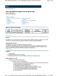
1. The barcode reader is to be mounted on the rear side of the autoloader.
2. Power down the autoloader
3. Remove the SCSI cable(s) and power cord from the rear panel of the autoloader and
disconnect the power cord from the outlet.
4. Remove the cover plate from the rear panel and save the screws. Store the cover plate;
you may use this plate later if you remove the barcode reader.
5. Orient the barcode reader in front of the slot. There is only one correct position. Check to
make sure that the holes align.
6. Connect the cable to the barcode controller outlet.
7. Attach the barcode reader with the screws you saved.
8. Reconnect the SCSI cables and power cord to the autoloader.
3
LTO Autoloader Barcode Reader
Using the Barcode Reader
The barcode reader is controlled through the host software. There is no user interaction, and the
Operator Panel does not indicate that a barcode reader has been added. When you next power
up the autoloader, the barcode reader is automatically enabled for scanning.
Barcode labels
The barcode reader can only operate if barcode labels are present on the tape cartridges. Make
sure that only labels complying with the appropriate barcode label specification are used (see
section below).
Removing the Barcode Reader
1. Power down the autoloader
2. Remove the SCSI cable(s) and power cable from the rear panel. Then disconnect the
power cable from the outlet.
3. Remove the screws that attach the barcode reader to the rear panel.
4. Unplug the barcode reader connector from the controller outlet.
5. Replace the cover plate on the rear panel.
4
LTO Autoloader Barcode Reader
Bar Code Label Specification
For LTO Ultrium 1 Cartridges
About this Specification
This document defines format and contents of the external barcode label to be used on LTO
cartridges. The specifications are defined to both standardize labels and allow users the option
of purchasing or printing their own labels. This specification contains the following information
about the bar code labels:
! Symbology
! Bar code characters
! Encodations
! Quiet zone
! Optical specification
! Label dimensions
! Volume identifier formats
! Reading area
! Label Orientation on Cartridge
Symbology
The LTO Ultrium cartridge label uses the bar code symbology of USS-39. A description and
definition of this symbology is available from the Automatic Identification Manufacturers (AIM)
specification Uniform Symbol Specification (USS-39) and the ANSI MH10.8M-1993 ANSI
Barcode specification.
Bar Code Characters
The bar code string consists of a start character, eight alphanumeric characters, and the stop
character. Quiet zones precede and follow the start and stop characters. The first six characters
may be any combination of upper case A through Z or 0 through 9 (for example, ABC123) to
identify the cartridge volume. The last two characters are determined by the LTO Ultrium
cartridge media type (for example “L” for LTO Ultrium and “1” for tape cartridge generation or
drive manufacturer-unique identifier).
Only upper case alpha A through Z or numeric 0 through 9 characters are allowed.
Human readable characters may be used, provided there is not a conflict or interference with the
automation code. The user specifies the format, colors, and location of the human readable
characters.
Encodation
Refer to the AIM Uniform Symbol USS-39 specification for the description and format of the start
character, identifier characters, and stop character.
Quiet Zone
The quiet zones are the areas preceding the start and after the stop characters. They are clear
of any printing or reflective properties that could cause spurious reflections. The quiet zones are
further defined in the AIM Uniform Symbol USS-39 specification.
5
LTO Autoloader Barcode Reader
Optical Specification
The optical specifications for the bar code labels are listed below.
! Use the white calibration standard to calibrate the print contrast of the Mcbeth PCMII. Be
sure the filter select switch is on position A for all calibration and measurements.
! The reflectivity of the white background (RW) is the reflectivity measured in the center of
narrow spaces using the Mcbeth PCMII print contrast meter. The RW must be between
70% and 85%. At this measurement, isolated print defects and edge roughness are
avoided.
! A spot is defined as an area anywhere within the white background in which the
reflectivity is less than 65%. Spots may not be greater than 0.004 inches (0.102 mm)
enclosed diameter. There may be no more than five spots in the bar code area per label.
Spots may not be any closer to each other than 0.01 inches (0.254 mm).
! The reflectivity of the black areas (RB) may be measured anywhere within any black
area on the bar code. The print contrast signal (PCS) is defined as (RW-RB)/RW and is
measured using the Mcbeth PCMII print contrast meter. PCS must be a minimum of
0.85. Using the PCS measurement will avoid isolated print defects and edge roughness.
! A void is an area within a black area where the PCS is less than 0.85. No voids may be
greater than 0.004 inches (0.102 mm) enclosed diameter. There may be no more than
five voids in the bar code area per label. Voids may not be any closer to each other than
0.01 inches (0.254 mm).
Note: For additional optical requirements and measurement techniques, refer to the AIM Uniform
Symbol USS-39 specification.
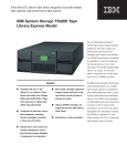
Label Dimensions
The following figure shows the bar code label dimensions.
Note: Dimensions are given in inches with millimeters in parentheses.
Character orientation: horizontal (recommended)
Barcode orientation:
bottom
Recommended supplier: EDP/Colorflex
6
LTO Autoloader Barcode Reader
The following table lists the bar code label dimension specifications.
Specification
Symbol height
Wide to narrow ratio
Narrow element width
Nominal width of wide
spaces and bars
Inter character gap
Bar code element width
maximum
Quiet zone at the beginning and
end of printed bar code string
Total bar code string length,
including quiet zones
Bar code string direction
Edge roughnessa
Tolerances
Dimension
0.44 inches (11.1 mm) minimum as
measured to the inside of the edge
roughnessa
1:2.75
0.017 inches + 0.001/–0.003 inches
(0.432 mm + 0.03/–0.076 mm)
0.047 inches (1.188 mm)
0.017 inches + 0.001/–0.003 inches
(0.432 mm + 0.03/–0.076 mm)
Measured to the outside of the edge
roughnessa. Space width is then the
distance between bar maxima.
10× narrow width = 0.17 inches (4.32mm)
Nominal 2.917 inches (74.088 mm)
May be printed in either direction on the
label but must begin/end with a valid
start/stop character (!)
0.0015 inches (0.038 mm) maximum
0.XXX± 0.005 inches, 0.XX± .0.03
inches)
(0.XXX± 0.127 mm, 0.XX± 0.762 mm)
Less than ± 0.0015 inches (0.0381 mm)
Variation between all wide
bars, white and black
Variation between all narrow bars, Less than ± 0.0015 inches (0.0381 mm)
white and black
Print side
Print the bar code string on the label so
it is on the side of the label towards the
hub
Label stock dimensions
3.110 x 0.669 inches (79 × 17 mm)b
Minimum length for quiet
Nominal 2.917 inches (74.088 mm)
zones, start-stop and data
characters
Minimum width
No less than 0.059 inches (1.5 mm)
narrower than the cartridge label recess
width
Corner cut
0.059 inches (1.5 mm radius)
a
The edge roughness is defined as the transition encountered as a horizontal line is moved
vertically from all black to all white. The bar code edge is defined as the edge of all printed
area attached to the bar.
b
Must fit within the label recess on the face of the cartridge without curling up on the sides or
ends.
Note: The LTO Ultrium label dimensions are derived using the AIM USS-39 specification.
7
LTO Autoloader Barcode Reader
Volume Identifier Formats
!
!
!
!
!
The volume identifier only uses ASCII characters A through Z (41h-5Ah), 0 through 9
(30h-39h), and the combinations of “CLN” and “DG {space} ” as described below.
The prefix “CLNvnnL1”is reserved for cleaning cartridges. The “v” field is an
alphanumeric field to identify a drive unique cleaning cartridge. The “nn” alphanumeric
field is used to track individual cleaning cartridge activity (for example, usage and life).
When the drive requires cleaning, it will request loading of the unique type cleaner
cartridge.
Diagnostic/Service cartridges use the prefix “DG{ space} vnnL1”. The “v” field is an
alphanumeric field to identify a drive-unique diagnostic cartridge, if required. The “nn”
alphanumeric field identifies a specific diagnostic cartridge volume.
The volume identifier field consists of six left-justified alphanumeric characters as
specified in SCSI-3 Medium Changer Commands (SMC) ANSI NCITS 314-199X.
The media identifier characters “Lg” are controlled characters. The “L” designates the
LTO Ultrium type of cartridge. The next character “g” (alphanumeric) designates the
generation of the LTO Ultrium cartridge.
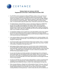
Reading area
Due to mechanical tolerances the barcode reader will read in a defined area with a height of 5,15
mm (see figure below). This area must contain barcode information only and should not contain
any character information.
Label Orientation on Cartridge
8