1
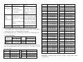
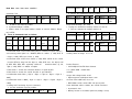
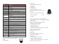
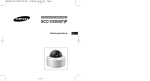
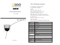
Part 1 Performance Features
4.2”Vandalproof Pan/Tilt Dome Camera
◇
QSZ515D
1/3” SONY CCD + SONY DSP
◇
540TVL
◇
Super wide voltage board: 8-18V
◇
Medium Speed Intelligent Dome PTZ
High transparent vandal-proof dome cover
◇
5-15mm F2.2 2.0MP auto focus lens
◇
User’s Manual
With RS485 remote control, With 128 preset points
◇
360° Horizontal endless rotation, 90° vertical movement
◇
A panoramic view
◇
body rotates flexibly with less noise and
◇
wider view shooting
◇Memory function at accidental power-off (Settings saved)
Technical Specifications:
Model
PDS-320FZA
Image Sensor
1/3"SONY CCD
Digital Signal Processor
SONY DSP
Signal System
PAL
/
NTSC
Scanning System 2:1 Interlace
Scanning Frequency(H)
NTSC:15.734KHZ , PAL:15.625KHZ
Sync. System
Internal
Horizontal System540TVL
Effective Pixels
PAL:795×596
(HxV)
NTSC:811×508
PAL=1/50 ~1/100,000 sec;NTSC=1/60 ~1/100,000
Shuttle Speed
sec
Mini Illumination 0.01 Lux
Rev 120110
S/N Ratio
> 48dB(Auto Gain Off)
Gamma
0.45
Lens
Built-in Decoder
1.3 Megapixel 5-15mm F2.2 2.0MP auto focus lens
1.
Full digital design, all data saved inside of the module with memory
White Balance
Auto
BLC
Open
2.
All in one integrated design, high reliability
Video Output
1.0V P-P,75Ω BNC
3.
128 preset positions can be saved
AGC
Auto
4.
1-80 preset positions support auto cruise function, while 1 cruise route
Power Voltage
Super Wide Voltage (8V~18V)
Input Current
DC12V+/_20% 50/60Hz, 1.2A above
Output Current
12V 800mA
14°F to 122°F (-10°C to 50℃)
Operating Temperature
(relative humidity: up to 95%)
function in case of accidental power loss.
can save 8 preset positions, each position pauses 6 seconds.
5.
Uses RS485 remote control interface
6.
Thanks to its expanding function, any keyboard can operate the controls
of this high speed dome.
Part 2 Functions & Operating Instructions
Storage Temp
-22°F to 158°F (-30°C to 70°C)
This part mainly describes the leading functions and common
Color
White
principles of the all in one intelligent dome camera. It does not
Dimensions(LXD) 5x5 in (125×125mm)
refer to t
he specific operating methods. Different systematical
Weight
2.2 lbs (1KG)(without bracket and adapter)
platforms have different methods. In some cases, special
Address Range
1-256
requirements and operating methods would exist, subject to the
product manual.
Module Index of Variable Speed Pan/Tilt/Zoom:
1.
The control board of the dome has a 10-DIP-switch, used to set
1. Horizontal scanning: 360°rotation
address, communication and control protocols PELCO-D/P (refer to “DIP switch
2. Horizontal speed: 0.5°—50°/s
set”). Any command should agree with the targeted
3. The lowest speed at 0.5°/s, no vibrating images
address, and cameras only response when address code is the
3. Vertical scanning: >90°
4. Vertical speed: 0.5°—30°/s
1. Set CCTV encoding
same.
2. CCTV Camera Operation
2.
Zoom control
5. 128 preset positions (PTZ and vari-focal lens included)
User can adjust the image farther/nearer to get a panoramic view
6. Speed of preset positions: 50°/s
olling the keyboard buttons ZOOM- / ZOOM+ . The speed
7. PTZ scanning precision: ±0.5°
oth digital and optical vari-focus. Digital vari-focus
8. 3X zoom
In the following cases, the camera’s target is unable to auto
Control Protocol:
Focus:
by contr
dome supports b
can be set.
PELCO“P”Protocol
1.
The target is not in the center of the image;
PELCO“D”Protocol
2.
When watching the farther or nearer objects, the objects are not clear;
Baud Rate: 1200b/2400b/4800b/9600b
3.
The target is a strong light, like neon light, spot light etc;
4.
The object moves to fast;
3.
5.
Large square of monotonous object, like a wall;
The speed dome can be set in two fixed locations and scan back
6.
The object is too dark or vague;
h at the set speed. Set #126 for linear scanning. Set #xxx
7. The targeted picture is too small
3. Surveillance function
a) Set & Transfer the preset points
xxx is the scanning speed (1-50 adjustable), after
image would move to the beginning
beginning location, moves the
The function of preset positions is, temporarily storing such
location parameters as horizontal angle / inclination / lens’ focus in
that, move the rod, the
locations. Set #127 as scanning
image to the ending location and set #1
28 as the ending scan
location.
Example 1:Scan setting at the speed of 1s around.
a mem
ory and transferring them whenever they’re needed. User
Setting Method:
can quickly transfer the preset positions via the keyboard, remote
or some
1.
Set #126 preset position.
2.
Set #30 as speed index.
3.
Move the rod and adjust the image as the scanning one.
Automatic Cruise is an internal set function, which inserts the
4.
Set #127 as the beginning location.
points and sets up the automatic cruise among preset positions by
program
5.
Move the rod and adjust the image to the scanning ending location.
and pausing timi
6.
thing else such as PC software. The speed dome
supports 127 preset points.
b) Automatic Cruise
ming them beforehand in the cruise lists. The cruise order
ng can be programmed and one cruise route can
Set #128 as the ending location
Example 2:Scan setting at the speed of 50s around.
store 8 points and time
Setting Method:
s.
c) Auto Scanning
7.
Set #126 preset position.
limits at
8.
Set #50 as speed index.
the left and righ
9.
Move the rod and adjust the image as the scanning one.
Cameras can level scan back and forth among the left & right
the set speed via the keyboard and menu settings using
t limits setup beforehand.
d) Power-off Protection
10. Set #127 as the beginning location.
11. Move the rod
When a planned or unplanned power-off happens, the camera
will automatically preserve the movement state before the
power-off. When the power returns, the camera will auto-recover
2.
the previ
Part 3 Extended Function
Method: Transfer #101 preset position.
3.
This section describes the extended function and common principles
ll in one intelligent dome camera. Different systematical
12. Set #128 as the ending location
Transfer the cruise group
Transfer #101-102 preset point; relatively start #1-2 cruise groups.
ample:Start #1 cruise group.
ous stored movement.
of the a
Start the linear scanning
Transfer #128 preset position.
4.
Start auto-scanning
Transfer #125 preset position or press auto-start button.
360° Auto-scanning back and forth. The speed is fixed internally.
platforms have different methods. In some cases, special
requirements & operational methods could exist, subject to
Part 4 Appendix
systematical manufacturer’s manual.
1.
and fort
preset position,
1. Set the scanning
1.
1. Clearing of fault
For ex
Problem
Possible reason
Solution
No movement and1.Check
ima
the connection of 1.Check the power
ge at power-on
C power input
the soc
connection, make sure
2.Turn off power and
check
ket is
t well
connected
2.Make sure the power outlet is
he transformer
working
Power-on
shows
1. DIP switch setting is incorrect
1. Refer to setup
mage,
2.RS485 interface is not connec
ons, re-set the DIP switches.
but the
controlle
ted or is not
r doesnot work
connected 2.Check
corre
RS485 interface,
ctly
sure the wires are well connect
3.There is a problem with ed
the
Blurred Image
2.
instructi
and in the proper slots
S485 line
3.Refer to the Appendix: RS485
Ball case is dirty
Clean the ball case
2. Setting of DIP Switches
The internal black case has 8 DIP switches. 8,7,6,5,4,3,2,1 are for Addres
s setting, while 10,9 are for Communication Baud Rate.
In the following table, tag “1” for DIP switch “ON”; tag “0” for DIP switch “off”.
a) Setting Baud Rate
Switch #(SW2)
Baud Rate
BIT
Baud
Switch #(SW2)
Rate
BIT
10
9
4
0 0 1 0 0 0 0 0
36
0 0 1 0 0 1 0 0
5
1 0 1 0 0 0 0 0
37
1 0 1 0 0 1 0 0
6
0 1 1 0 0 0 0 0
38
0 1 1 0 0 1 0 0
7
1 1 1 0 0 0 0 0
39
1 1 1 0 0 1 0 0
8
0 0 0 1 0 0 0 0
40
0 0 0 1 0 1 0 0
9
1 0 0 1 0 0 0 0
41
1 0 0 1 0 1 0 0
10
0 1 0 1 0 0 0 0
42
0 1 0 1 0 1 0 0
11
1 1 0 1 0 0 0 0
43
1 1 0 1 0 1 0 0
12
0 0 1 1 0 0 0 0
44
0 0 1 1 0 1 0 0
13
1 0 1 1 0 0 0 0
45
1 0 1 1 0 1 0 0
14
0 1 1 1 0 0 0 0
46
0 1 1 1 0 1 0 0
15
1 1 1 1 0 0 0 0
47
1 1 1 1 0 1 0 0
16
0 0 0 0 1 0 0 0
48
0 0 0 0 1 1 0 0
17
1 0 0 0 1 0 0 0
49
1 0 0 0 1 1 0 0
18
0 1 0 0 1 0 0 0
50
0 1 0 0 1 1 0 0
19
1 1 0 0 1 0 0 0
51
1 1 0 0 1 1 0 0
20
0 0 1 0 1 0 0 0
52
0 0 1 0 1 1 0 0
21
1 0 1 0 1 0 0 0
53
1 0 1 0 1 1 0 0
22
0 1 1 0 1 0 0 0
54
0 1 1 0 1 1 0 0
23
1 1 1 0 1 0 0 0
55
1 1 1 0 1 1 0 0
24
0 0 0 1 1 0 0 0
56
0 0 0 1 1 1 0 0
10
9
2400bps
0
1
1200bps
1
1
25
1 0 0 1 1 0 0 0
57
1 0 0 1 1 1 0 0
4800bps
1
0
9600bps
0
0
26
0 1 0 1 1 0 0 0
58
0 1 0 1 1 1 0 0
b) b) Setting Address Code
27
1 1 0 1 1 0 0 0
59
1 1 0 1 1 1 0 0
In a system, decoder includes intelligent speed dome camera and common de
28
0 0 1 1 1 0 0 0
60
0 0 1 1 1 1 0 0
coder. No repeating address codes exist. As you see in
29
1 0 1 1 1 0 0 0
61
1 0 1 1 1 1 0 0
30
0 1 1 1 1 0 0 0
62
0 1 1 1 1 1 0 0
········
1 1 1 1 1 1 1 1
the table, “1” for “O
N”, “0” for “OFF”
Address
Address Switch
31
1 1 1 1 1 0 0 0
··
1 2 3 4 5 6 7 8
Code
1 2 3 4 5 6 7 8
32
0 0 0 0 0 1 0 0
255
1
1 0 0 0 0 0 0 0
33
1 0 0 0 0 1 0 0
2
0 1 0 0 0 0 0 0
34
0 1 0 0 0 1 0 0
Part 5 PELCO-D Protocol
Data Form:1 beginning position, 10 pieces for data, 1 ending position, invalid
3
1 1 0 0 0 0 0 0
35
1 1 0 0 0 1 0 0
checking point
Address
Address Switch
Code
(8
8
(
Baud Rate:2400, 4800, 9600, 19200Bit/S
SynchronizedAddress
Byte
Code
00H
Command Form:
( )
03H
00H
Preset
Point
Confirmation
#
Code
Byte 1
b
Byte 2 Byte 3
Byte 4
Byte 5 Byte 6
Synchronized
Address
Byt Command
Cod
Code
Command Code
Data Code
Data
e
e
1
2
Byte 7
Code
Confirmation Cod
1
Byte 1
Byte 2
Byte 3 Byte 4 Byte 5 Byte 6
SynchronizedAddress
Byte
Code
00H
07H
00H
Preset
Byte 7
Point
Confirmation
#
e
Code
1.
All data in the Protocol as REX;
Preset Point # Range:00 - FFH
2.
3.
Synchronized Byte is 0FFH;
Address Code is the logical address number of cameras, Address Range:
1. Turning the command of auxiliary swiches on and off:
01H -0FFH;
3.
Transfer the command of preset positions
Command
0
Turn the command of auxiliary switches on
Byte 1
Form of Command Code as follows:
Bit7
a
( )
Bit6
Bit5
Bit4
Bit3
0
0
Auto Scan
0
Code1
Up
Byte 3
Synchronized Byte
Address Code
00H
Bit2
Bit1
Iris
Iris Open
FocusNear
Left
Byte4
Byte5
Byte 6
09H
00H
Auxiliary Switch
Confirmation
Bit0
Close
Command
Focus Far
ZoomWide
Zoom Tele
Down
Byte 2
#
b
( )
0
Byte 2
Byte 3 Byte 4 Byte 5 Byte 6
SynchronizedAddress
Byte
Code
00H
0BH
00H
Code2
Byte 7
Auxiliary Switch
Confirmation Cod
#
1. Command Code 1: BIT7, BIT6, BIT5, BIT3 is 0 without exception; (BIT4 is
auto-scanning control points 1/0:ON/OFF) BIT2 Iris smaller (1 valid); BIT1 Iri
Code
Turn the command of auxiliary switches off
Byte 1
Right
Byte 7
e
Auxiliary Switch # Range:01 to 10
s larger (1 valid); BIT0 focus nearer (1 valid)
2. Command Code 2: BIT7 focus farther (1 valid); BIT6 & BIT5 for the control
of zoom, BIT6 far away from the object (1 valid), BIT5 near
d); BIT4, BIT3, BIT2, BIT1 separately control the
the object(1 vali
movement down, up, left,
right (1 valid); BIT0 is 0 without exception.
3. Data Code 1 controls the horizontal direction of speed 00-3FH
4. Data Code 2 controls the vertical direction of speed 00-3FH
5. Confirmation Code index [(Byte 2 + Byte 3 + Byte 4 + Byte 5 + Byte 6)/
100H]
6. Confirmation Code = MOD [(Byte 2 + Byte 3 + Byte 4 + Byte5 + Byte 6)
7. Setting and Transferring of preset command:
a
Byte 2
Byte 3 Byte4 Byte5 Byte 6
1/3” SONY CCD + SONY DSP
◇
540TVL
◇
Super wide voltage board: 8-18V
◇
◇High transparent vandalproof dome cover
5-15mm F2.2 2.0MP auto focus lens
◇
360° Horizontal endless rotation, 90° vertical movement
◇
Set the command of preset positions
Byte 1
◇4.2”Vandalproof Pan/Tilt Dome Camera
◇With RS485 remote control, With 128 preset points
/100H]
( )
Product Features:
Byte 7
◇A panoramic view
◇Memory function at accidental power-off (Settings saved)
Technical Parameter:
Product features
Model
PDS-320FZA
1. Mini exquisite design with stable
Image Sensor
1/3"SONY CCD
performance
4.2” DOME cover
Digital Singnal Processor
SONY DSP
Signal System
PAL
/
1.3 mega pixel lens
NTSC
5-15mm F2.2 2.0MP auto focus lens
Scanning System 2:1 Interlace
Auto Focus; with the function of preset posit
Scanning Frequency(H)
NTSC:15.734KHZ , PAL:15.625KHZ
ions in lens
Sync. System
Compatible with PelcoD & PelcoP Protocols
Internal
Horizontal System540TVL
Effective Pixels
PAL:795×596
6. 128 preset positions,
(HxV)
NTSC:811×508
cruise routes
2 auto
PAL=1/50 ~1/100,000 sec;NTSC=1/60 ~1/100,000
Shuttle Speed
7. The lowest speed at 0.5°/s, no vibrating images
sec
8. Built-in protective circuit for forced electricity and lightning
Mini Illumination 0.01 Lux
9. Easy installation
S/N Ratio
> 48dB(Auto Gain Off)
Gamma
0.45
Lens
5-15mm F2.2 2.0MP auto focus lens
2. Horizontal speed: 0.5°—50°/s
White Balance
Auto
3. Vertical scanning: >90°
BLC
Open
4. Vertical speed: 0.5°—30°/s
Video Output
1.0V P-P,75Ω
5. 128 preset positions (PTZ and vari-focal lens included)
AGC
Auto
6. Speed of preset positions: 50°/s
Power Voltage
Super Wide Voltage (8V~18V)
Current
800mA
Module Index of Variable Speed Pan/Tilt/Zoom:
14°F to 122°F (-10 ~ 50℃)
Operating Temperature
humidity: up to 95%)
Color
White
SPECIFICATIONS
NAME:4.2” Medium Speed Dome Intelligent
Camera
Model:QSZ515D
1. Horizontal scanning: 360°rotation
7. PTZ scanning precision: ±0.5°
8. 3X zoom
Electric Index:
(
1. Input Voltage: DC12V+/_20% 50/60Hz
2. Input power:1.2A above
Environment Index:
1. Operational Temperature: -10~45℃
2. Preserve Temperature: -30~70℃
3.
Humidity: Relative humidity 0%~90%, no congealing
Control Protocol (standard solution):
PELCO“P”Protocol
PELCO“D”Protocol
Baud Rate: 1200b/2400b/4800b/9600b