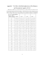
1
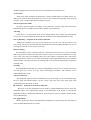
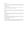
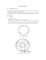
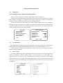
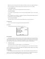
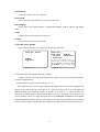
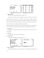
Integrated Intelligent Speed Dome GRAFT User Manual G-SD10X I 1 Safety Instruction These instructions are intended to ensure that user can use the product correctly to avoid danger or property loss. The precaution measure is divided into “Warnings” and “Cautions”: Warnings: Serious injury or death may cause if any of the warnings is neglected. Cautions: Injury or equipment damage may cause if any of the cautions is neglected. Warnings Follow these safeguards Cautions Follow these precautions to prevent serious injury or to prevent potential injury or death. material damage. Warnings 1. In the use of the product, you must be strict compliance with the electrical safety regulations of the nation and region. 2. Please use the power adapter, which is provided by normal company. Please refer to the specific for the requirements. 3. Do not connect several devices to one power adapter as adapter overload may cause over-heat or fire hazard. 4. Please make sure that the plug is firmly connected on the power socket. 5. When the product is installed on wall or ceiling, the device shall be firmly fixed. 6. If smoke, odor or noise rise from the device, turn off the power at once and unplug the power cable, and then please contact the service center. 7. If the product does not work properly, please contact your dealer or the nearest service center. Never attempt to disassemble the camera yourself. (We shall not assume any responsibility for problems caused by unauthorized repair or maintenance. ) Cautions 1. Do not drop the dome or subject it to physical shock, and do not expose it to high electromagnetism radiation. Avoid the equipment installation on vibrations surface or places subject to shock (ignorance can cause equipment damage). 2. Do not place the dome in extremely hot, cold (the operating temperature shall be -20°C ~ +60°C), dusty or damp locations, or fire or electrical shock will occur otherwise. 3. Do not aim the camera at extra bright places (e.g. the sun or the light). A blooming or smear may occur otherwise 2 (which is not a malfunction however), and affecting the endurance of CCD at the same time. 4. The dome cover for indoor use shall be kept from rain and moisture. 5. Exposing the equipment to direct sun light, low ventilation or heat source such as heater or radiator is forbidden (ignorance can cause fire danger). 6. Please use the provided glove when open up the dome cover, avoid direct contact with the dome cover, because the acidic sweat of the fingers may erode the surface coating of the dome cover. 7. Please use a soft and dry cloth when clean inside and outside surfaces of the dome cover, not to use alkaline detergents. 3 Index Integrated Intelligent Speed Dome....................................................................................................1 Chapter 1 Brief Introduction .............................................................................................................1 1.1 Product description ...........................................................................................................1 1.2 Device Appearance ...........................................................................................................2 1.3 Features.............................................................................................................................2 Chapter 2 Installation ........................................................................................................................5 2.1 Installation preparation .....................................................................................................5 2.2 Installation ........................................................................................................................5 2.3 Initial setting .......................................................................................................................7 2.4 Switch setting....................................................................................................................8 2.4.1 Device address setting..................................................................................................8 2.4.2 Baud rate setting...........................................................................................................9 2.4.3 Communication protocol setting ..................................................................................9 2.4.4 Terminal matched resistance settings...........................................................................9 2.5 Alarm In and Output Connection Description.......................................................................9 Chapter 3 Operation Instruction .................................................................................................10 3.1 Power-on Action .............................................................................................................10 3.2 Basic Function Guide......................................................................................................10 3.3 Preset points with specific function: ...............................................................................11 3.4 Onscreen operation guide ...............................................................................................12 Chapter 4 Menu Operation..............................................................................................................13 4.1 Main menu ......................................................................................................................13 4.2 Sys information...............................................................................................................13 4.3 Dome settings .................................................................................................................13 4.3.1 System information setting ........................................................................................14 4.3.2 Camera function.........................................................................................................15 4.3.3 Run Pattern.................................................................................................................16 4.3.4 Line Sync ...................................................................................................................18 4.3.5 Presets ........................................................................................................................18 4.3.6 Patrols ....................................................................................................................20 4.3.7 Pattern Path ................................................................................................................21 4.3.8 Privacy blanking ........................................................................................................22 4.3.9 Alarm Inputs...............................................................................................................23 4.3.10 Clear Settings ...........................................................................................................24 4.4 Restore Defaults..............................................................................................................25 4.5 Camera Reset ..................................................................................................................25 4.6 System Reboot ................................................................................................................26 Chapter 5 Parameters Configuration...............................................................................................27 5.1 Set Parameters through IE...................................................................................................27 5.2 Parameter Configuration through Client Software..............................................................29 Chapter 6 WAN Access...................................................................................................................34 6.1 Dial Up With PPPoE ...........................................................................................................34 4 6.2 WAN Access .......................................................................................................................34 Appendix A Making Network Wire..............................................................................................36 Appendix B RS485 Bus Common Sense .....................................................................................37 Appendix C The Table of the Relationship between Wire Diameter and Transmission Length for 24V AC ...........................................................................................................................................40 Appendix D Wire Gauge Comparison List Home and Abroad .......................................................41 5 Chapter 1 Brief Introduction 1.1 Product description Modern Closed circuit TV System (CCTV) for surveillance is the vision expansion and extension of mankind, and also a necessary part of surveillance system. The development of technologies such as modern electronics, image capture, new material and advanced manufacturing brings more connotations into the front-end camera products for CCTV system, so that its design is more intelligent and friendly. Integrated intelligent high-speed dome is the succession and extension of the integrated design philosophy of PTZ. It is properly designed with many functions, easy to expand and is an outstanding unit representing the camera products of a new generation. With build-in digital decoder and PTZ, this camera is leading the trend of high-tech modern surveillance products. It is of Whole Digital Control and flexible programming; and the sophisticated transmission system has all the functions including preset points, auto scan, cruise, sequence, path preset and also Scan by Frame, Manual Position Limitation, Auto Reverse, Privacy Mask and Back Light Compensation, etc, and achieves Mouse Tracking when connecting to client software and DVR, thus provides Stable, Long-durance Working with hardly any maintenance required. Dome camera supports PELCO-D, PELCO-P and HIK Code protocols, and is Self Adaptive to them. For more convenient usage, the camera supports Menu Setting functions, as parameters like system info, display, camera configuration, pre-set positions, sequence, mask areas can all be set on the menu, while password authentication protect the settings being modified by others. 1 1.2 Device Appearance Figure 1-1 Speed Dome Appearance 1.3 Features Onscreen Menu The dome camera supports onscreen menu function, which allows users to get device information, status, and do dome settings. Self-adaptive to Multiple Protocols The dome camera supports PELCO-D, PELCO-P and HIK protocols, and is self-adaptive to them. Keyboard Control The vertical and horizontal camera movement can be controlled with keyboard, DVR and client software. Manual Stops When the device is controlled by keyboard with this function on, the horizontal motion of camera will be limited within the restricted area, and users can not see the scene outside the area. Auto Scan The speed dome supports three scan modes in horizontal direction including automatic scan, frame scan and random scan. Scan speed can be set on menu from level 1 to 40 corresponding to the range from 1°/second to 40°/second. Auto Scan Stops Depends on the Camera Function The camera can only scan back and forth in the set area and will flip automatically when it reaches the limit with this function on. Users can not see the scene outside the area. Scan limiting function is under manual stopping function, i.e., if manual stopping function is set for device, 2 manual stopping function will become effective automatically at automatic scan. Preset Point Each preset point includes PTZ horizontal, vertical position and lens zooming factors, etc. When preset point is initiated, the dome will move to the position corresponding to preset point message. Users can add, delete and call each preset point. Onscreen Operation Guide Onscreen operation guide can display preset point title, position angle and zoom factor information on screen, and the function can be opened or closed in menu. Auto Flip If the object is on the bottom of the screen during manual scan, camera will automatically reverse 180° to ensure continuous monitoring. The function can be enabled/disabled by menu. Privacy Blanking Depends on the Camera Function With privacy blanking, users can set the screen area not to be seen. The covered area will move along with device in horizontal and vertical directions and automatically adjust its size on zooming to ensure the area is always covered up. Mouse Tracking The speed dome can be controlled with the 2 buttons and scroll of mouse can be used under HIK Code protocols with devices and client software. Click on a certain area and the device will move to the scene with corresponding point as the center. When a rectangular area is selected by left-clicking, device will move to its center and enlarge it. With right-clicking, the lens will zoom in, and the scroller can easily make the lens zooming, and mouse operation automatically incorporates zooming effect. Zooming Vertical and Horizontal scan speed will be changed during zoom time, as speed down if zoom out and speed up if zoom in to get better monitoring performance. The function can be enabled/disabled by menu. Auto focus function The integrated engine will focus automatically to get clear image. Users can manually adjust focus by FAR and NEAR buttons, but the system will enter auto focus mode again after vertical/horizontal movement or zoom. IR Cut Filter Depends on the Camera Function IR can be set as auto illumination convert mode or manual illumination convert mode. The integrated engine will automatically change CCD illumination with regard to environment lightening conditions. Without this function on, users can choose “Day” or “Night” mode to choose color or B/W display. Low Light Shutter Shutter speed slows down in low illumination conditions to keep the image clear. The function can be enabled/disabled in the user menu. 3 BLC Function Object will turn dark like shadows when strong background lighting exists. With BLC function on, it can automatically do back light compensation to avoid object being unidentifiable and get clear images. Automatic White Balance Auto White balance function compensates between different color temperatures to get true color of object and enable the feeling of on spot monitoring. Patrol Support up to 4 patrol path settings. Users use a group of preset positions to guide the camera on the patrol path, scan speed between 2 preset points and dwell time on each point can be set separately. Pattern Path Series of camera movements can be saved and recalled again to form a pattern path. Supported information includes vertical and horizontal PTZ movements, zoom preset, while Auto Focus and Iris is set as default mode. External Alarm The camera supports 6 channels ON/OFF alarm input, input mode can be either N.O. or N.C., or disable this channel. Camera will perform preset operations like scan, cruise, sequence and preset positions calling when detected alarm signals. Auxiliary Alarm Output 2 channels of auxiliary ON/OFF output for trigger or control other devices. When an alarm occurs, it will be output through the mapped auxiliary channel. Output mode can be either NO or NC, or disable this channel via operation menu, and the auxiliary output time can also be set. 4 Chapter 2 Installation 2.1 Installation preparation Please check if all the items on the package list have been included with your camera before installation and make sure they are in good condition. [Notice]: The standard configuration of dome is not including power adapter, the standard of the power adapter is AC24V/3A. And the Network Speed Dome, whose model has an “E” at its end, support PoE power. 2.2 Installation 1. Install the Hugger salver If the wall is wood, use self tapping screw to fix it to the wall. If the wall is concrete, adhere the fix card in the attachment to the position where plan to place the dome. Make 3 Φ5 holes in accordance with the 3 holes on the fix card. Then fix with the concrete screws, then use self tapping screw to fix the Hugger salver, as shown in Figure 2-1 Figure 2-1 install the fix card Figure 2-2 install the hugger salver 5 2. Open the dome cover and then remove the camera and pearl cotton. 3. In the bottom of the camera, we can see device base board as shown in Figure 2-3. There are two dialing switches, SW1 and SW2 for the setting of device address code, baud rate and communication protocol and other parameters. Please refer to “Chapter 2.4 Switch Setting” for specific setting. 1 1 Address and protocol dial-up description 2 3 1 2 3 4 5 6 7 IN OUT GND +12V AI N AOUT GND ALARM 8 9 10 4 A+ BRS485 2 Analog video output interface(BNC) 3 Address and protocol dial-up switches 4 Network Interface 5 Power, voice input/output, alarm input/output and RS485 Interface 5 Figure 2-3 sketch map for speed dome chassis 4. Connect Power wire, Voice input/output wire, Alarm input/output wire, RS-485 control wire, video wire and network wire. Showed as Figure 2-3 “Speed dome chassis sketch map”. The contents of 5th part of the figure are (from left to right): DC 12v socket, voice input/output socket, alarm input/output socket and RS-485 control wire socket. Connection method description Device is provided with green bended-pin plug for signal cable. The wiring procedure is listed as below: 1. Pull out green bended-pin plug on device base board. 2. Loose the screw on the plug with micro-“I” shaped (or crosshead) screw driver and insert the signal cable on the lower edge of spring strip, and fasten the screw. 3. Insert the plug back to the corresponding green bended-pin socket. 4. Connect power cable, video output cable, RS-485 control cable, alarm input/output cable (based on the need), and then close base-plate and fasten back screw. 5. Install the Speed Dome Input the three pillar into the three holes of Hugger salver, pay attention to the directions, make the “I” symbol on the Hugger salver in the same direction of “I” symbol on the speed dome. Turn the speed dome widdershins about 15 degrees until it can’t be turned any further. At this moment, the “I” symbol on the speed dome is aligned with the locking screw on the 6 Hugger salver Screw the locking screws Figure 2-4 Install the speed dome Figure 2-5 the speed dome be installed 2.3 Initial setting Address: 0 Baud rate: 2400 120Ω matching resistance: OFF 7 2.4 Switch setting Figure 2-6 Address and protocol dial-up switches There is a dial-up switches on the speed dome chassis, showed in Figure 2-6. Bit 1 to Bit 5 are used to set the speed dome address, Bit 6 and Bit 7 are used to set the baud rate, Bit 8 and Bit 9 are used to set parity and Manchester protocol. Bit 10 is used to set 120Ω matched resistance. The set method is stated as below in detail. Note: This speed dome auto adapt Pelco-P、Pelco-D and HIK Code protocol. 2.4.1 Device address setting 1 to 5 is used to set device address as follow, 1 is the smallest and 5 is the biggest: Device address 0 1 31 1 2 3 4 5 OF OF OF OF OF F F F F F OF OF OF OF ON F F F F ON ON ON ON ON More examples for address codes dialing mode (1-31): address 0 1 2 3 4 5 6 7 8 9 10 11 12 1 OFF ON OFF ON OFF ON OFF ON OFF ON OFF ON OFF Code dialing 2 3 4 OFF OFF OFF OFF OFF OFF ON OFF OFF ON OFF OFF OFF ON OFF OFF ON OFF ON ON OFF ON ON OFF OFF OFF ON OFF OFF ON ON OFF ON ON OFF ON OFF ON ON 8 5 OFF OFF OFF OFF OFF OFF OFF OFF OFF OFF OFF OFF OFF 13 14 15 16 17 18 19 20 21 22 23 24 25 26 27 28 29 30 31 ON OFF ON OFF ON OFF ON OFF ON OFF ON OFF ON OFF ON OFF ON OFF ON OFF ON ON OFF OFF ON ON OFF OFF ON ON OFF OFF ON ON OFF OFF ON ON ON ON ON OFF OFF OFF OFF ON ON ON ON OFF OFF OFF OFF ON ON ON ON ON ON ON OFF OFF OFF OFF OFF OFF OFF OFF ON ON ON ON ON ON ON ON OFF OFF OFF ON ON ON ON ON ON ON ON ON ON ON ON ON ON ON ON 2.4.2 Baud rate setting Dial-up switches 6 and 7 are used for setting baud rating, from 00 to 11. They represents 2400bps、4800bps、9600bps、19200bps respectively. If the value is beyond the range, the default baud rate is 9600bps. The following table shows the dial-up way of corresponding baud rate in detail: Baud rate 2400 4800 9600 19200 6 OFF ON OFF ON 7 OFF OFF ON ON 2.4.3 Communication protocol setting Dial-up switches 6 and 7 are used for setting parity and Manchester protocol. The following table shows the dial-up way of corresponding communication protocol in detail: parity/non e /even /odd Manchester 8 9 OFF OFF ON OFF ON OFF ON ON 2.4.4 Terminal matched resistance settings Turn the Bit 10 of dial –up switches on means getting through 120Ω RS-485 line terminal matched resistance, on the contrary, means don’t get through the resistance. 2.5 Alarm In and Output Connection Description The speed dome can connect one channel alarm semaphore (0 to DC 12v) input and one channel on-off output. Thereinto, the connection of alarm output is showed below. 9 Alarm output belongs to switching value(no voltage), external power is needed when connect with a annunciator. When connect with external DC power(the connection method is showed in left diagram), the external power should be in the range of DC12V, 30mA. When connect the external AC power, external relay is asked to avoid the danger of device damaging and getting an electric shock (the connection method is showed in right diagram). Chapter 3 3.1 Operation Instruction Power-on Action After power is turned on, device will perform self-test action that begins with lens motion, then horizontal motion and finally vertical motion. After power-on self-test action, the interface as shown in following Figure will be displayed. The start-up interface will disappear after 40 seconds. SYSTEM INFORMATION DOME DRIVER MODEL SEE THE DOME 0 DOME ADDRESS COMMUNICATION 9600,N,8,1 35oC TEMPERATURE SOFTWARE VERSION 2.0 ENGLISH LANGUAGE IP ADDRESS: 192 000 000 064 SUB MASK: 255 255 255 000 BACK EXIT Lens motion: Lens zoom in and out, and then close iris. Iris keeps closed until motor action finishes. Horizontal motion: Dome turns clockwise first and then counter-clockwise after it detects zero position. It will stop after a short trip. Vertical motion: camera will begin with slow downward motion. After reaching contact point, it will move up quickly and stop at 45o. Column “Dome Address” displays current device address, i.e., address on dial tray. Now, dome soft address is not used. If dome soft address is used, dome soft address will be displayed on booting. Please refer to Chapter 4.3.1 for dome soft address settings. 3.2 Basic Function Guide The following operation shall be done in collaboration with backline control device or client software. Control devices include control keyboard and DVR, etc. Client software is the software 10 on customer’s end. Examples are given here for common operation only with assumption that the current control system supports following operation. Please refer to Client Softwatre User Manual for detail operation guide. Horizontal and vertical motion: move the joystick toward the expected direction, or press Up/Down/Left/Right buttons. Lens zooming operation: press TELE button to pull the lens closer and the scene will be bigger. Press WIDE button to pull the lens farther and the scene will be smaller. Focusing operation: After FAR button is pressed, the object far away will become more legible and the object in vicinity will become ambiguous. After NEAR button is pressed, the object in vicinity will become more legible and the object far away will become ambiguous. Under auto focus mode, camera will focus automatically to maintain legible Figure. Now, manual focusing operation will still be possible. However, after other operation of device, camera will resume auto focus. Iris operation: press OPEN and the iris will enlarge and image brightness will increase. Press CLOSE and the iris will gradually shrink that leads to brightness decrease. Under automatic iris mode, both OPEN and CLOSE buttons are still valid. However, after other operation on dome, camera will resume automatic iris motion. Preset point operation: Preset point can be set or called through keyboard or menu. Under manual operation mode, press PRESET + numeric in sequence and then ENTER to confirm and save the current PTZ and lens setting as preset point information. Preset point num is the input numeric. And it supports 200 preset points. However, preset point setting range is related to control system used. See control system manual. To utilize preset point, press CALL + numeric in sequence and ENTER to confirm. Part of preset point codes are used as special function and saved for operation. See 3.3 on page 35. For preset point operation on menu, see 4.3.5 on page 48. Note: Utilization of preset point on device will be restricted within joystick range. If preset point is in the range, the utilization is effective. If not, it will be ignored. Special preset point utilization is no exception. 3.3 Preset points with specific function: Examples of special function preset point are given as follow: No. of preset point function 33 auto flip 34 return to zero point 35 run patrol path 1 36 run patrol path 2 37 run patrol path 3 38 run patrol path 4 11 39 camera setting to day working mode 40 camera setting to night working mode 41 run Pattern Path 1 42 run Pattern Path 2 43 run Pattern Path 3 44 run Pattern Path 4 92 Limit Stops setting 93 setting of manual left-right stops 94 remote reboot 95 enter main menu 96 stop scan 97 random scan 98 scan by frame 99 auto scan 3.4 Onscreen operation guide Device provides a series of onscreen operation guide to facilitate operation. The characters that can be displayed include lens zooming rate, angle, alarm, clock and preset point title. Len zooming rate indication: In form of Z XXX, and XXX is the current zooming rate of lens. Angle position: In form of PXXX/TXX, the three digits after P is horizontal angle and the two digits after T is vertical angle. The angle of Zero position can be defined by user on menu or defaulted by the system. For example: P235/T35 displayed on screen indicates that the current device is at a position of 235 ° of horizontal angle and 35 ° of vertical angle. Alarm: when an alarm is triggered, screen will display relevant alarm number and a horn-shaped pattern in front alarm number. If alarm is triggered in several channels, the number of alarm triggered will flash. Clock display: in form of X day、X month、XXXX year week-day X 、XX second. Hour is displayed with 24 hour system. Preset point label display: utilized preset point label is displayed. 12 XX hour、XX minute Chapter 4 Menu Operation 4.1 Main menu [Notice]: Different types of Dome with a different menu. Enter no. 95 preset point to enter device Main menu as shown in Figure 4-1. Change cursor position through joystick and move the cursor on the menu option to be selected. Press <OPEN> to confirm, i.e., operation can be done on this menu options. If current menu contains sub-menu, and then it will enter the corresponding sub-menu. To perform operation on menu option, the selection number behind menu can be changed by moving joystick up and down. Press <OPEN> to confirm and return to previous menu. The same procedure is followed for the next operation for which no description is given. Select “Exit” menu option to confirm and exit from menu operation. Figure 4-1 4.2 Figure 4-2 Sys information This menu displays current dome system information, as shown in Figure 4-2. Information in menu option can not be changed and Temperature refers to temperature inside device cover. Click “Return” to return to the previous menu, or click “Exit” to save the settings. Operation is similar to all level submenus. 4.3 Dome settings On entering dome settings menu, information as shown in Figure 4-3-1 is displayed. There are totally two interfaces for dome settings menu, as shown in Figure 4-3-1 and Figure 4-3-2 respectively. The two interfaces can be switched over by moving joystick left or right. During interface switch-over, cursor shape can be changed from time to time to indicate the interface status (first page, end page and middle page). The controlled items are selected still by moving joystick up and down. Figure 4-3-1 Figure 4-3-2 13 4.3.1 System information setting System information setting menu is shown in Figure 4-3-3. 1 Device soft address: When soft address is enabled, device will apply soft address. This unit supports 1~255 device soft addresses. However, consideration shall be given on the supporting range of currently applied keyboard for device address when soft address is set. When soft address is disabled, device will apply the hard address on dialing code on the base board. Among these addresses, the hardware address 0 is the broadcasting address which can receive control message from any address. If control device address is zero, all devices can be brought under control. Figure 4-3-3 Figure 4-3-4 2 System date: System date interface is shown in Figure 4-3-4. The interface in Figure indicates that the current date is 15 hr 33 m 25 s, Jan. 18, 2007. Menu options to be modified are selected by moving joystick left or right. 3 Zero position angle setting: After entering this menu, move joystick left or right to define the zero position angle of device in horizontal level. Save the setting and exit after selection. 4 Display information setting: Display information setting menu interface is shown in Figure 4-3-5. The display duration can be selected independently with each menu option. The display time interval can be 2 seconds, 5 seconds or 10 seconds. Normal open mode or close mode can be selected as well. Each display position is fixed and preset point display position covers position angle display and lens zooming rate display. If both are set on Normal open mode, preset point title will always be displayed under preset point mode. Under the other modes, the position angle and lens zooming rate will be displayed. Alarm prompt and menu operation can be done at the same time. The difference is that alarm linkage will be triggered under non-menu mode, while no alarm linkage will be triggered under menu mode. 14 Figure 4-3-5 Figure 4-3-7 Figure 4-3-6 Figure 4-3-8 4.3.2 Camera function Camera function menu has two interfaces, as shown in Figure 4-3-6, 4-3-7 and 4-3-8. When it is not on menu option operation mode, three interfaces can be switched over by moving joystick left or right. 1 Auto focus: Under auto focus mode, camera will automatically adjust the focus to get clear image, and the manual FAR and NEAR focus adjustment buttons will be disabled with this function on. When no auto focus is used, focusing shall be done manually. 2 Zoom Limit: This unit has zooming options 18, 36, 72, 144 and 216. Max. optic focus variation is 18 times. 3 Zooming Speed: Zooming variation speed comes in three positions, i.e., high, medium and low. 4 Low lighting Limit: The shutter will automatically slow down to obtain clearer figure through exposure time extension under low lightening. 5 IR Cut Filter: IR Cut Filter can be set into both auto and manual mode. The camera will automatically convert CCD sensitivity according to ambient light change. If the function is disabled, color display or black & white display can be selected through “Day” and “Night” on the menu. 6 Sharpness: Options are from 1 to 16 and 16 is the most legible position. 7 Backlight Comp When backlight compensation is on, camera will automatically compensate the brightness of dark object on the background that is under strong light, and adjust bright background, in order to avoid light conglomeration on the entire figure due to bright background and unidentifiable dark object. Thus, legible Figure can be obtained. 8 Expo Pattern Exposure pattern can be set to one of auto mode, iris, shutter preference and self-defined mode. When setting is automatic, iris, shutter and gain will all be automatic. When it is set to iris preference, the iris will take setting value, while shutter and gain will be automatic. When it is set to shutter preference, the iris will take setting value, while iris and gain will be automatic. When it is set to self-definition, the iris, shutter and gain will all take their setting values. 15 9. Iris Iris can be set from 0 to 17. 17 is the biggest iris. The bigger the iris is, the brighter the image will be. 10 Shutter Shutter can be set into 1, 2, 4, 8, 15, 30, 60, 125, 180, 250, 500, 1000, 2000, 4000 or 10000. If it is set to X, the shutter time is 1/X. 11 Gain Gain can be set from 0 to 15. The bigger the gain is, the brighter the Figure will be. 12 Expo Comp Exposure compensation effect can be adjusted through exposure volume adjustment. 13 White Balance The color temperature gap is extremely big with different lights. Whiteness balance correction will compensate different color temperature, and thus the true color of the object can be restored. This unit has four modes: auto, indoor, outdoor and user mode. When it is on user mode, “Red” and “Blue” color compensation options will be enabled. 4.3.3 Run Pattern Run pattern menu has two interfaces as shown in Figure 4-3-9 and Figure 4-3-10. If menu options are not selected on interface 1, it can enter interface 2 by moving joystick to the right. Likewise, if menu options are not selected on interface 2, it can enter interface 1 by moving joystick to the left. MOTION ENABLE LIMIT STOPS <SET MANUAL STOP> <CLEAR MANUAL STOP> <SET SCAN STOP> <CLEAR SCAN STOP> MOVING SPEED LEVEL MIDDLE PRESET SPEED LEVEL BACK Figure 4-3-9 4 EXIT Figure 4-3-10 1 Auto Flip If the object is on the bottom of the screen during manual scan, camera will automatically reverse 180° to ensure continuous monitoring. If joystick is not released during this period and keeps moving up (i.e., the device will run in the direction in which vertical angle increases), then the dome will run in the direction in which the vertical angle reduces after flipping to keep tracing continuity. After joystick is released, order resolution will restore to its original status. When auto flip is disabled, vertical motion of dome will not trigger horizontal motion. Note: The function will be invalid when pattern path is set. If the dome is still in limitation area after turning over by more than 180 °, then the function will be enabled. Otherwise the function will be invalid. 16 2 Proportional Pan: When proportional pan function is started, PTZ horizontal and vertical motion speeds will automatically change accordingly. When portion increases, camera motion will automatically slowed down; when portion decreases, camera will automatically speed up in order to achieve better object tracing effect. If this function is closed, it will be difficult to trace slow motion object or focus on still object with higher proportion. Note: this function will always be valid on setting pattern path. 3 Park Time When no control signal is received within a period of time and park action is set, then the dome will perform this motion. Park time can be set from 5 seconds to 720 seconds. Note: If no control signal is received for a period of time under following circumstances, no automatic running will be performed: 1. Call special preset point and relative motion isn’t stopped; 2. External alarm with motion unstopped. 4 Park Action The option includes three scan modes as auto scan, scan by frame and random scan with 4 patrol path, 4 pattern path and 8 preset points. Automatic running mode can also be set into closed mode. 5 Scan speed It is the speeds for automatic scan, frame scan and random scan, which can be set from 1 to 40 corresponding to device horizontal speed from 1 °/s to 40 °/s. Due to the speed-up and slow-down of dome running, if scan area is small with high scan speed and scan stops settings, the scan may have already slowed down before reaching the preset speed and therefore it can not reach the scan speed. 6 Preset Pic Freeze: When preset point is called with this function on, video image will keep the previous status before the dome reaches the target preset position. 7 Limit Stops: Left and right limits can be set for both joystick operation and scan to let the dome runs in a certain ranged area. This limit on device will be valid only when limit stops is open. If limit stops is set to close mode, then the dome will not be restricted even if there is stops setting. 8 Manual stops: To set the operation limit of joystick, enter this menu option and move the joystick to the left or right to the desired limited area based on the prompt. Move the joystick to the right after pressing <OPEN> to confirm. After it reaches the desired limited area on the right, press <OPEN> to confirm and the setting is finished. If “Limit Setting” menu option is on Open status, device will move the joystick to the left and the boundary reached is the left limit point. 17 When device moves the joystick to the right, the boundary reached is the right limit point. If there has already been a limit stop setting, the new setting will cover previous setting. 9 Clear manual stops This option is used to clear the operation limit of joystick already set. 10 Auto Scan Stops It is used for setting limit stops in auto scan mode. Setting method is same as the joystick operation. Note: If manual stops are already set, automatic scan will be restricted within manual stops area no matter there is a auto stop setting or not. 11 Clear Auto Scan Stops: This menu option is used to clear the operation limit stops of joystick already set. 4.3.4 Line Sync Note: Version 2.00 does not support line synchronization function. 4.3.5 Presets Preset point menu interface is shown as Figure 4-3-11. Figure 4-3-11 Preset Number The dome supports up to 200 preset points. “Preset Number” displays the preset point under the current operation. If this preset point has already been defined, the description of this preset point will be displayed below. If it is not defined, “No Definition” will be displayed. Preset points for special application will remain in control protocol and do not display in setting therefore. 1 Edit Preset Label Preset label settings is as shown in Figure 4-3-12 (in editing status). The label input can be numeric, capital or small English letter, special symbol or the Chinese character contained in Level-I Chinese Word Bank. The inputting method contains simple editing function with the following function keys: ZOOMWIDE For switching between input status INS or OVR, where INS indicates that input characters are inserted to cursor position and OVR indicates that input character will displace the character at cursor position. Cursor will automatically move forward after character is input. 18 ZOOMTELE Delete the characters at cursor position. FOCUSFAR Move the cursor under the title in cycle from right to left. FOCUSNEAR Switch input status among Numeric, Capital/Small English, Symbol, Chinese and Editing status. OPEN Confirm/enter into the operation of next level. CLOSE Cancel/return to the previous operation. UP, DOWN, LEFT, RIGHT Select Chinese character to be input/move cursor/input phonetics. Figure 4-3-12 Figure 4-3-13 Description is given through the following examples: 1) Input of numeric, capital & small English letter and special symbol is described through the example of English letters. Small English letter input is shown in Figure 4-3-13. Select input status for Small English with FOCUS NEAR, and the fist 10 letter in English will display on the menu. If the letter to be input is “b”, please move the cursor to “b” with LEFT and RIGHT and then press OPEN to confirm. If the letter to be input is “k”, please switch to the following 10 English letters with UP and DOWN, so that they will display in the bracket, and operate similarly as letter “b” input (during this period, ZOOMWIDE, ZOOMTELE, FOCUSFAR and FOCUSNEAR will all be effective). On finishing letter input, press CLOSE to return to editing mode., and press OPEN to finish input. The modifications will be cancelled if CLOSE is pressed. 19 Figure 4-3-14 2 Reference Info (Lens Position) After entering this menu, users can operate PTZ and lens to set the position of current preset. If the position on this preset point has already been set, the original setting will be covered. Note: the lens position setting will be restricted within the limited area when manual stops are set. 3 Camera Func There are three interfaces on Camera Function sub-menu in Presets menu, as shown in Figure 4-3-14, 4-3-15 and 4-3-16. Camera function can be set separately for each preset point, and the setting is valid on preset point mode only. After preset point status is changed, the camera function parameters will automatically restore to default settings. Figure 4-3-15 4 Figure 4-3-16 Clear Presets This menu item is used to delete current preset point. 4.3.6 Patrols See Figure 4-3-17 for patrol menu interface. 1 Patrol Num It is the number of patrol path for the current operation. This unit supports 4 patrol paths numbered from 1 to 4. 20 Figure 4-3-17 2 Figure 4-3-18 Edit Patrol Path Menu interface of edit patrol path is shown in Figure 4-3-18. Move joystick up and down to select the numbers in “Number” column. Move the joystick to left and right to select between “Preset”, “Dwell Time” and “Scan Speed”. When cursor stays on “Preset”, “Dwell Time” and “Scan Speed”, move the joystick up and down to change setting value. Presets can be deleted or added in the edited path. “Preset Point” is initialized as 0, “Stay Time” as 2 and “Cruise Speed” as 30. Click Open and exit after finish setting. Note: Patrol begins in horizontal direction. After horizontal scan is finished, it will quickly reach the vertical preset position, followed by a pause and then corresponding lens zooming change. 3 Preview Path Users can view the patrol path already been set under this function, and stop preview on clicking OPEN. 4 Clear Path This menu option is used to delete current patrol path. 4.3.7 Pattern Path Pattern Path menu interface is shown in Figure 4-3-19. Figure 4-3-19 Figure 4-3-20 1 Pattern Path Num It is the Pattern Path number for the current operation. This unit supports 4 Pattern Paths from 1 to 4. 21 2 Program Path The submenu of program path is shown in Figure 4-3-20. Enter this option by pressing Enter button and the following operation on dome will be recorded. The current available space will be display lively, and the path can no longer be recorded after the remaining space is 0. Note: Among the four paths, path 1 has the highest priority and path 4 the lowest. To edit a certain path when another edited path with lower priority already exists or this path has already been edited, then the system will indicate whether the previous editing shall be deleted or re-editing is required, which can be done by following the prompt message. If no manual stops are set and this stops are set in the following operation, this stops will act on the motion recorded in the Pattern Path. 3 Preview Path If the Pattern Path corresponding to the current path has been set after this menu option is entered, this Pattern Path shall be run for preview. After Exit is entered, the Pattern Path will stop running. 4. Clear Path This menu option is used to delete the current patrol path. Note: when a path is deleted, the other paths already edited with lower priority will be deleted at the same time. 4.3.8 Privacy blanking The menu interface for privacy cover-up is shown in Figure 4-3-21. 1 Window Num It is the window numbers for available operation from 1 to 12. Up to 8 windows can be set on one image. 2 Window Status Window status can be set as Open or Close. If current window has not been set, users cannot set it as Open. After Set Window, the default window status will be Open. Figure 4-3-21 3 Figure 4-3-22 Set Window Set Window is shown in Figure 4-3-22. Press OPEN to enter Set Window interface and the 22 monitor will display a semi-transparent purple blanking at the center. Now, the setting is “Adjust Position”. The masked area can be moved to video center by moving joystick up and down or to the right or left. Then, press NEAR to change the setting to “Adjust Size”. The size of masked blanking can be adjusted by joystick. Press OPEN to save masked window settings after adjustment. At the same time, window color will change to non-transparent gray. The setting information can be switched for multiple times. If the window has already been set before entering this interface, the system will indicate whether to re-setting or not, and users can follow the prompt operation guide afterward. 4 Clear window This setting is used to delete the blank window with the current number. 4.3.9 Alarm Inputs Alarm Inputs menu is shown as Figure 4-3-23. 1 Alarm Resume This function can be set as Open or Close. When an alarm is triggered, the dome will perform the preset operation. If alarm resume is open after the alarm is eliminated, the dome will return to the status before the alarm is triggered. If alarm resume is closed, the dome will stop the current movement only and not return to the status before the alarm triggered. Note: 1. Pre-alarm status includes PTZ position, lens zooming factor, focus and iris parameters before an alarm is triggered. 2. If the dome is in motion before an alarm triggered, it will return to previous PTZ position and then continue with the motion before the alarm is triggered. Figure 4-3-23 Figure 4-3-24 2 Alarm Sequence If there are more than one channel with highest priority among the alarm channels currently triggered, then the dome can do all the preset operations following the time reference between the alarms, and the time interval can be set from 1 second to 200 seconds. 3 Alarm Rest Delay After the alarm for one channel is eliminated, the alarm of this path will not be triggered for a certain period of time in order to avoid duplication. This time interval can be set from 0 second to 300 second. 4 Alarm Settings Alarm settings menu is shown in Figure 4-3-24. (1) Alarm Num Num 1 to 6 refers to the alarm channel num. 23 (2) Priority Alarms priority is divided into three priority levels as high, medium and low. If alarms triggered are at different priority levels, only the linkage corresponding to the highest priority alarm will be performed. If there is more than one alarm with the highest priority, the current alarm act will be switched automatically among them in every alarm sequence time. (3) Alarm Act One Alarm Act can be set for each alarm input channel. When an alarm is triggered, this action can be performed automatically. The alarm act can be set in preset point 1~8, patrol 1~4 or Pattern Path 1~4. If no response action is needed, it can be set to “NONE”. (4) Aux Output The dome has 2 auxiliary outputs and each alarm channel can be related with one channel output. If it is set to “1”, then the alarm channel will be referring to auxiliary output 1. If it is set to “2”, then the alarm channel will be referring to auxiliary output 2. Set to “NONE” if no auxiliary output is needed. (5) Alarm Inputs It is used for defining alarm input signal type and can be set to NO, NC and Off. With Normal Close, the low-electric-level alarm will be triggered. With Normal Open, the high-electric-level alarm will be triggered. With Off, this path of alarm will be closed. 5 Aux Output Auxiliary output menu is shown in Figure 4-3-25. (1) Aux Output It is used to set auxiliary output type to Normal Open or Normal Close. With Normal Open, output 1 is valid. With Normal Close, output 0 is valid. (2) Dwell time It refers to output interval on this output channel, which can be set from 0 to 60 sec. Figure 4-3-25 Figure 4-3-26 4.3.10 Clear Settings Clear Settings menu is shown in Figure 4-3-26 and used to clear dome settings. Note: Please pay attention with “Restore Defaults” as all users’ settings will be cleared and the dome will automatically reboot. 24 4.3.11 Password protection Note: Version 1.00 does not support this function. 4.4 Restore Defaults “Restore Defaults” menu is shown as Figure 4-3-26. The dome will be restored to below default parameters this operation is taken. Device address 0 CommSpeed 9600bps 120Ω matching resistance closed Dome Soft Address closed Azimuth Zero Display Horizontal benchmark Auto Focus Open Zoom Limit Optics Zoom Zoom speed high Low Light Limit Open IR Cut Filter Automatic Backlight Comp Closed Expo Pattern Automatic Exposure Comp 0dB White Balance Automatic Auto Flip Open Proportion Pan Open Park Time 5 seconds Park Action None Scan speed 28 °/second Preset Pic Freeze Close Limit Stops Close Alarm Resume Open Alarm switchover time 5 second Effective Sequence 5 second Alarm Inputs Close Aux Output 1 and 2 NC Aux Output 1 and 2 Dwell Time 0 second Alarm Display, Clock Display Open Zoom display, Reference Info, Display for 2 seconds after Preset Label display 4.5 restore Camera Reset It is used to reset the camera, and camera parameters will be restored to factory settings and 25 the camera will reboot. 4.6 System Reboot It is for system rebooting. 26 Chapter 5 Parameters Configuration [Notice]: This chapter is just for network dome. There are several network parameters of the camera that need to be set after the hardware installation. Those parameters including IP address, subnet mask and port number, etc. can be set through various kinds of methods, 2 of which are introduced as below. 1. Set the camera parameters such as IP address and PPPOE through IE. 2. Set the camera parameters through the client software. Please make sure that the PC and network dome are connected and can ping successfully before the parameter setting. 2 different ways of connections are showed as Fig. 5.1 & Fig. 5.2. Fig 5.1 Direct Line Connection Fig 5.2 Cross Line Connection 5.1 Set Parameters through IE The default IP of the dome is 192.0.0.64 with 8000 as the default port, admin as the administrator, and 12345 as the password. The administrator can create up to 15 separate operators with different right levels. To login the dome through IE, input the IP address in the address column, and the “Login” dialog box will pop-up as Fig. 5.3. Input your user name and password, and then click “Login” to enter the “preview” page. Double click the “Camera 01” channel or “Preview” button to view the menu as Figure 5.4. Right click the “Camera 01” channel, and the “Main Stream”、“Sub Stream” and “Open sound” options will popup. Select the Open sound option. Fig 5.3 Login Interface 27 Fig 5.4 Previewing Interface The “Playback” and “Log” functions are reserved as Fig. 5.4. To set the dome parameters through IE browser, click “Config” and wait for the “Remote Parameters Config” dialog box to pop up, and then set the parameters like IP address, etc. for your demand as Fig. 5.5. For more specific information of “Remote Parameters Config”, please refer to “Instructions of Client Software (version 4.0)” from Section 2.5.3 of remote-distance parameter settings. Instructions can be found in the client software4.0 in the path of “Start” → “Program”→ “client software 4.0” after installation. Fig 5.5 Remote Parameters Config Notice Security level settings are necessary for browsing equipments by IE. Please open the IE browser and set the security level to “Low” in “Tools/ Internet Options/ Security/ Customize” or enable the “ActiveX Controls and Plug-Ins” directly. 28 5.2 Parameter Configuration through Client Software After the installation of client software 4.0, click the “client software 4.0 ”in “Start”→ “Program”→ “client software 4.0”, a message box of “Register Administrator” as Fig. 5.6 will appear by then for the first time running. Both the user name and password should be no less than 6 digits for registration. Notice Please keep the user name and password in mind .You may not be able to get access to the software if any of them is missing. Fig 5.6 Register Administrator Enter the registered user name and password as Fig. 5.7. Click “Login” to enter the “Preview” menu as Fig. 5.8. Fig 5.7 User Login Fig 5.8 Preview Menu 29 Click the “Configure” button in Fig. 5.8, and then right click the blank spaces in the middle. Click the “Create Root Node” button as Fig. 5.9, and the “Area Properties” message will pop up as fig 5.10. Fig 5.9 Create Root Node Fig 5.10 Area Properties Input the area name (you can create whatever name you like) and click “OK” as Fig. 5.11. Then right click the area name you have just created as Fig. 5.12. 30 Fig 5.11Area Name Adding Completed Fig 5.12 Right Click the Area Name Click “Add Device”, and the “Server Properties” dialog box will pop up as Fig. 5.13. Input your “Server Name” and select “HC” from the “Server Type” option. Select “Normal” from “Register” option. Input your dome IP in “Server IP”, e.g. 192.0.0.64; “User Name”: admin, “Password”: 12345, and 8000 for the default “Port”, and then modify “Channel” to 1. Click the “OK” button as Fig. 5.14. 31 Fig 5.13 Add Device Fig 5.14 DVR Adding Completed Click the “Preview” button in Fig. 5.14 to enter the “Preview” menu as Fig. 5.15. Double click the channel name in the left tree to preview the pictures. 32 Double click the channel Fig 5.15 Preview Menu Please refer to “Network Video Surveillance Software Operation Instruction (4.0)” for more detailed parameters configuration. You can find the document in PC Operating System after the installation of client software 4.0 by selecting “Start”-> “Program”-> “client software 4.0”. 33 Chapter 6 WAN Access The IP protocol supports WAN access based on PPPoE dial up function. Make sure that the software you are using supports the function before using these network functions. 6.1 Dial Up With PPPoE Make sure that the user name and pass word of PPPoE are set correctly by the client software (refer to “User Manual of Network Digital Surveillance Software”) as Fig.6.1. The dome will try to establish connection to the network with PPPoE function automatically every time when it is powered on, and get a dynamic IP address by then. Fig 6.1 Dial Up with PPPoE Notice Please make sure that the ADSL Modem is powered on .The dome needs to be restarted to establish the network connection after the configuration of PPPoE parameters for the first time. 6.2 WAN Access There are two methods to get the access, which are shown as below. 1. Get a static IP from your ISP for WAN access. You can open some ports (such as 80 & 8000 ports) in the router which has got static IP from the ISP, and then connect them to the router. After that you can use the client software to control it. Turn to ch3.2 to find the client software operations. 2. Use DNS service for WAN access. You will need a PC connected to Internet with static IP that owns software providing DNS service at the same time(such as IP Server)(the PC is so-called DNS server).You can also register a 34 domain name through the DNS service dealer and visit it with the domain name. When network dome is connected to WAN with PPPoE, it will get an IP address, and send its name and the IP to the DNS server. The client software will immediately connect to the PC that used as the DNS server to tell it which network dome is waiting for access. Then the server will search for all the registered network domes, and match the dome with this IP. When the IP address is returned, the client software will connect to the network dome to get the video. Operations: Run the client software 4.0, select “Configure” “Server Configuration” select network dome. In the right tree, input “Server Name” & “DNS Host IP” in the “Server Configuration” box as Fig 6.1, and click “Confirm”. Select “Configure”-> “Device Management”, double click the network dome name you just added, the “server attribute” message box will pop up as Fig. 6.2. Make sure that the “sever name” is consist with the sever name in “remote config”; and select “private DNS” in “register mode”; then input the IP address of DNS server in “DNS address”, click “Confirm”. Then you can preview the picture in the “preview” menu. Fig 6.2 DNS Server 35 Appendix A Making Network Wire 、1、The twisted-pair for connecting all-in-one network speed dome camera Network Ethernet and HUB (through line) 、2、The twisted-pair for connecting all-in-one network speed dome camera Network Ethernet and PC(cross wire) 36 Appendix B RS485 Bus Common Sense 1. RS485 Bus Basic Features According to RS485 Industry Bus Standard, RS485 Industry Bus is semiduplex communication bus with 120ΩResistance, the maximum loading capability is 32 effective loads (including main control equipment and controlled plant) 2. RS485 Bus Transmission Length When using 0.56mm、24AWG、cross wire as communication wire, the maximum transmission length in theory is relevant with the baud rate, the details are showed in the following tables: Baud Rate 2400BPS 4800BPS 9600BPS The maximum transmission length 1800m 1200m 800m When using thin communication wire, or using the products in strong electromagnetic interference environment, or many devices are connected on the bus, the maximum length should become shorter accordingly, on the contrary, the maximum length should become longer. 3. Connection Way and Terminal Resistance 1) RS485 industry bus standards ask the devices being connected in daisy chained way, there are 120Ω terminal resistance at the two ends(show as figure one); simplified connection can use the connection method shown in figure two, but the length of “D” should be smaller than 7 meters. Figure one Figure two 2) The Connection Method of Speed dome Terminal 120Ω Resistance 37 Speed dome Terminal 120Ω matched resistance can be connected by setting the dial-up switches on the speed dome chassis, as shown in figure three. When the speed dome leave the factory, 120Ω matched resistance is not connected as default; users can set the 10th bit of the switches on to connect the matched resistance, on the contrary, if users don’t want to connect the matched resistance, turn the 10th bit of the switches off. Address and protocol dial-up description Address and protocol dial-up switches 1 2 3 4 GND +12V AI N AOUT GND 5 6 7 8 IN OUT ALARM 9 10 A+ BRS485 Figure three 4. The problems in practical Users are likely to use star connection in practice, at this time match resistance should be connected at the two devices that most apart(In figure four, those are device one and device 15). But as this connection way does not meet the RS485 Industry Standards, problems like signal reflex, decreasing of resisting disturbance capacity are likely to take place when the device are long away from each other, and result in the reliability of control signals coming down. In this case, speed dome may be completely uncontrollable, or scan with no way to stop it. 38 Figure four In this case, it is recommended that a RS485 distributor being added. This product can change star connection into a connection that accord with RS485 Industry Standard effectively, consequently, solve the problems, lift communication liability, shown in figure five. Figure five 5. Common Malfunction and Solution of RS485 Bus Fault Phenomenon The speed dome do the self-check but can not be controlled. The speed dome can be controlled but not smoothly Probable Cause Solutions 1. The address or Baud Rate is not matched between Host and the Speed Dome. 1. Adjust the address or Baud Rate of Host or Speed Dome to make a match. 2. RS485+,- are connected incorrectly. 2.Change the RS485+ and RS485- wires. 3. Wiring drops, 3.fastening the wire 4. RS485 wire broke、 4. Change RS485 wire. 1. loose contact of RS485 1. fastening RS485 wire、 2. one RS485 wire broke、 2. Change RS485 wire. 3. Host and speed dome are too far away 3. Add terminal matched resistance 4. Too many speed domes are connected 4. Add RS485 distributor 39 Appendix C The Table of the Relationship between Wire Diameter and Transmission Length for 24V AC When the wire diameter is a fixed value and 24V AC voltage wastage rate is below 10%, the recommended maximum transmission length is as follows(For the AC power supply device, the biggest voltage wastage rate is 10%. For example, a device with 80VA rated power, being installed 35 feet (10 meters) away from the voltage transformer, the minimum wire diameter is 0.8000mm). 40 Appendix D Wire Gauge Comparison List Home and Abroad 41