1
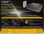
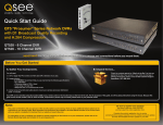
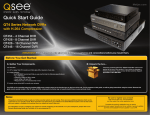
Quick Start Guide
QC Series Digital Network
Video Recorders (NVR)
For more information about your new
system, look for “QC” on our website or
in our online support materials at
www.q-see.com/support
IMPORTANT! This walkthrough will allow you to test your cameras and connections before you mount them.
Before You Get Started
A: Gather Your Components.
B: Unpack the box...
You will need:
Check the contents against the “What’s in the Box” list that was
packed at the top of your product. If you notice any damage or
missing components, please contact Q-See Customer Support at
www.Q-See.com/Support
1. An HDMI monitor, 19” or larger VGA PC monitor and VGA cable OR a television of any size.
2. A surge protector
We STRONGLY recommend that you use one that has the following specifications:
• UL-1449 Rated
• Clamping voltage of 330 or lower
• Joule rating of at least 400
• Response time of 10 nanoseconds or less
3. A power screw driver/drill to mount your cameras.
Your NVR can be controlled using the included USB mouse, remote control or the function keys on the front of the unit. For the purposes of this guide, we will be giving instructions using the mouse. Because this guide
covers several models in the QC series of NVRs, components in photos may not exactly match those on your particular model.
Be sure to register your product!
Visit www.Q-See.com,
click SUPPORT
and then select the online registration form.
Complete the product registration form to receive
warranty/technical support benefits and to be notified
of product updates and free downloadable firmware
updates to your NVR.
Note:
This poster is intended to help you get your Q-See security system up and running. There are many additional features which
can be customized to your specific needs. More information and instructions are available in the User Manual incuded on the
CD that came with your system or available for download from our website at www.Q-See.com.
For information on how to configure your system for remote monitoring on the Internet or on your smartphone, please refer to
the Remote Monitoring Guide also included on the accompanying CD.
Connect the Devices
STEP 1 Connect to a Monitor or Television
OPTION A:
Connecting a VGA PC Monitor
1. Plug the VGA cable into the port marked “VGA” on the back of the
NVR.
2. Plug the other end of the VGA cable into the similar port on the back
of the monitor.
3. Plug the monitor’s power cable into the surge protector.
STEP 2 Connect Mouse
Plug the mouse into the port labled “USB” on the rear of
the NVR.
NOTE: We recommend reserving the USB port on the
front of the NVR for use in backing up video files.
OPTION B:
Connecting a Television
OPTION C:
Connecting a HDMI Television (for NVRs equipped with an HDMI port)
1. Connect the BNC-to-RCA cable to the “Video Out” port on
the back of the NVR.
2. Plug the RCA end into the “Video In” port on the television.
3. Plug the television’s power cable into a surge protector.
If you do not see an image, check the Imput setting on the TV.
1. Plug an HDMI cable into the “HDMI” port on the back of the NVR.
2. Plug the other end into the “HDMI” port on the television.
3. Plug the television’s power cable into a surge protector.
STEP 3 Turning on the NVR
If you do not see an image, check the Imput setting on the TV.
3. Connect the power cables to the power adapters.
1. Connect the 12V power adapter to the NVR power port on the right
side of the NVR.
2. Connect the 48V power adapter to the power port on the left side
of the NVR next to the POE port.
4a. Plug the power cables into a surge protector
b. If your model has a power switch on the rear panel, use it to turn on
the NVR.
You will hear a beep as the NVR powers up.
The power supplies will be labelled and the power jacks will only
fit easily into the proper port.
1
2
3
4a
4b
Initial Set Up
IMPORTANT! You must follow these steps to enter the current date and time in order to effectively use the video search function described at the end of this guide.
Your NVR features a Startup Wizard that will guide you through the initial setup process including connecting your system to your network and the Internet. This Wizard should only be run during initial setup and should
be turned off once you’ve completed setup.
1. The Startup Wizard will launch once your NVR
has booted up. Choose the language you wish the
NVR to use from the pull-down menu.
If you change the language, the NVR will restart
allowing you to continue using the wizard in your
desired language.
You can click on the box next to Startup to
prevent the wizard from launching the next time
the NVR boots up. Click Next Step to continue.
2. Set the current date and time, along with your
preferred format for displaying dates (day, month
or year first). You should also select your time
zone along with whether it is Daylight Savings
Time and whether the NVR will use the 24-hour
method or the conventional AM/PM mode for
noting time. Enabling Time Server allows the NVR
to check a network server to maintain accurate
time.
3. The next window shows the recording status of all
the channels on both the main stream and the sub
stream which is used by computers and mobile
devices. You do not need to adjust these settings
at this time as your system is pre-configured to
record whenever a camera detects motion.
4. Click Next Step to to get to the Network Setup
explanation window.You should ensure that your
NVR is properly connected to your router using
an Ethernet or Network cable before continuing.
It is not recommended to connect the NVR to a
network hub, but rather directly to the router that
connects your system to the Internet.
In most cases, the router will have a light that
flashes when it detects a device properly
connected to that port.
When you are ready, click Next Step to allow
your system to connect to your network.
5. The NVR will attempt to connect to your
network’s router. If it is successful, it will display
your LAN (Local Area Network) address. This is
the address which you will use when accessing
the NVR from a computer or mobile device on
the same network (ie; within the same building
as the NVR).
If the attempt is unsuccessful, ensure that your
NVR is properly connected before clicking on
Prev. Step to try again.
Startup Wizard
STEP 4 Startup Wizard
Startup Wizard
Please choose your language.
Veuillez choisir votre langue.
Seleccione el idioma.
Escolha o idioma.
ENGLISH
Startup
1
Next Step
Cancel
GENERAL
System Time
2012 - 03 - 15
Date Format
YYYY MM DD
Time Server
10 : 06 : 12
Save
Set
Set
DST
Time Format
24-HOUR
2Default
Prev Step
Next Step
RECORD
Record Mode All
Schedule
Manual
Stop
Extra Stream
Record Mode All
Schedule
Manual
Stop
3
Prev Step
1 2 3 4
1 2 3 4
Cancel
6. Next, your NVR will attempt to establish
connectivity to the Internet through your router
using the UPnP protocol. Most routers have this
functionality.
NOTE: 2Wire brand routers do not offer UPnP
and you will need to consult the Networking
Guide poster to connect your NVR to the
Internet.
If you experience difficulties, please consult
your router’s manual to ensure that the UPnP
functionality is available and is enabled on your
router. Once you have adjusted your settings,
you may click on Prev. Step to go back and try
again.
You may get an error message if you attempt to
run the wizard a second time after a successful
connection.
7. If it is able to successfully communicate with the
router through UPnP, the NVR will access the
ports which you will use to control and view the
system over the Internet.
8. The NVR will also determine its Internet or
WAN (Wide Area Network) address. This is the
IP address which you will enter into a browser
window or remote monitoring program when
away from your network.
Checking Network Connection ....... SUCCESS
Getting IP address...... SUCCESS
DVR IP address is 192.168.0.102
To connect to this DVR from a computer or mobile device on the same local
network, enter the address shown below into an Internet Explorer browser
window or in the monitoring software. You should also write this address
down for later use:
http://192.168.0.102.85
5
Prev Step
Next Step
Checking Router for UPnP Function ....... SUCCESS
UPnP = Universal Plug and Play.
UPnP allows the DVR and your router to discover and communicate
with each other on your network so that you can access your DVR
from within or outside of the network through the router.
6
Prev Step
Next Step
Checking WAN IP address.......
Internet IP address is: 95.24.292.101
To connect to your DVR over the Internet or from outside of your local
network, input the address below into an Internet Explorer browser window
or in the remote monitoring software. You should also write this number
down for later use.
8
Prev Step
Next Step
Write down your network addresses:
9. When completed, you can close the wizard.
Local Address:___________________________________
Next Step
Cancel
Internet IP Address: _______________________________
Camera Set Up
IMPORTANT! If your bundle came with specialty cameras, such as a PTZ, please consult the instructions for that camera first.
STEP 5 Connecting the Cameras
2. Plug the other end of the Ethernet cable into any of
the Power over Ethernet (PoE) ports on the back of
the NVR.
1. Connect one of the long Ethernet cables to the
socket on the wire leading from the camera.
3. Repeat for additional cameras.
There will be a delay of a few seconds while the NVR communicates with the cameras
before their video stream appears. Cameras will appear on screen in the order that they are
connected, regardless of which port on the PoE block they are plugged into.
Cameras not directly connected to the NVR through the PoE ports will require their own power
supply (available separately). Please consult the User Manual or Remote Monitoring Guide for
cameras connecting to the NVR through a local network or through the Internet, respectively.
INSTALLING YOUR CAMERAS
1
2
When installing your cameras, it is important to select a proper site not only for field of view, but
for other considerations as well. The optimal location for your camera will depend on your unique
circumstances. As a general rule, the locations highlighted in green in the picture to the right indicate
the best locations to mount your cameras, but you should also take into consideration:
• Distance from NVR.
• Proximity to high voltage wires or other sources of electrical interference.
• Camera should be out of reach to avoid damage.
• Avoid direct exposure to weather.
• Do not place camera behind a window.
Operation
View 1
View 4
View 8
View 9
View 16
STEP 6 Login
Before you can access any of the NVR’s features,
you must first log in.
1. Right-click the mouse anywhere on the screen
to bring up the Shortcut Menu.
1. Open the Video Search window using the
Shortcut Menu as described in Step 6.
Pan/Tilt/Zoom
Color Setting
2. In the next step you will be searching for video,
so select Search at this time. This will bring up
the login screen.
Search
Record
Remote Device
Alarm Output
Main Menu
User Name: admin
Password: admin
SYSTEM LOGIN
3.To enter numbers or characters
click the appropriate field and a
virtual keyboard with appear.
User Name
admin
Password
!
4.Input the required password
and hit the ENTER key to
proceed.
STEP 7 Playback and Search
? @ # $ % ^ + * - _
q w e r t y u i o p |
a s d f g h j k l ; Enter
z x c v b n m , .
Shift
1 2
3
4 5
6
7 8
9
0
Refer to the User’s Guide if you wish to
change this password at a later time.
a
2. Your NVR is configured to record whenever motion is detected. Dates with recorded video will
be highlighted in blue.
3. To view these recordings:
a.Click on the desired date in the calendar
b.Blocks indicating the times of recorded videos
will be displayed in the Video Indicator and
Progress Bar at the bottom of the screen.
Videos will be color-coded based on their recording mode. Double clicking on a recording
block will start the playback.
c.You can adjust the playback position to anywhere in the clip or to another clip by clicking
with the cursor. You can adjust the scale of the
time bar for a more precise selection by clicking the Time Scale Button (c) to “zoom in”
down to the minute level.
0
1
Stop
b
REC
From R/W HDD
<
Su
1
8
15
22
29
Tu
3
10
17
24
31
00: 00: 00
2
3
4
Sync
5
6
7
All Record
8
Normal
9
10
Alarm
11
Motion
12
0
14
15
16
17
18
19
20
Jan
Mo
2
9
16
23
30
2012
We Th Fr
4 5 6
11 12 13
18 19 20
25 26 27
1
2
3
4
>
Sa
7
14
21
28
- 00: 00: 00
21
c
22
23
24
24hr