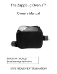
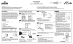
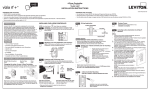
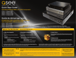
1
Installation Instructions
V.A.L.E.
TM
Two Brothers Racing
V a r i a b l e
A x i s
L o c k i n g
E x h a u s t
Juice Box™ - Fuel Controller
2006-08 Yamaha Raptor 700 Installation & Operation Manual
Part # 008-138
Thank you for purchasing a genuine Two Brothers Racing
JUICE BOX™. This product represents a radical step
forward in tuning fuel-injected motorcycles and ATVs for
optimal performance using “load-based” technology. We at Two Brothers Racing hope that you will find this
development as exciting and useful as we do. And
remember: Proper Fuel = Maximum Power!
7. Remove the stock fuel injector connector at the fuel
injector (Figure 5).
Fig 5
1. Make sure the vehicle is completely cool before starting
the installation. Also, make sure the vehicle is secure and
will not roll around.
2. Remove the seat.
3. Remove the radiator cover bolts. (Figure 1). Remove the
gas cap and gas tank cover. NOTE: replace the gas cap as
soon as the gas tank cover is removed.
Fig 1
8. Route the JUICE BOX™ wires under the gas tank frame
mount and up towards the fuel injector. (The aluminum
mount just above the battery (-) negative terminal on the
left side of the machine.)
9. Snap the female connector into the fuel injector. Snap
the original connector removed from the fuel injector
into the JUICE BOX™ male connector (Figure 6).
Fig 6
4. Remove the 2 bolts holding the side panels and 2 plastic
screws (Figure 2).
Fig 2
10. Remove the (-) battery terminal bolt and place ground
wire above the stock (-) terminal and re- install the (-)
terminal bolt (figure 7).
Fig 7
Parts Incuded
Qty.
Description
Part Number
1
3
1
Juice Box™ Fuel Control Kit
Zip Ties
Adhesive Velcro Square
008-138
Tools Needed For Install
5. Remove the 2 fuel tank mounting bolts and 2 plastic
screws that are holding the rubber flap (Figure 3).
Fig 3
- #2 Phillips Screwdriver
- 10mm Wrench
- 4mm Allen Wrench
11. For tuning purposes you may want to keep the JUICE
BOX™ where you can reach it. Once you get things
dialed in, route the JUICE BOX™ wire harness under the
battery mount and the two air box mounting tabs then
secure the harness to the frame with zip ties. The JUICE
BOX™ will easily fit in the rear toolbox area with the
supplied Velcro pad. (Figure 8)
IMPORTANT - PLEASE READ CAREFULLY
We recommend that this performance part be installed by a qualified ATV technician. If
you have any doubts as to your ability to install this performance part, please consult
with your local ATV dealer. Read all instructions first before starting installation. Make
sure the vehicle and exhaust system are completely cool before starting the installation.
Also, make sure the vehicle is secure during installation. Be sure to save all stock
components for possible use later.
6. Lift the tank up; you do not need to remove it (Figure 4)
and support with foam block from TBR exhaust packaging. Fig 8
Fig 41
The Juice Box™ is legal ONLY for closed course race vehicles. The Juice Box™ is not
applicable, nor inteded for use on EMISSIONS CONTROLLED street, highway or off-road
vehicles. The Juice Box™ is not applicable, nor inteded for use on aircraft.
Warranty
Two Brothers Racing warrants that this product carries a warranty for 2 years from date of purchase against original
defects in materials and workmanship. Should this product fail to perform for either of the above reasons, Two Brothers
Racing will repair or replace it with an equivalent product at no charge, except for postage, to the original retail purchaser.
To obtain the benefits of this warranty, the retail purchaser must return the product and proof of purchase to the place of
original purchase.
Operation Manual on page 2
Operation Manual
Two Brothers Racing
Juice Box™ - Fuel Controller
2006-08 Yamaha Raptor 700 Installation & Operation Manual
Part # 008-138
Installation Instructions continued...
12. Start the ATV. The green LED should now be scrolling
for about 3-5 seconds and then go to 1-2 steady green
LED’s or a single slow flashing green LED. If the number
1 green and number 8 red LED’s continue flashing after
startup, an injector wiring error is indicated. Re-check
the wires from the JUICE BOX™ and make sure they
are connected to the proper wire of your ATV’s stock
harness. MAKE SURE you have the correct connectors
selected in the stock harness. DO NOT PROCEED
UNLESS ABOVE CONDITIONS ARE MET. 13. Reassemble the ATV.
14. NOTE: Re check your wire routing and JUICE BOX™
location and make certain that in no way the wires can
come into contact with any moving parts or high heat
source and that the JUICE BOX™ is mounted in a way as
to not cause a handling problem with the machine.
Cleaning
If the unit requires cleaning, use a cloth that is only lightly dampened with water or mild detergent.
1. It is recommended that the pre-programmed settings of
the Juice Box™be used. However, the Juice Box™ can be
adjusted to suit different engine modifications, states of
tune and environmental conditions. To begin this process,
press the mode button. To enter each successive mode, just
press the mode button again. Note that every mode will
be identifiable by the color(s) of the flashing LED(s) on the
LED display. There are six modes that are distinguished
by an LED color or color combination. The 6 modes are
as follows, respectively: Green, Yellow, Red, Green-Blue,
Yellow-Blue and Red-Blue.
2. You are now ready to manually program each mode. Consult the base settings supplied with the unit.
To program the Juice Box™, the bike must be running in
order to supply power to the Juice Box™. Simply press the mode button to activate the first mode. If at anytime you stay in an adjustment mode for longer
than 5 seconds without pressing any buttons, the Juice
Box™ will exit the adjustment mode and will return to the
operational mode.
To save settings in a particular mode press the MODE
button which goes to the next adjustable mode or wait for
the Juice Box™ to exit back to the operational mode. The settings in each mode are adjusted by pressing the
(+) and (-) buttons located on the right and left side of the
mode button, respectively. For easy reference, the LEDs are
numbered 1 through 8. However, the LEDs can be adjusted
to the following positions: 0.5, 1, 1.5, 2, 2.5, 3, 3.5, 4, 4.5, 5,
5.5, 6, 6.5, 7, 7.5, 8. For example, in a particular mode, if LED
4 is flashing then the LED display is set to 4 in that mode. If
the (+) button is pressed once then LEDs 4 and 5 will flash
simultaneously and the LED display is set to 4.5. If the (+)
button is pressed once again, only LED 5 will flash and the
LED display is set to 5. The LED display can also be set
to 0.5 by pressing the (-) button and scrolling the colored
LED to position 1 and then pressing the (-) button once
more until the LED in position 1 is flashing twice as fast as
normal. I. The first mode (Green Mode) represents an
additional amount of fuel added under cruise conditions. A flashing green LED should appear on the LED display. To add more fuel, scroll the flashing green LED to the right
using the (+) button. To add less fuel, scroll the flashing
green LED to the left using the (-) button. If you set the
flashing green LED to the 0.5 position on the LED display,
no fuel will be added to the stock fuel curve.
II. The second mode (Yellow Mode) represents an
additional amount of fuel added during acceleration. A
flashing yellow LED should appear on the LED display. To
add more fuel, scroll the flashing yellow LED to the right
using the (+) button. To add less fuel, scroll the flashing
yellow LED to the left using the (-) button. If you set the
flashing yellow LED to the 0.5 position on the LED display,
no fuel will be added to the stock fuel curve.
III. The third mode (Red Mode) represents an additional
amount of fuel added during full throttle conditions. A
flashing red LED should appear on the LED display. To add
more fuel, scroll the flashing red LED to the right using the
(+) button. To add less fuel, scroll the flashing red LED to
the left using the (-) button. If you set the flashing red LED
to the 0.5 position on the LED display, no fuel will be added
to the stock fuel curve.
Note: If the flashing green, yellow and red LEDs in modes
1 through 3 (Green, Yellow and Red) are set to the 0.5
position on the LED display then the Juice Box™ will not
add any fuel to the bike’s stock fuel curve. This setting will
essentially turn off the Juice Box™ even though it is still
attached to the bike’s fuel injection system. The bike will
run as though the Juice Box™ is not installed. The Juice
Box™ LEDs will still operate normally even though no fuel
is being added.
IV. The fourth mode (Green-Blue Mode) is not required
for this particular model.
V. The fifth mode (Yellow-Blue Mode) is an adjustment
to determine the time when the acceleration/Yellow Mode
fuel amount turns on. A flashing yellow LED appears on
the LED display while at the same time a flashing blue LED
appears on the 8th LED. To increase the sensitivity and
therefore cause the Yellow Mode fuel to turn on sooner,
scroll the flashing yellow LED to the left using the (-) button. To decrease the sensitivity and therefore cause the Yellow
Mode fuel to turn on later, scroll the flashing yellow LED to
the right using the (+) button.
VI. The sixth mode (Red-Blue Mode) is an adjustment
to determine the time when the full throttle/Red Mode fuel
amount turns on. A flashing red LED appears on the LED
display while at the same time a flashing blue LED appears
on the 8th LED. To increase the sensitivity and therefore
cause the Red Mode fuel to turn on sooner, scroll the
flashing red LED to the left using the (-) button. To decrease
the sensitivity and therefore cause the Red Mode fuel to
turn on later, scroll the flashing red LED to the right using
the (+) button.
Operation Manual - JUICE BOX™ Settings
Pre-set Settings: Raptor 700 with stock airbox, TBR Slip-on exhaust with spark arrestor. (G=3 Y=3.5, R=2, GB=N/A, YB=3, RB=3)
(Same settings for Raptor 700 with airbox lid off, TBR Slip-on exhaust with NO spark arrestor and P1 Power Tip installed.)
Mode 1 - Green
Mode 2 - Yellow
Mode 3 - Red
Mode 4 - Green/Blue
Mode 5 - Yellow/Blue
Mode 6 - Red/Blue
Two Brothers Racing
Juice Box™ - Fuel Controller
2006-08 Yamaha Raptor 700 Installation & Operation Manual
Part # 008-138
Additional Tested Setting: Raptor 700 with airbox lid off and TBR Slip-on exhaust with spark arrestor.
(G=3, Y=4, R=2.5, GB=N/A, YB=3, RB=3)
Mode 1 - Green
Mode 2 - Yellow
Mode 3 - Red
Mode 4 - Green/Blue
Mode 5 - Yellow/Blue
Mode 6 - Red/Blue
For Race Use Only
The Juice Box™ is legal ONLY for closed course race vehicles. The Juice Box™ is not
applicable, nor inteded for use on EMISSIONS CONTROLLED street, highway or off-road
vehicles. The Juice Box™ is not applicable, nor inteded for use on aircraft.
For additional settings please visit our website at www.twobros.com.