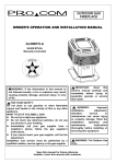
1
CAMPFIRE
OWNER’S OPERATION AND INSTALLATION MANUAL
PL600HYLA/PL600HYLB
60,000BTU/Hr
PN750HYLA/PN750HYLB
75,000BTU/Hr
Manually Controlled
WARNING: If the information in this manual is
not followed exactly, a fire or explosion may
result causing property damage, personal injury,
or loss of life.
FOR YOUR SAFETY:
Do not store or use gasoline or other flammable
vapors and liquids in the vicinity of this or any
other appliance.
IMPORTANT: Read this owner’s manual
carefully and completely before trying to
assemble, operate, or service this heater.
WHAT TO DO IF YOU SMELL GAS:
-Shut off supply to the appliance.
WARNING: Improper installation, adjustment,
alteration, service, or maintenance can cause
-Extenguish any open flames.
-Immediately call your gas supplier. Follow
injury or property damage. Read the installation,
operating and maintenance instructions
the gas supplier’s instructions.
-If you can not reach your gas supplier, call
thoroughly before installing or servicing this
equipment
the fire department.
Installation and service must be performed by
a qualified installer, service agency or the gas
supplier.
WARNING: For Outdoor Use Only. Do not
use for cooking
Save this manual for future reference.
Installer: Leave this manual with customer.
1
GENERAL INFORMATION
These instructions are intended as a general guide and do not supersede national or local codes in anyway.
Authorities having jurisdiction should be consulted before installation.
Installation and provision for combustion and ventilation air must confirm with the national Fuel Gas Code. This
campfire has been tested to, and complies with IAS 4-96 1997, U, S, Requirements for Outdoor Gas Fireplace
TABLE OF CONTENTS
GENERAL INFORMATION……………………………………………………………….........2
SAFETY INFORMATION………………………………………………………………...........3
INSTALLATION .……………………………………………………………………..……....... 5
OPERATING HEATER ………………………………………………..…………………........7
MAINTENANCE AND STORAGE ……………………………………………………..........8
PRODUCT FEATURES……………………………………………………………………......9
SPECIFICATION…………………………………………………………….........…………...10
TROUBLESHOOTING……………………………………………………………………... ..10
PARTS LIST…………………………………………………………… …………………….....11
WARRANTY………………………………………………………………………………….....end
Liquid propane units are designed and certified for use only with household liquid propane supply period. Do not use “portable” propane tanks of
less than 100-lbs, Capacity, LP units cannot be operated with 20-lb. Propane
tanks commonly used with portable, liquid propane gas grills.
2
SAFETY INFORMATION
PROPER CLEARANCES FROM COMBUSTIBLE, CONTHIS GAS APPLIANCE IS DESIGNED FOR OUTDOOR USE ONLY.
IT IS NOT INTENDED FOR INSTALLATION IN ANY BUIDING,
GARAGE.OR ENCLOSED STRUCTION. IT IS NOT INTENDED FOR
INSTALLATION IN OR ON RECREATIONAL VEHICLES OR BOATS.
WARNING: Follow all gas leak procedures in
this manual, prior to operation.
STRUCTION AND MATERIALS MUST BE MAINTAINED
FROM ALL SIDES, TOP AND BOTTOM OF THIS
APPLIANCE.
THIS APPLIANCE SHOULD NEVER BE PLACED ON
ANY COMBUSTIBLE SURFACE.
THIS APPLIANCE SHOULD NEVER BE PLACED UNDER
ANY COMBUSTIBLE CONSTRUCTION OR MATERIALS.
THIS APPLIANCE SHOULD NEVER BE PLACED
WARNING: Fuels used in gas fired appliances,
and the products of combustion of such fuels,
contain chemicals know to the State of California
to cause cancer, birth defects and /or other
reproductive harm. This warning is issued pursuant
to California Health & Safety Code Sec.25249.1
CLOSER THAN FORTY-EIGHT (48”) INCHES FROM
ANY SIDE TO ANY COMBUSTIBLE CONSTRUCTION
OR MATERIALS.
Location
Your campfire can be installed on a flat, stable surface,
While this appliance is not in use, the gas must be
turned off at the gas supply.
away from any combustible materials or construction.
(See FIgure 13)
While this appliance is not in use, it should be covered
Place unit on any level, outdoor, non combustible
surface.
to protect it from weather and other adverse elements.
DO NOT ATTEMPT TO DISCONNECT THE GAS OR ANY
GAS FITTING WHILE THIS APPLIANCE IS IN OPERATION.
Inspect the gas connections of this appliance prior to
each use. Do not operate the unit if there is a gas leak
NOTE: Do not place this appliance on grass or dirt
area , this may prevent proper venting.
HARD PIPING TO UNIT WITHOUT GAS PROXIMITY
1. TURN OFF THE GAS SUPPLY SYSTEM
NOTE: All gas connections (except for brass to
brass) require the following:
present.
Do not put anything flammable, on or around or be-
Clean pipe threads using either a wire brush or steel
wool. Apply Teflon tape or pipe dope to the steel
neath the campfire.
NEVER Leave the campfire unattended while in
operation.
NEVER Allow children to operate this appliance.
NEVER Lean over the campfire or place ,hand or fingers on the screen cover or near flame.
fittings before making any connection.
BE CAREFUL! Make sure all gas connections are
snug, but not over tighten!
2. Extend the gas supply system using1/2” black iron
pipe from current house supply. This may be accomplished by a teeing off” or tapping into a con-
NEVER Use liquid propane gas in a natural gas unit,
or natural gas in a liquid propane unit. Gas conver-
venient gas line connection; installing the necessary pipe for the distance required; and then in-
sions SHOULD ONLY BE DONE BY A QUALIFIED
SERVICE TECHNICIAN. DO NOT use charcoal bri-
stalling a manual valve at exterior house wall. If
pipe is to pass though a foundation or house wall,
quettes or lighter fluid in any campfire.
Storage of this appliance indoors is permissible only if
the gas is disconnected.
make sure to re-seal the area around the pipe with
weather sealant.
3. From manual valve, extend piping to the campfire.
3
Location Continue
Storage of this appliance indoors is permissible only
Note :If pipe is to be placed in an underground trench,
check with local codes for required depth and mate-
if it has been disconnected from its fuel supply. (natural
gas line or LP gas)
rial construction.
4. Connect the 3/8” male flare brass fitting (furnished
with campfire) to the 1/2” steel piping making sure
to clean the pipe threads and use Teflon tape or pipe
dope.(FLEX LINE NOT SUPPLIED)
5. Connect the 1/2” female X 3/8” male flare brass
fitting to the 3/8” female brass flare fitting, as
sembled on the right side of the gas line, of the
right side of the campfire.
NOTE: Brass to brassw connections do not require
teflon tape or pipe dope.
(Note: show drawing of hard piping installation.
LOCAL CODES
Install and use heater with care. Follow all local codes.
In the absence of local codes, use the latest edition of
The National Fuel Gas Code, ANSZ223.1, also known
as NFPA54*.
Available from :
American National Standards Institute, INC.
1430 Broadway, New York, NY10018
National Fire Protection Association, INC.
Battery march Park Quincy. MA 02269
Do not use this appliance if any part has been under
water. Immediately call a qualified service technician
to inspect the appliance and to replace any part of
control system and any gas control which has been
under water.
Children and adults should be alerted to the hazards
of high surface temperatures and should stay away
IMPORTANT: Installation of natural gas and LP
should be done by a qualified installer, service
to avoid burns or clothing ignition.
Young children should be carefully supervised when
agency or gas supplier.
they are in the area of the appliance.
Never leave the appliance unattended during
The appliance and its manual shutoff valve must
be disconnected from the gas supply piping sys-
operation.
Clothing or other flammable materials should not
tem during any pressure testing of the system
at test pressures in excess of 1/2 psig (3.5kPa).
be placed on or near the appliance.
∙ Any guard or other protective device removed for
This appliance must be isolated from the gas
servicing the appliance must be replaced prior to
operating the appliance
supply piping system by closing its manual
shutoff valve during any pressure testing of the
∙ Installation and repair should be done by a qualified service person.. The appliance should be in-
gas supply piping system at test pressures equal
to or less than 1/2 psig (3.5kPa).
spected before use and at least annually by a qualified service person. More frequent cleaning may
be required as necessary. It is imperative the control compartment, burners and circulating air passageways of the appliance be kept clean.
∙ Inspect the fuel supply connection before each use
of the appliance.
4
Installation
LOGS LIST
PL600HYLA PN750HYLA
FIG 2 The LOG sets for PL600HYLA/ PN750HYLA
PL600HYLB PN750HYLB
FIG 3 The LOG sets for PL600HYLB/ PN750HYLB
5
Installation continue
Check to make sure you have the correct parts before 7. Install the No.#1 log as indicated on base log .Fix
assembling.
the log on the bracket by the screw .
. Logs: 5
(FIG.-6).
C aution: Some of the steel edges may be
sharp. Please use caution when assembling
the unit.
INSTALLATION INSTRUCTIONS:
1. Remove log from inside the box. Please note each log fits
the number marked on foam package.
2. Next remove campfire from box.
3. You may use bricks or blocks to create your sur-
Fig. 6 Install the LOG #1
round to place your campfire on.
4. Make sure that the campfire is placed on a flat
surface.
5. Check the log piece (FIG-4).
8.
Install the No.#2 log as indicated on base log.
(FIG.-7).
Fig.-4 Check the log piece
6. Make sure that the logs were installed correctly.
(FIG.-5).(Base logs are pre-installed.)
Fig. -7 install the LOG #2
9.
Install the No.#3 log as indicated on the base log
( FIG.-8).
Fig. -8 install the LOG #3
Fig.-5 Install and check the base logs
6
Installation (continue)
FUEL REQUIREMENTS:
Natural gas models
11. install the No. # 4 log as indicated on the base
(FIG.-9).
l
- Connect the ON/OFF gas valve of the appliance
to the incoming gas supply line. See Figure 10. - Make certain all gas connections are right.
- Turn the ON/OFF valve at the appliance slowly
to the “ON” position. Use a soap and water
solution to test for leaks.
Fig. -9 Install the LOG #4
12. Install the No. #5 Log as indicated on the base log
(FIG. 10).
Fig. 11 Natural gas burner assembly
FIG. -10 Insatll the LOG #5
OPERATING HEATER
Your campfire burener is build to operate with natural
gas or build for LP gas.
CONNECTING TO GAS SUPPLY
Note: Apply a mixture of liquid soap and water to all
joints. Do not use an open flame. Bubbles forming
show a leak. Check all connections for leaks
immediately.
This appliance is lit a piezo ignitor, follow these instructions exactly when lighting the campfire. BEFORE
LIGHTING, smell arround the appliance the appliance
area for gas. Be sure to smell to next to the ground as
liquid propane gas heavier than air and will settle to the
ground.
Follow adaptable lighting instructions. Apply soap solution to all joints. Bubbles forming indicates a leak. Do
not use a match or an open flame to detect leak. Light
heater after ensuring that no gas leak exists.
7
LIGHTING INSTRUCTIONS
TO TURN OFF GAS TO APPLIANCE
Shutting Off Appliance
WARNING:FOR YOUR SAFETY READ
BEFOR LIGHTING
1. STOP! Read the safety information above.
2. Make sure manual shutoff valve is fully open.
3. Press in and turn control knob clockwise
90
1. Turn control knob clockwise
the PILOT position.
90 degrees to
2. Press in and turn control knob
degrees to OFF position.
clockwise 90
Shutting Off Burner Only (pilot stays lit)
Turn control knob clockwise
90 degrees to the
degree to the OFF position.
4. Wait five (5) minutes to clear out any gas. Then
PILOT position.
smell for gas around log set and near floor. If you
smell gas, STOP! Follow the safety information
above. If you don’t smell gas, go on to the next step.
5. Turn control knob counterclockwise
90
degree to the PILOT position and press in. Keep control knob pressed in for five(5) seconds.
Note: You may be running this log set for first time
after hooking up to gas supply. If so, the control
knob may need to be pressed in for 30 seconds.
This will allow air to bleed from the gas system.
Fig12 The operationg board
6. With control knob pressed in, push down and release ignitor button. This will light the pilot. The pilot is attached to the side of the front burner. If
needed, keep pressing ignitor button until pilot
MAINTENANCE AND STORAGE
lights.
NOTE: If pilot does not stay lit, contact a qualified
1. Storage of an appliance indoors is permissible
only if the gas supply system is disconnected and
removed from the appliance. .
service person or PRO-COM’s 800# on the back
of this manual. Until repairs are made, light pilot
2. Have the heater inspected by qualified service
man before each use or at least annually.
with the piezo.
7. Keep control knob pressed in for 30 seconds after
3. Check the POL fitting for any damage before each
use and replace if any damage is found.
lighting pilot. After 30 seconds, release control knob.
Note: If pilot goes out, repeat steps 3 through 7.
4. Spiders and insects can nest and live in outdoor
appliances, especially in the burners and orifices.
If control knob does not pop up when released, contact a qualified service person or PRO-COM’s 800#
on the back of this manual.
8. Turn control knob counterclockwise
This will interrupt the normal flow of LP gas to
the heater and can be a very dangerous situation.
90
Inspect for insect infiltration of burner/orifice when
one of the following occurs:
degree to the ON position. Burner should light. If
burner does not light, call a qualified service person
A. The smell of gas along with predominating yellow tipping of the burner flames.
or PRO-COM’s 800# on the back of this manual.
B. Heater can not reach desired temperature.
C. Uneven burner flow.
WARNING: If you do not follow these instructions exactly, a fire or explosion may
result causing property damage, personal in-
D. Burner makes popping noises during normal
use or shutdown.
jury or loss of life.
5. Adopt rainproof cover (provided with the heater)
to avoid rust of heater when not in use.
8
PRODUCT FEATURES
SERVICE INDICATIONS:
SAFETY PILOT
A hazardous condition may result if a heater has been
The heater has a pilot with a safety shutoff system.
modified or is not functioning properly. When the
heater is working properly:
The safety pilot is a required feature for outdoor
heaters. It shuts off the heater if flame is extinguished
1. The flame is essentially yellow.
by rough wind.
2. There is no strong disagreeable odor, eye burning or other physical discomfort.
PIEZO IGNITION SYSTEM
3. No smoke or soot exists internal or external to the
This heater has a piezo igniter. This system requires
campfire.
no matches, batteries, or other sources to light heater.
4. No unplanned or unexplained shut down of the
VALVE CONTROL SYSTEM
This heater has a control valve to control the gas flow,
heater occur.
with the control valve, you can chose the proper flame
of the fire.
REPLACEMENT
REPLACEMENT PARTS:
*Option Screen*
Note: Use only original replacement parts. This will
protect your warranty coverage for parts replaced under warranty.
For Your safety
You may purchase the screen to maintain a clearance
around the campfire
PARTS UNDER WARRANTY:
Contact authorized dealers of this product. If they can’t
CAUTION
supply original replacement part(s) call PRO-COM’s
Technical Service Department at 1-877-886-5989 for
PLEASE DO NOT TOUCH SCREEN OR PLACE ANY
OBJECTS ON SCREEN WHILE BURNER IS ON
referral information.
Children and adults should be alerted to the hazards
When calling PRO-COM or your dealer, have ready
of high surface temperatures and should stay away
Your name
Your address
Model and serial numbers of your heater
How heater was malfunctioning
Type of gas used (propane/LP or natural gas)
Warranty card
Usually, we will ask you to return the defective
part back to retail store.
from SCREEN to avoid burns or clothing ignition,
PARTS NOT UNDER WARRANTY:
Contact authorized dealers of this product or Parts
Central if they can’t supply original replacement part
(s) Call PRO-COM’s Parts Department at 1-877-8865989 for referral information.
When calling PRO-COM, have ready
FIG. 13 The screen
9
Model number of your heater
The replacement part number
ACCESSORIES
HIGH ALTITUDE DERATE
Purchase the accessories from your local dealer or
In the U.S.A., Input BTU shall be derated 4%(1 orifice
Parts Central. If they cannot supply these accessories
size) per 1000ft, for above 2000ft.. In Canada, input BTU
call PRO-COM’s Sales Department at 1-877-886-5989
shall be derated 10% (2 orifice size) at altitudes from
for referral information. You can also write to the ad2000ft.to 4500ft..
dress listed on the back page of this manual.
SPECIFICATIONS
Model
L600HYLA/B
PN750HYLA/B
Btu (LP/NG)
60.000
75.000
Gas Type
LP
NG
Ignition
Piezo
Piezo
Inlet Gas Pressure* (In. of water)
Maximum
14”
10.5”
Minimum
11”
5.5”
Dimensions, Inches (H x W x D)
Stove
17 3/4” x22 7/8”x18 1/8”
17 3/4” x22 7/8”x18 1/8”
Carton
15” x25 ”x20 1/4”
15” x25 ”x20 1/4”
Weight, Lbs
Stove
32/33
32/ 33
Shipping Weight
55/58
55/ 58
* For purpose of shipment adjustment.
Minimum clearances: Bottom:
(This appliance may not be place on any combustible materials)
Top:
8 FT. (2.4m)
Side /walls (around): 48 inch (1220mm)
TROUBLESHOOTING
OBSERVED PROBLEM
POSSIBLE CAUSE
Burner does not light
1.
Air in gas lines.
2.
Inlet gas pressure is too low.
2.
removed.
Check gas pressure.
3.
4.
Gas supply turned off.
Air passageway on heater blocked.
3.
4.
Fully open gas supply.
Check air passageway.
5.
6.
Burner orifice clogged.
Control knob not in ING/ON position.
5.
6.
Clean burner.
Turn control knob to ING/ON position.
7.
Control knob not fully pressed in while
in ING/ON position.
7.
Press down control knob.
1.
Ignitor electrode positioned wrong.
1.
Reposition ignitor.
2.
3.
Ignitor broken.
Broken ignitor cable.
2.
3.
Replace pilot
Replace ignitor cable.
4.
Ignitor electrode not connected to ignitor cable.
4.
Connect electrode to ignitor cable.
1.
Damaged thermocouple.
1.Replace thermocouple.
2.
3.
Thermocouple electrode corrosion.
Damaged control valve.
2.
3.
Clean thermocouple electrode.
Replace control valve.
4.
Control knob not pressed long enough.
4.
After pilot lights, keep control knob
pressed in for 30 seconds.
5.
Thermocouple connection loose at control valve.
5.
Hand tighten connection or replace
thermocouple.
6.
Pilot flame not touching thermocouple.
6.
Contact qualified service man.
When ignitor buttons
pressed in, there is no
spark at safety Pilot.
Burner fire does not last.
REMEDY
1.
10
Continue holding down control knob.
Repeat igniting operation until air is
PARTS LIST
PL600HYLA/PL600HYLB
PN750HYLA/PN750HYLB
11
ILLUSTRATED
PARTS BREAKDOWN
PL600HYLA / PL600HYLB
PN750HYLA / PN750HYLB
12
WARRANTY INFOR ATION
KEEP THIS WARRANTY
Model:
Serial No.
Date Purchased
Always specify model and serial numbers when communicating with PRO-COM.
We reserve the right to amend these specifications at any time without notice. The only warranty applicable is our standard written warranty. We
make no other warranty, expressed or implied.
LIMITED WARRANTY PRO-COM OUTDOOR CAMPFIRE
PRO-COM warrants this product to be free from defects in materials and components for one (1) years from the date of first purchase, provided
that the product has been properly installed, operated and maintained in accordance with all applicable instructions, to make a claim under this
warranty, the Bill of Sale or cancelled check must be presented.
This warranty is extended only to the original retail purchaser. This warranty covers the cost of part(s) required to restore this heater to proper
operating condition and an allowance for labor when provided by a PRO-COM Authorized Service Center. Warranty part(s) MUST be obtained
through authorized dealers of this product and/or PRO-COM who will provide original factory replacement parts. Failure to use original factory
replacement parts voids this warranty. The heater MUST be installed by a qualified installer in accordance with all local codes and instructions
furnished with the unit.
This warranty does not apply to parts that are not in original condition because of normal wear and tear or parts that fail or become damaged as
a result of misuse, accidents, lack of proper maintenance or defects caused by improper installation. Travel, diagnostic cost, labor, transportation and any and all such other costs related to repairing a defective heater will be the responsibility of the owner.
TO THE FULL EXTENTALLOWED BY THE LAW OF THE JURISDICTION THAT GOVERNS THE SALE OF THE PRODUCT, THIS EXPRESS WARRANTY EXCLUDES ANYAND ALL OTHER EXPRESSED WARRANTIES AND LIMITS THE DURATION OF ANYAND ALL IMPLIED WARRANTIES
INCLUDINGWARRANTIESOFMERCHANTABILITYANDFITNESSFORAPARTICULARPURPOSETOONE(1)YEARONALLCOMPONENTSFROM
THE DATE OF FIRST PURCHASE. NANJING PRO-COM’S LIABILITY IS HEREBY LIMITED TO THE PURCHASE PRICE OF THE PRODUCT AND
NANJINGPRO-COMSHALLNOTBELIABLEFORANYOTHERDAMAGESWHATSOEVERINCLUDINGINDIRECT.ACCIDENTALORCONSEQUENTIAL DAMAGES.
Some states do not allow a limitation on how long an implied warranty lasts or an exclusion or limitation of accidental or consequential damages,
the above limitation on implied warranties, or exclusion or limitation on damages may not apply to you.
This warranty gives you specific legal right, and you may also have other rights that vary from state to state.
For information about this warranty please write to:
NANJING PRO-COM ELECTRIC APPLIANCE CO., LTD.
#6 CHUANGYE ROAD, HIGH NEW TECHNOLOGY & DEVELOPMENT ZONE,
GREAT BRIDGE ROAD NORTH, NANJING, 210061, CHINA.
Patent Pending
PRO-COM TOLL- FREE NUMBER: 1- 877- 886- 5989
13